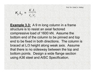
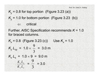
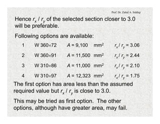
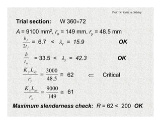
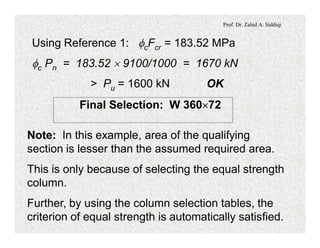
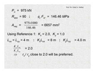
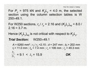
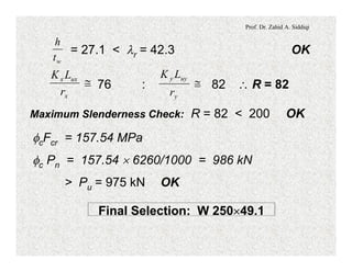
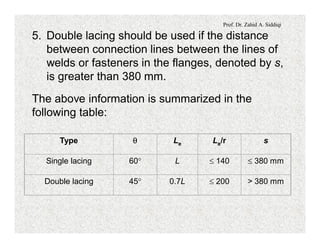
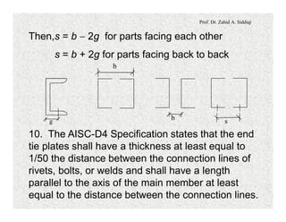
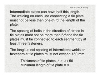
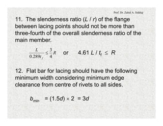
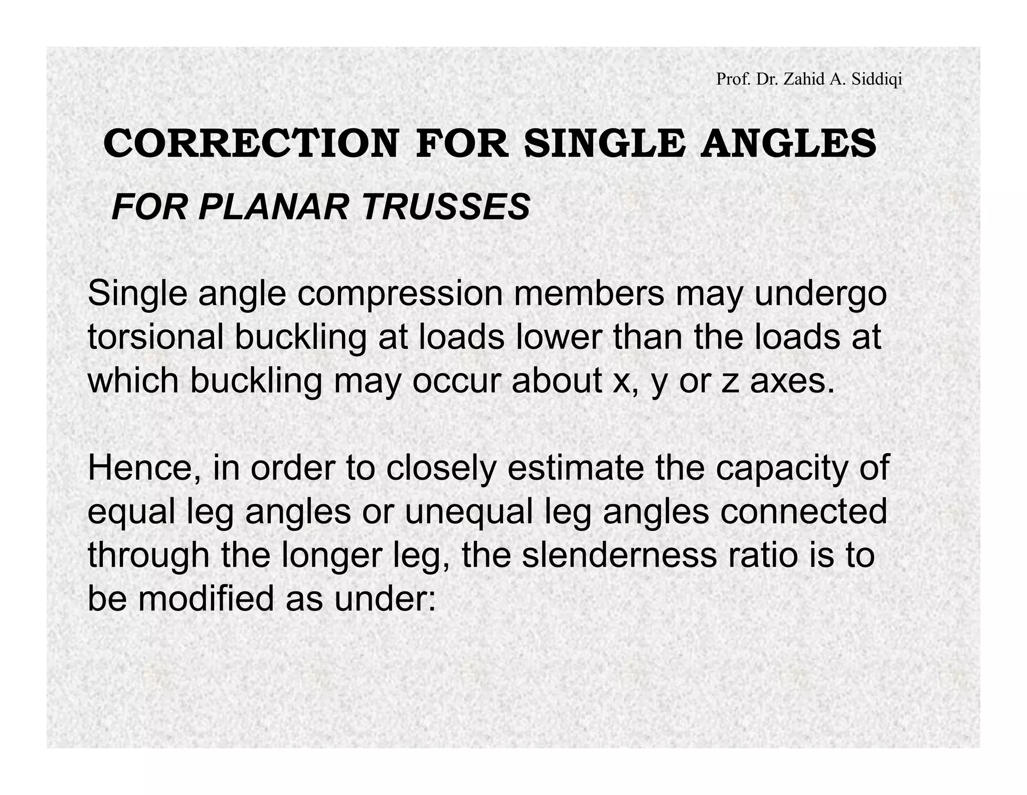
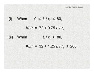
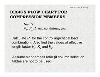
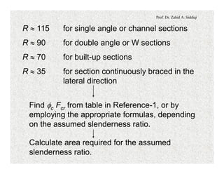
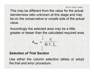
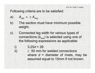
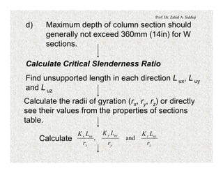
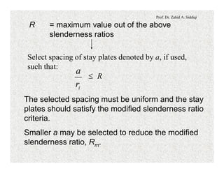
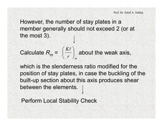
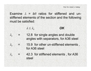
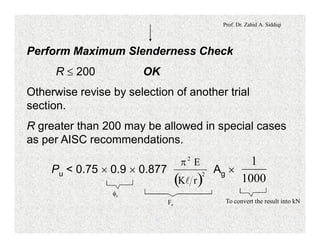
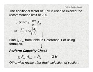
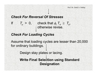
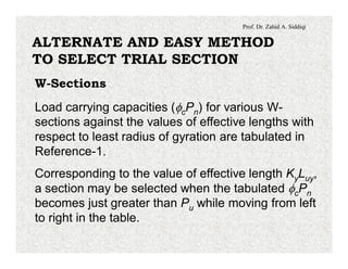
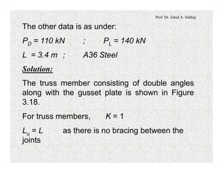
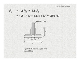
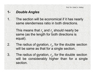
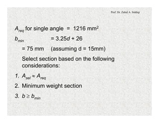
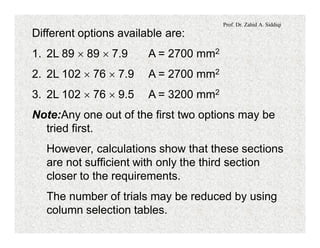
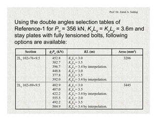
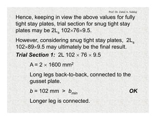
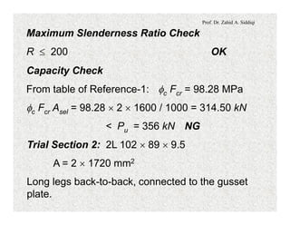
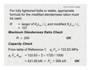
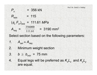
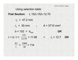
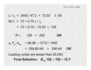
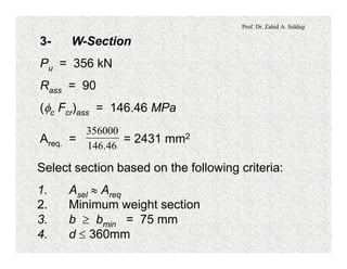
The document discusses the design of compression members in planar trusses. It provides modifications to the slenderness ratio that must be applied when designing single angle compression members to account for potential torsional buckling. It then outlines a design flow chart for selecting compression member sections, including calculating required member capacity and area, selecting a trial section, and performing various checks related to stability, slenderness ratio and member capacity. An alternate method for selecting W-sections or double angle sections using column selection tables is also described.
![Prof. Dr. Zahid A. Siddiqi
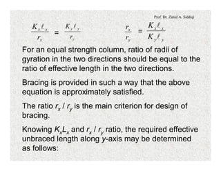
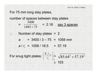
Exact calculations for ry (to be made only for the
last trial):
Iy = 2 ´ [123 ´ 104 + 1720 ´ (24.3 + 5)2]
= 541.3 ´ 104 mm4
(ry)exact = = 39.7 mm
17202
103.541 4
´
´
= @ 107
x
uxx
r
LK
8.31
34001´
= @ 85.64
y
uyy
r
LK
7.39
34001´](https://image.slidesharecdn.com/steelstrucurelec7-200810021452/85/Steel-strucure-lec-7-33-320.jpg)
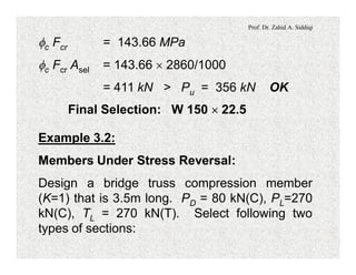
![Prof. Dr. Zahid A. Siddiqi
Using the W-shape selection tables of Reference-1
for Pu = 356 kN, KyLy = 3.4m, following option is
obtained [(KyLy)eq is not critical]:
Trial Section: W150 ´ 22.5
rx = 65 ; ry = 37.1 ; A = 2860 mm2
bf / 2 = 152 / 2 = 76 mm > bmin OK
l = = 11.5 < lr = 15.9 OK
f
f
t
b
2
l = = 21.6 < lr = 42.3 OK
wt
h
R = = @ 92 < 200 OK
.minr
Kl
1.37
3400](https://image.slidesharecdn.com/steelstrucurelec7-200810021452/85/Steel-strucure-lec-7-42-320.jpg)