Downloaded 782 times


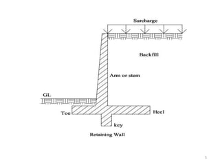
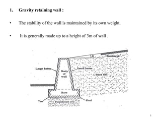

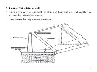
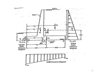

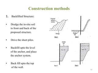
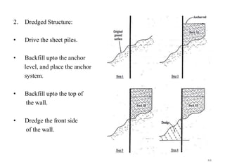
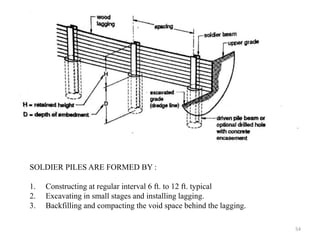


This document provides an overview of different types of retaining walls, including gravity, cantilever, counterfort, sheet pile, and diaphragm walls. It discusses the key components and design considerations for gravity and cantilever retaining walls. Gravity walls rely on their own weight for stability, while cantilever walls consist of a vertical stem with a heel and toe slab acting as a cantilever beam. The document also covers lateral earth pressures, drainage of retaining walls, uses of sheet pile walls, and construction methods for diaphragm walls.