SlideShare a Scribd company logo
1 of 4
Main InductionMotor Characteristics ;

                                  jXth         jX2
                    Rth
                                                        i2

              +
                                                             R2/s
        Vth


              -


                     jXm
Vth                           V 1 , Zth              ( R1    jX 1) / / jXm …….. (1)
         R1       j ( X 1 Xm)

                         Vth
I2                                            …….. (2)
                  R2
        ( Rth        )      j ( Xth X 2)
                  s

                          Vth 2
I 22                                            …….. (3)
                   R2 2
         ( Rth       ) ( Xth X 2) 2
                   s

                     3Vth 2                     R2 1
                                                       …….. (4)
                  R2 2
       ( Rth        ) ( Xth              X 2) 2 s 2 fs
                  s

Note :Torque – slip curve is depending on 3 of thevariables; Stator Voltage, Stator frequencyand
Rotor Resistance.

Toget an idea aboutthetorquecurvewemayfindthe slip valueforwhichtorque is maximum.
Actuallytofindmaximumtorque, thetorqueequation can be derivedwithrespectto slip(s)
andthederivation is equatedtozeroandcorresponding slip valuewill be themaximumtorque slip.
However, it is toocomplicated. Anotherwaytofindthemaximum slip is Rule of Maximum Power
Transfer, maximumtorque is satisfiedwhenthemaximumpower is transferedto R2/s resistance.
Togetmaximumpowerto R2/s ;

          R2
                abs( Rth       j ( Xth X 2)) …….. (5)
          s

Withthisequation;

                     R2
st max                             …….. (6)
           Rth 2 ( Xth X 2) 2

                          3Vth 2
 max                                             …….. (7)
         2 s ( Rth        Rth 2 ( Xth X 2) 2 )

Note :Theequations 6 and 7 showsthatmaximumtorque is not depending on rotor resistanceandthe
slip value at torquemaximumincreaseswithincreasing rotor resistance. Thusthetorque –
speedcurveswhen an externalresistanceaddedtothe rotor terminalsare as below.
Characteristics of Scherbius Machine;

Scherbius Machine is actually a polyphasecommutatormachinewith 3 phase stator
excitingwindingsand a commutator set in armature.The rotor is woundedsinglephase but
designedtogive 3 phasevoltage;therefore, threesets ofcommutatorcarbonbrushesplaced 120 degrees
apart electricallytofor 3 phaseoperation.


The stator excitorwinding is energizedwiththe rotor current of the main inductionmachine.
Theexcitorinducedemfmagnitude can be calculatedwiththefollowingwellknownformula;

e 4.44 *      *   Ns * f …….. (8)

Note :Theactualsignal is a sine wavewithfrequency f, thisformulagivesthemagnitude.

Similarlyinducedemf in rotor commutatorswill be

                              p
E 4.44 *       *   Nr * n *     …….. (9)
                              2

where

         Ns is effectivenumber of turns in stator windings

         Nr is effectivenumber of turns in rotor windings

             isfluxperpole

         f is thefrequency of stator excitingvoltage


Note : Pleaseseethetopologyfor rotor and stator connections. Rotor and                   stator
terminalsareconnectedeachothervia an autotransformerwithchangingturnsratio say Kt.

Thus;

E
        KT
e
      Nr n    p
KT              …….. (10)
      Ns f    2
     Nr n     p
f
     Ns KT    2

         Pleasenoticethatthefrequency is totallydepending on Kt , sincepolenumberandnumber of
turnsvaluesareconstant. Moreover, since theScherbiusmachine rotor is coupledwith an
auxiliaryinductionmachinethe n valuewill be nearlyconstant ( onlyverysmall slip changes). Thus,
thefrequency is determinedbythetransformer tap postion.
Note :IftheScherbius Machine was a slip ring machine, the rotor frequencywill be f –fr.However,
commutatorschangesthereferenceframetosynchronouslyrotatingreferenceframewithspeedfr,
whichwill in turngivestheoutputfrequency f (same as theonefor stator side).


Note :Therecoveredenergyfrom main motor is convertedtomechanicaltorque at the rotor of
Scherbius Machine, whichreturnstheenergytothemainswiththehelp of auxinductionmachine.

Note :Thetopologyprovides a closedloopcontrol of rotor currentsuchthattherequiredspeed is
alwaysconstantwithadjustedautotransformer tap position.


REFERENCE :Adkins B.,Gibbs W. J. PolyphaseCommutatorMachines. 1951

More Related Content

What's hot

Autotransformer and three phase transformer
Autotransformer and three phase transformerAutotransformer and three phase transformer
Autotransformer and three phase transformerRitu Rajan
 
Infinite bus bar in power system
Infinite bus bar in power systemInfinite bus bar in power system
Infinite bus bar in power systemEklavya Sharma
 
Phasor diagram
Phasor diagramPhasor diagram
Phasor diagramragulkncet
 
Space Vector Modulation(SVM) Technique for PWM Inverter
Space Vector Modulation(SVM) Technique for PWM InverterSpace Vector Modulation(SVM) Technique for PWM Inverter
Space Vector Modulation(SVM) Technique for PWM InverterPurushotam Kumar
 
Calculating the efficiency and regulation of transformer using matlab
Calculating the efficiency and regulation of transformer using matlabCalculating the efficiency and regulation of transformer using matlab
Calculating the efficiency and regulation of transformer using matlabMafaz Ahmed
 
Multi-phase buck converter with low side switching for high current application
 Multi-phase buck converter with low side switching for high current application Multi-phase buck converter with low side switching for high current application
Multi-phase buck converter with low side switching for high current applicationKaushik Naik
 
Chapter 6 dc motor speed control
Chapter 6 dc motor speed controlChapter 6 dc motor speed control
Chapter 6 dc motor speed controlHattori Sidek
 
Speed control Of DC Machines
Speed control Of DC MachinesSpeed control Of DC Machines
Speed control Of DC MachinesDinesh Sharma
 
Control And Programingof Synchronous Generator
Control And Programingof Synchronous GeneratorControl And Programingof Synchronous Generator
Control And Programingof Synchronous Generatorfreelay
 
Generator Set Transient Performance
Generator Set Transient PerformanceGenerator Set Transient Performance
Generator Set Transient Performancemichaeljmack
 
SPEED CONTROL OF SEPARATELY EXCITED DC MOTOR USING POWER ELECTRONIC CONVERTER
 SPEED CONTROL OF SEPARATELY EXCITED DC MOTOR USING POWER ELECTRONIC CONVERTER  SPEED CONTROL OF SEPARATELY EXCITED DC MOTOR USING POWER ELECTRONIC CONVERTER
SPEED CONTROL OF SEPARATELY EXCITED DC MOTOR USING POWER ELECTRONIC CONVERTER ijiert bestjournal
 
Dynamic model of pmsm (lq and la)
Dynamic model of pmsm  (lq and la)Dynamic model of pmsm  (lq and la)
Dynamic model of pmsm (lq and la)warluck88
 
Gcsc gto thyristor controlled series capacitor
Gcsc   gto thyristor controlled series capacitorGcsc   gto thyristor controlled series capacitor
Gcsc gto thyristor controlled series capacitorLEOPAUL23
 
Percentage Impedance of Transformer
Percentage Impedance of TransformerPercentage Impedance of Transformer
Percentage Impedance of TransformerAshish Ganguli
 
DETERMINATION OF VOLTAGE REGULATION METHOD OF SYNCHRONOUS MACHINE
DETERMINATION OF VOLTAGE REGULATION METHOD OF SYNCHRONOUS MACHINEDETERMINATION OF VOLTAGE REGULATION METHOD OF SYNCHRONOUS MACHINE
DETERMINATION OF VOLTAGE REGULATION METHOD OF SYNCHRONOUS MACHINEvishalgohel12195
 

What's hot (20)

Autotransformer and three phase transformer
Autotransformer and three phase transformerAutotransformer and three phase transformer
Autotransformer and three phase transformer
 
Speed control of DC motor
Speed control of DC motorSpeed control of DC motor
Speed control of DC motor
 
Power System Stability Introduction
Power System Stability IntroductionPower System Stability Introduction
Power System Stability Introduction
 
Infinite bus bar in power system
Infinite bus bar in power systemInfinite bus bar in power system
Infinite bus bar in power system
 
Phasor diagram
Phasor diagramPhasor diagram
Phasor diagram
 
Space Vector Modulation(SVM) Technique for PWM Inverter
Space Vector Modulation(SVM) Technique for PWM InverterSpace Vector Modulation(SVM) Technique for PWM Inverter
Space Vector Modulation(SVM) Technique for PWM Inverter
 
Calculating the efficiency and regulation of transformer using matlab
Calculating the efficiency and regulation of transformer using matlabCalculating the efficiency and regulation of transformer using matlab
Calculating the efficiency and regulation of transformer using matlab
 
Multi-phase buck converter with low side switching for high current application
 Multi-phase buck converter with low side switching for high current application Multi-phase buck converter with low side switching for high current application
Multi-phase buck converter with low side switching for high current application
 
Chapter 6 dc motor speed control
Chapter 6 dc motor speed controlChapter 6 dc motor speed control
Chapter 6 dc motor speed control
 
Speed control Of DC Machines
Speed control Of DC MachinesSpeed control Of DC Machines
Speed control Of DC Machines
 
Chapter 6 edit
Chapter 6 editChapter 6 edit
Chapter 6 edit
 
Control And Programingof Synchronous Generator
Control And Programingof Synchronous GeneratorControl And Programingof Synchronous Generator
Control And Programingof Synchronous Generator
 
SSSC and GCSC
SSSC and GCSCSSSC and GCSC
SSSC and GCSC
 
Generator Set Transient Performance
Generator Set Transient PerformanceGenerator Set Transient Performance
Generator Set Transient Performance
 
SPEED CONTROL OF SEPARATELY EXCITED DC MOTOR USING POWER ELECTRONIC CONVERTER
 SPEED CONTROL OF SEPARATELY EXCITED DC MOTOR USING POWER ELECTRONIC CONVERTER  SPEED CONTROL OF SEPARATELY EXCITED DC MOTOR USING POWER ELECTRONIC CONVERTER
SPEED CONTROL OF SEPARATELY EXCITED DC MOTOR USING POWER ELECTRONIC CONVERTER
 
Dynamic model of pmsm (lq and la)
Dynamic model of pmsm  (lq and la)Dynamic model of pmsm  (lq and la)
Dynamic model of pmsm (lq and la)
 
Gcsc gto thyristor controlled series capacitor
Gcsc   gto thyristor controlled series capacitorGcsc   gto thyristor controlled series capacitor
Gcsc gto thyristor controlled series capacitor
 
Percentage Impedance of Transformer
Percentage Impedance of TransformerPercentage Impedance of Transformer
Percentage Impedance of Transformer
 
TCSC
TCSCTCSC
TCSC
 
DETERMINATION OF VOLTAGE REGULATION METHOD OF SYNCHRONOUS MACHINE
DETERMINATION OF VOLTAGE REGULATION METHOD OF SYNCHRONOUS MACHINEDETERMINATION OF VOLTAGE REGULATION METHOD OF SYNCHRONOUS MACHINE
DETERMINATION OF VOLTAGE REGULATION METHOD OF SYNCHRONOUS MACHINE
 

Viewers also liked

analysis of induction motor drive using slip power recovery scheme
analysis of induction motor drive using slip power recovery schemeanalysis of induction motor drive using slip power recovery scheme
analysis of induction motor drive using slip power recovery schemePrakash_13209
 
speed control of three phase induction motor
speed control of three phase induction motorspeed control of three phase induction motor
speed control of three phase induction motorAshvani Shukla
 
Synchronous motor drive
Synchronous motor driveSynchronous motor drive
Synchronous motor driveGuru Moorthi
 
3 ph induction motor ppt
3 ph induction motor ppt3 ph induction motor ppt
3 ph induction motor pptAjay Balar
 
Space Vector Modulation in Voltage Sourced Three Level Neutral Point Clamped ...
Space Vector Modulation in Voltage Sourced Three Level Neutral Point Clamped ...Space Vector Modulation in Voltage Sourced Three Level Neutral Point Clamped ...
Space Vector Modulation in Voltage Sourced Three Level Neutral Point Clamped ...emredurna
 
A PROJECT REPORT SIM & SPEED CONTROL OF INDUCTIO DRIVE
A PROJECT REPORT SIM & SPEED CONTROL OF INDUCTIO DRIVEA PROJECT REPORT SIM & SPEED CONTROL OF INDUCTIO DRIVE
A PROJECT REPORT SIM & SPEED CONTROL OF INDUCTIO DRIVEPawan Kumar
 
Lecture-2 : Applications of Power Electronics
Lecture-2 : Applications of Power ElectronicsLecture-2 : Applications of Power Electronics
Lecture-2 : Applications of Power Electronicsrsamurti
 
Current Source Inverter and Voltage Source Inverter
Current Source Inverter and Voltage Source Inverter Current Source Inverter and Voltage Source Inverter
Current Source Inverter and Voltage Source Inverter Sadanand Purohit
 
Chapter 7 stepper motor
Chapter 7 stepper motorChapter 7 stepper motor
Chapter 7 stepper motorHattori Sidek
 
14+synchronous+motors
14+synchronous+motors14+synchronous+motors
14+synchronous+motorshuseyin28
 
Induction Synchronous Motor
Induction Synchronous MotorInduction Synchronous Motor
Induction Synchronous MotorShahzad Khalil
 
Active_Power_Filter
Active_Power_FilterActive_Power_Filter
Active_Power_Filteremredurna
 
Series & shunt compensation and FACTs Devices
Series & shunt compensation and FACTs DevicesSeries & shunt compensation and FACTs Devices
Series & shunt compensation and FACTs Deviceskhemraj298
 
Systems theory ppt
Systems theory pptSystems theory ppt
Systems theory pptroxcine
 

Viewers also liked (20)

analysis of induction motor drive using slip power recovery scheme
analysis of induction motor drive using slip power recovery schemeanalysis of induction motor drive using slip power recovery scheme
analysis of induction motor drive using slip power recovery scheme
 
KAUSHAL BOGHNAI
KAUSHAL BOGHNAIKAUSHAL BOGHNAI
KAUSHAL BOGHNAI
 
speed control of three phase induction motor
speed control of three phase induction motorspeed control of three phase induction motor
speed control of three phase induction motor
 
Synchronous motor drive
Synchronous motor driveSynchronous motor drive
Synchronous motor drive
 
3 ph induction motor ppt
3 ph induction motor ppt3 ph induction motor ppt
3 ph induction motor ppt
 
Space Vector Modulation in Voltage Sourced Three Level Neutral Point Clamped ...
Space Vector Modulation in Voltage Sourced Three Level Neutral Point Clamped ...Space Vector Modulation in Voltage Sourced Three Level Neutral Point Clamped ...
Space Vector Modulation in Voltage Sourced Three Level Neutral Point Clamped ...
 
A PROJECT REPORT SIM & SPEED CONTROL OF INDUCTIO DRIVE
A PROJECT REPORT SIM & SPEED CONTROL OF INDUCTIO DRIVEA PROJECT REPORT SIM & SPEED CONTROL OF INDUCTIO DRIVE
A PROJECT REPORT SIM & SPEED CONTROL OF INDUCTIO DRIVE
 
Lecture-2 : Applications of Power Electronics
Lecture-2 : Applications of Power ElectronicsLecture-2 : Applications of Power Electronics
Lecture-2 : Applications of Power Electronics
 
Current Source Inverter and Voltage Source Inverter
Current Source Inverter and Voltage Source Inverter Current Source Inverter and Voltage Source Inverter
Current Source Inverter and Voltage Source Inverter
 
Chapter 7 stepper motor
Chapter 7 stepper motorChapter 7 stepper motor
Chapter 7 stepper motor
 
Stepper motor
Stepper motorStepper motor
Stepper motor
 
Synchronous motor
Synchronous motorSynchronous motor
Synchronous motor
 
Electric drives [ned mohan 2001 (scanned) 470pág]
Electric drives [ned mohan 2001  (scanned) 470pág]Electric drives [ned mohan 2001  (scanned) 470pág]
Electric drives [ned mohan 2001 (scanned) 470pág]
 
14+synchronous+motors
14+synchronous+motors14+synchronous+motors
14+synchronous+motors
 
Stepper motor
Stepper motorStepper motor
Stepper motor
 
Induction Synchronous Motor
Induction Synchronous MotorInduction Synchronous Motor
Induction Synchronous Motor
 
Active_Power_Filter
Active_Power_FilterActive_Power_Filter
Active_Power_Filter
 
Series & shunt compensation and FACTs Devices
Series & shunt compensation and FACTs DevicesSeries & shunt compensation and FACTs Devices
Series & shunt compensation and FACTs Devices
 
Induction motor
Induction motorInduction motor
Induction motor
 
Systems theory ppt
Systems theory pptSystems theory ppt
Systems theory ppt
 

Similar to Scherbius drive of electrical machines

IJERD (www.ijerd.com) International Journal of Engineering Research and Devel...
IJERD (www.ijerd.com) International Journal of Engineering Research and Devel...IJERD (www.ijerd.com) International Journal of Engineering Research and Devel...
IJERD (www.ijerd.com) International Journal of Engineering Research and Devel...IJERD Editor
 
control of AC machines
control of AC machines control of AC machines
control of AC machines Sugeng Widodo
 
02 1 synchronous-machines
02 1 synchronous-machines02 1 synchronous-machines
02 1 synchronous-machineshuseyin28
 
Induction motors
Induction motorsInduction motors
Induction motorsUthsoNandy
 
Induction machine courses and technology
Induction machine courses and technologyInduction machine courses and technology
Induction machine courses and technologyToufik Bettahar
 
Memristor-Capacitor Based Startup Circuit for Voltage Reference Generators
Memristor-Capacitor Based Startup Circuit for Voltage Reference GeneratorsMemristor-Capacitor Based Startup Circuit for Voltage Reference Generators
Memristor-Capacitor Based Startup Circuit for Voltage Reference Generatorsmangal das
 
90981041 control-system-lab-manual
90981041 control-system-lab-manual90981041 control-system-lab-manual
90981041 control-system-lab-manualGopinath.B.L Naidu
 
Power semi conductor devices
Power semi conductor devicesPower semi conductor devices
Power semi conductor devicesDr.KARTHIKEYAN J
 
The Polyphase Induction Motor
The Polyphase Induction MotorThe Polyphase Induction Motor
The Polyphase Induction Motorspicepark
 
“ALIGNMENT OF SINGLE MIRROR IN CLOSED LOOP”
“ALIGNMENT OF SINGLE MIRROR IN CLOSED LOOP”“ALIGNMENT OF SINGLE MIRROR IN CLOSED LOOP”
“ALIGNMENT OF SINGLE MIRROR IN CLOSED LOOP”Divya Aggarwal
 
Exercise Package 2 Systems and its properties (Tip Alwa.docx
Exercise Package 2 Systems and its properties (Tip Alwa.docxExercise Package 2 Systems and its properties (Tip Alwa.docx
Exercise Package 2 Systems and its properties (Tip Alwa.docxelbanglis
 
Design of Synchronous machine.pdf
Design of Synchronous machine.pdfDesign of Synchronous machine.pdf
Design of Synchronous machine.pdfMaulikPandya25
 
Induction motor rotor circuit model and energy conservation
Induction motor rotor circuit model and energy conservationInduction motor rotor circuit model and energy conservation
Induction motor rotor circuit model and energy conservationdatamboli
 

Similar to Scherbius drive of electrical machines (20)

261581
261581261581
261581
 
EM_II_PPT.pdf
EM_II_PPT.pdfEM_II_PPT.pdf
EM_II_PPT.pdf
 
IJERD (www.ijerd.com) International Journal of Engineering Research and Devel...
IJERD (www.ijerd.com) International Journal of Engineering Research and Devel...IJERD (www.ijerd.com) International Journal of Engineering Research and Devel...
IJERD (www.ijerd.com) International Journal of Engineering Research and Devel...
 
control of AC machines
control of AC machines control of AC machines
control of AC machines
 
02 1 synchronous-machines
02 1 synchronous-machines02 1 synchronous-machines
02 1 synchronous-machines
 
A.C Drives
A.C DrivesA.C Drives
A.C Drives
 
Induction motors
Induction motorsInduction motors
Induction motors
 
Project mac
Project macProject mac
Project mac
 
Induction machine courses and technology
Induction machine courses and technologyInduction machine courses and technology
Induction machine courses and technology
 
Memristor-Capacitor Based Startup Circuit for Voltage Reference Generators
Memristor-Capacitor Based Startup Circuit for Voltage Reference GeneratorsMemristor-Capacitor Based Startup Circuit for Voltage Reference Generators
Memristor-Capacitor Based Startup Circuit for Voltage Reference Generators
 
90981041 control-system-lab-manual
90981041 control-system-lab-manual90981041 control-system-lab-manual
90981041 control-system-lab-manual
 
Slides MDME 2020.pptx
Slides MDME 2020.pptxSlides MDME 2020.pptx
Slides MDME 2020.pptx
 
Power semi conductor devices
Power semi conductor devicesPower semi conductor devices
Power semi conductor devices
 
The Polyphase Induction Motor
The Polyphase Induction MotorThe Polyphase Induction Motor
The Polyphase Induction Motor
 
“ALIGNMENT OF SINGLE MIRROR IN CLOSED LOOP”
“ALIGNMENT OF SINGLE MIRROR IN CLOSED LOOP”“ALIGNMENT OF SINGLE MIRROR IN CLOSED LOOP”
“ALIGNMENT OF SINGLE MIRROR IN CLOSED LOOP”
 
Exercise Package 2 Systems and its properties (Tip Alwa.docx
Exercise Package 2 Systems and its properties (Tip Alwa.docxExercise Package 2 Systems and its properties (Tip Alwa.docx
Exercise Package 2 Systems and its properties (Tip Alwa.docx
 
Design of Synchronous machine.pdf
Design of Synchronous machine.pdfDesign of Synchronous machine.pdf
Design of Synchronous machine.pdf
 
Induction motor rotor circuit model and energy conservation
Induction motor rotor circuit model and energy conservationInduction motor rotor circuit model and energy conservation
Induction motor rotor circuit model and energy conservation
 
1 5
1 51 5
1 5
 
1 5
1 51 5
1 5
 

Scherbius drive of electrical machines

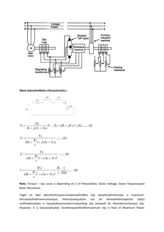
  • 1. Main InductionMotor Characteristics ; jXth jX2 Rth i2 + R2/s Vth - jXm Vth V 1 , Zth ( R1 jX 1) / / jXm …….. (1) R1 j ( X 1 Xm) Vth I2 …….. (2) R2 ( Rth ) j ( Xth X 2) s Vth 2 I 22 …….. (3) R2 2 ( Rth ) ( Xth X 2) 2 s 3Vth 2 R2 1 …….. (4) R2 2 ( Rth ) ( Xth X 2) 2 s 2 fs s Note :Torque – slip curve is depending on 3 of thevariables; Stator Voltage, Stator frequencyand Rotor Resistance. Toget an idea aboutthetorquecurvewemayfindthe slip valueforwhichtorque is maximum. Actuallytofindmaximumtorque, thetorqueequation can be derivedwithrespectto slip(s) andthederivation is equatedtozeroandcorresponding slip valuewill be themaximumtorque slip. However, it is toocomplicated. Anotherwaytofindthemaximum slip is Rule of Maximum Power
  • 2. Transfer, maximumtorque is satisfiedwhenthemaximumpower is transferedto R2/s resistance. Togetmaximumpowerto R2/s ; R2 abs( Rth j ( Xth X 2)) …….. (5) s Withthisequation; R2 st max …….. (6) Rth 2 ( Xth X 2) 2 3Vth 2 max …….. (7) 2 s ( Rth Rth 2 ( Xth X 2) 2 ) Note :Theequations 6 and 7 showsthatmaximumtorque is not depending on rotor resistanceandthe slip value at torquemaximumincreaseswithincreasing rotor resistance. Thusthetorque – speedcurveswhen an externalresistanceaddedtothe rotor terminalsare as below.
  • 3. Characteristics of Scherbius Machine; Scherbius Machine is actually a polyphasecommutatormachinewith 3 phase stator excitingwindingsand a commutator set in armature.The rotor is woundedsinglephase but designedtogive 3 phasevoltage;therefore, threesets ofcommutatorcarbonbrushesplaced 120 degrees apart electricallytofor 3 phaseoperation. The stator excitorwinding is energizedwiththe rotor current of the main inductionmachine. Theexcitorinducedemfmagnitude can be calculatedwiththefollowingwellknownformula; e 4.44 * * Ns * f …….. (8) Note :Theactualsignal is a sine wavewithfrequency f, thisformulagivesthemagnitude. Similarlyinducedemf in rotor commutatorswill be p E 4.44 * * Nr * n * …….. (9) 2 where Ns is effectivenumber of turns in stator windings Nr is effectivenumber of turns in rotor windings isfluxperpole f is thefrequency of stator excitingvoltage Note : Pleaseseethetopologyfor rotor and stator connections. Rotor and stator terminalsareconnectedeachothervia an autotransformerwithchangingturnsratio say Kt. Thus; E KT e Nr n p KT …….. (10) Ns f 2 Nr n p f Ns KT 2 Pleasenoticethatthefrequency is totallydepending on Kt , sincepolenumberandnumber of turnsvaluesareconstant. Moreover, since theScherbiusmachine rotor is coupledwith an auxiliaryinductionmachinethe n valuewill be nearlyconstant ( onlyverysmall slip changes). Thus, thefrequency is determinedbythetransformer tap postion.
  • 4. Note :IftheScherbius Machine was a slip ring machine, the rotor frequencywill be f –fr.However, commutatorschangesthereferenceframetosynchronouslyrotatingreferenceframewithspeedfr, whichwill in turngivestheoutputfrequency f (same as theonefor stator side). Note :Therecoveredenergyfrom main motor is convertedtomechanicaltorque at the rotor of Scherbius Machine, whichreturnstheenergytothemainswiththehelp of auxinductionmachine. Note :Thetopologyprovides a closedloopcontrol of rotor currentsuchthattherequiredspeed is alwaysconstantwithadjustedautotransformer tap position. REFERENCE :Adkins B.,Gibbs W. J. PolyphaseCommutatorMachines. 1951