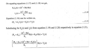
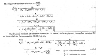
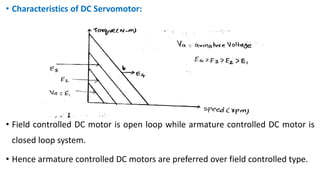
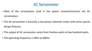
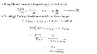
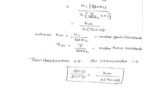
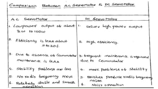
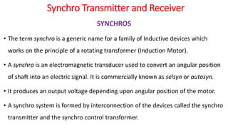
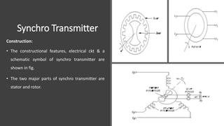
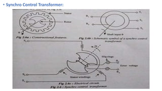
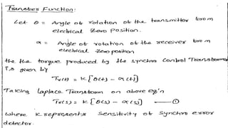
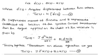
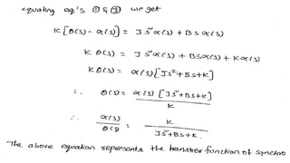
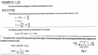
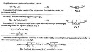
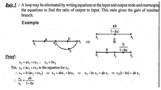
The document discusses transfer function representation of DC and AC servomotors. It provides details on the construction, working principle, and transfer function modeling of field controlled and armature controlled DC servomotors. It also discusses AC servomotor construction, torque-speed characteristics, and transfer function. Finally, it covers synchro transmitters and receivers, their working principles, and applications in angular position control from a remote location.
This document provides an overview of transformers and special machines. It discusses the construction, principle, and working of single phase transformers. It also covers autotransformers and gives the EMF equation. Special machines covered include stepper motors, including permanent and variable reluctance types. Servomotors are also discussed, including AC and DC types. Applications of transformers and different types of stepper and servo motors are briefly described.
1. Three phase induction motors operate using the principle of a rotating magnetic field produced by a three phase stator winding.
2. They have advantages over DC motors like low maintenance, ruggedness, and ability to operate in harsh environments.
3. Speed can be controlled by varying the frequency of the stator supply using a variable frequency drive to maintain a constant voltage-to-frequency ratio.
1. The document discusses different types of three phase induction motors, including their construction, operating principles, speed control methods, and applications.
2. It describes the key advantages of induction motors such as low maintenance, ruggedness, and ability to operate in harsh environments compared to DC motors.
3. Various starting methods for induction motors are explained, including star-delta starters and direct online starters to limit high starting currents.
This document discusses three phase induction motors. It describes their operating principle of rotating magnetic fields produced by three phase currents in the stator. Key points include:
- Induction motors operate on rotating magnetic fields and can run on single or three phase power, with three phase preferred.
- Advantages over DC motors include low maintenance, ruggedness, low cost, and ability to operate in harsh environments.
- Speed is controlled by varying supply frequency using variable frequency drives to maintain constant flux.
- Starters like star-delta are used to limit starting current and torque by initially applying reduced voltage.
The document discusses the principle of operation of a 3-phase alternator. It begins by explaining how synchronous generators work using Faraday's law of electromagnetic induction to generate AC voltages through relative motion of conductors and magnetic flux. It then describes the different types of synchronous machines, including those with salient poles and cylindrical rotors. The document goes on to explain the components and working of single-phase and three-phase alternators, how frequency depends on rotor speed and pole number, voltage regulation, and open/short-circuit characteristics. Power flow is described using equivalent circuit diagrams and the relationship between load angle and maximum power transfer is shown.
The document discusses the principle of operation of a 3-phase alternator. It begins by explaining how synchronous generators work using Faraday's law of electromagnetic induction to generate AC voltages through relative motion of conductors and magnetic flux. It then describes the different types of synchronous machines, including those with salient poles and cylindrical rotors. The document goes on to explain the components and working of single-phase and three-phase alternators, how voltage regulation is achieved, and it discusses open circuit, short circuit and load characteristics.
Slides of DC Machines with detailed explanationOmer292805
This document provides an overview of DC machines, including DC motors and generators. It discusses the basic components and principles of operation for DC machines. Some key points:
- DC machines convert mechanical energy to electrical energy (generators) or vice versa (motors). They are commonly used to drive industrial loads.
- The main parts are the stator, rotor/armature, commutator, and brushes. The commutator converts the AC voltage in the rotor to DC.
- DC motors operate by applying a DC current to the armature in a magnetic field, producing a torque via the Lorentz force. Speed and torque can be regulated by controlling field and armature circuits.
-
This document describes the principles of operation of a 3-phase alternator. It discusses how a synchronous generator works using Faraday's law of electromagnetic induction. It also describes the different components of a 3-phase alternator including the stator, rotor, and different winding configurations. The document also discusses how varying the field current can control the output voltage of the alternator and how the number of poles and rotor speed determine the output frequency. Open and short circuit testing characteristics are also summarized.
DC Machines with explanation in detail of everythingOmer292805
A DC motor chapter is summarized in 3 sentences:
DC machines can operate as motors or generators and include DC motors which use a DC power source and have a stationary field coil and rotating armature. The speed of a DC motor is proportional to its back EMF and inversely proportional to the armature current. Examples show how to calculate the speed of DC motors under different load conditions by determining the back EMF using the motor's equivalent circuit.
1) A DC motor runs on direct current electricity. It has a field winding that produces a magnetic field and an armature winding that rotates within this field.
2) In a DC motor, the armature experiences a force when current-carrying conductors are placed within a magnetic field, causing the armature to rotate.
3) DC motors can be shunt-wound, series-wound, or compound-wound depending on how the field and armature windings are connected. Shunt and series motors have different torque-speed characteristics.
This document provides information about understanding AC/DC motors and generators theory. It outlines the objectives, safety requirements, risk level, and evaluation criteria for a block of instruction. The instruction will cover fundamentals of rotating machines, different types of DC motors and generators, induction motors, and motor theory concepts. Students will be evaluated on an examination and must score 80% or higher to pass. Lab exercises will use Labvolt trainers to cover the topics.
This document discusses electric propulsion units used in electric vehicles and hybrid electric vehicles. It describes three main types of electric motors used: induction motors, permanent magnet brushless DC motors, and switched reluctance motors. For each motor type, the document covers basic operating principles, control methods, and applications in electric and hybrid vehicles. It also discusses losses in traction motors and inverters, as well as efficiency maps.
1. A DC motor runs on direct current electricity. It has a field winding that produces a magnetic field when energized, and an armature winding that rotates when placed in this magnetic field.
2. The key parts of a DC motor include the yoke, poles, field winding, armature core, armature winding, commutator, and brushes. The field winding produces flux, and the rotation of the armature winding within this flux induces voltage that is used to power the load.
3. DC motors can be shunt wound, series wound, or compound wound depending on how the field and armature windings are connected. Shunt and series motors have different torque-speed characteristics due
The document discusses permanent magnet brushless DC motors, including their construction with a permanent magnet rotor, electronic commutation instead of a mechanical commutator, and applications in automotive, industrial, computer and small appliance uses. It provides details on the operation, classifications based on pole arc and waveform, and common controller circuits used for permanent magnet brushless DC motors.
Torque produced by a DC motor is proportional to the product of current in the armature winding (Ia) and the magnetic field flux (Φ).
The flux is produced by the current in the field winding (If).
Therefore, Torque (T) ∝ Ia × If
For different types of DC motors, the field current If is related differently to the armature current Ia.
2. Derive the Speed equation for a DC Motor.
The document discusses the principles of operation of synchronous machines, which can operate as either motors or generators. It describes their construction, including salient pole and cylindrical rotors. It also covers single phase and three phase alternators, explaining how their windings produce phase-displaced voltages. Additional topics covered include open and short circuit characteristics, load conditions, equivalent circuits, and power flow calculations.
Chapter 7 Application of Electronic Converters.pdfLiewChiaPing
This document discusses power electronics applications in DC and AC drives. It describes the basic characteristics and equivalent circuits of DC motors and how their speed can be controlled through various single-phase and three-phase converter configurations. It also summarizes the operation of induction motors, including cage and slip-ring types, and how their speed can be controlled through variable frequency inverters or by adjusting the slip-ring voltage. The document concludes by outlining the main components of HVDC converter stations used for long distance and asynchronous power transmission.
The document discusses tachogenerators, which are devices that measure the speed of a rotating shaft by converting angular velocity into a voltage. There are two main types: DC tachogenerators, which generate a DC voltage corresponding to speed, and AC tachogenerators, which generate an AC voltage that must be rectified. Both work by inducing an electromotive force in a conductor based on its motion through a magnetic field, per Faraday's law of induction. Tachogenerators are used to measure speeds of electric motors, engines, and powered equipment.
This document provides information on drives, force, torque, inertia, speed, work, power, electrical power, DC circuits, AC circuits, AC motors, AC drives, and their operation and components. It discusses the basics of force, torque, inertia and their relationships. It also explains speed, work, power, horsepower, electrical power in DC and AC circuits. The document then covers the construction, nameplate, and operation of 3-phase AC motors. It concludes by describing the basics and components of AC drives including PWM technology, IGBTs, vector control and their parameters and commissioning.
This document provides information about different types of drives (actuation systems) including DC motors, AC motors, and stepper motors. It discusses the construction, working principles, advantages, disadvantages, and applications of each motor type. DC motors include brushed and brushless types. AC motors include synchronous and induction types. Stepper motors can be permanent magnet, variable reluctance, or hybrid synchronous types and operate by dividing a full rotation into discrete steps through electromagnetic pulses.
Study of Vector Control Algorithm and Inverter design for BLDC Motor, V/f con...Amol Mahurkar
This document summarizes a study on vector control algorithms and inverter design for BLDC motors. It discusses the objectives of studying BLDC motor operation, different control algorithms including vector control, and inverter design. It also covers V/F control of induction motors. Key topics covered include Clarke/Park transformations, sensorless control, inverter topologies, and a comparison of vector and V/F control techniques. The document is authored by engineering students and provides an overview of various motor control concepts and algorithms.
1) Synchronous generators have rotor windings that produce a rotating magnetic field and stator windings where 3-phase voltage is induced. They are driven by diesel engines, water turbines, or steam turbines.
2) The rotor magnetic poles can be either salient (sticking out) or cylindrical construction and are made of laminated steel to reduce eddy currents. Stator windings are used because connections are easier than on the rotating rotor.
3) Excitation systems use slip rings and brushes or brushless exciters to supply DC current to the rotor windings. This produced the rotating magnetic field needed to induce voltage in the stator windings.
Direct current motors slides with numericalOmer292805
A DC motor converts electrical energy into mechanical energy using a magnetic field and electricity to produce torque. It consists of a stator, armature, rotor, and commutator with brushes. Opposite magnetic fields inside the motor cause the rotor to turn, producing rotational motion. DC motors are commonly used in appliances and vehicles.
An induction motor is described with the following specifications:
- 480-V, 60 Hz, 50-hp, 3-phase
- Drawing 60A at 0.85 PF lagging
- Stator copper losses of 2 kW
- Rotor copper losses of 700 W
To determine the rotor frequency at full load, the slip is calculated using the given power rating, current, and power factor. The slip is then used to calculate the rotor frequency.
1. Three phase induction motors have a rotating magnetic field produced by a three phase stator winding that causes the rotor to turn.
2. The rotor can be either a squirrel cage (copper or aluminum bars short circuited by end rings) or wound construction.
3. Starters are used to reduce the starting current by lowering the supply voltage and improve starting torque by increasing rotor resistance during start up. Common starting methods include direct-on-line, star-delta, and auto transformer starters.
This document describes the components and operation of a DC motor. It discusses the stator, rotor, brushes, and commutator. It explains how current flowing through the rotor interacts with the magnetic field from the stator to generate torque. The document also covers different types of DC motors including permanent magnet, series, shunt, and compound wound motors. It provides equations for torque, speed, power, EMF, and terminal voltage.
1) The document discusses controlling DC motors using silicon-controlled rectifiers (SCRs). SCRs can be used in a circuit connected to a DC motor to control its speed.
2) Applying different voltages to the motor armature by controlling the gate current of SCRs allows variable speed control of the DC motor. Longer conduction times of the SCRs apply more voltage and increase motor speed.
3) Electronic control methods for DC motors include flux control, armature voltage control, open-loop speed control using rheostats, and closed-loop speed control using techniques like PI, PD, or PID control.
- A DC motor converts electrical energy into mechanical energy through electromagnetic principles. It has a rotor that rotates when current passes through the motor's armature winding within a magnetic field.
- The key components of a DC motor are the armature winding, field winding, commutator, and brushes. The field winding generates a magnetic field and the armature winding cuts this field to produce torque when powered.
- DC motors can be shunt wound, series wound, or compound wound depending on how the field winding is connected in relation to the armature winding. This determines the speed and torque characteristics of the motor.
Skip to main contentAccessibility help
Accessibility feedback
Google
digitals
Camera search
All
ImagesVideosMapsNewsMore
Tools
About 5,53,00,00,000 results (0.74 seconds)
Results for Pottipadu, Andhra Pradesh 521286
తెలుగులో
In English
(dĭj′ĭ-tl) 1. Anatomy Relating to or resembling a digit, especially a finger. 2. Expressed in numerical form, especially for use by a computer: converted the image to a digital form.
Digitals - definition of digitals by The Free Dictionaryhttps://www.thefreedictionary.com › digitals
About featured snippets
•
Feedback
Home | Digitals India | Your security is our highest priorityhttps://www.digitalsindia.com
Digitals India has installed Integrated Alarm system and CCTV in our 130 branches of our bank. Their service network & post-installation / AMC services are good ...
Contact Us · About us · Educational Institutions · Products
People also search for
digitals model
murthy digitals vijayawada phone number
digitals in kpop
reliance digital
digitals medical
digitals meaning in telugu
Sairam Digitals, Arundalpet - Printing Services in Vijayawadahttps://www.justdial.com › Vijayawada › Sairam-Digital...
Sairam Digitals in Arundalpet, Vijayawada is one of the leading businesses in the Printing Services with 33 photos. Also known for Flex Printing Services, ...
Rating: 4.5 · 2 votes
Digital Seva - Common Service Centreshttps://digitalseva.csc.gov.in
Places
Map of digitals
SS DIGITAL PHOTO STUDIO&VEDIO
No reviews · Photography Institute
Telaprolu, Andhra Pradesh · 099129 88819
Open ⋅ Closes 7PM
Directions
Sri Srinivasa Digitals
4.7
(6) · Digital printer
Vijayawada, Andhra Pradesh · Near Sai Priyanka Restaurant and coffee shop · 085005 90375
Open ⋅ Closes 10PM
Directions
Pc digital photo studio
No reviews · Photography studio
Madiga Gudem, Andhra Pradesh
Open ⋅ Closes 10PM
Directions
More places
Digitals India @ Amazon.in:https://www.amazon.in › ...
Online shopping from a great selection at Digitals India Store.
Reliance Digital: Online Electronic Shopping Store in Indiahttps://www.reliancedigital.in
Buy Electronics Online at India's Best Online Electronic Shopping Store, Reliance Digital. Shop laptops, tvs, mobiles, cameras, home appliances etc from top ...
What is digital? | Definition from TechTargethttps://www.techtarget.com › whatis › definition › digital
Digital describes electronic technology that generates, stores, and processes data in terms of two states: positive and non-positive.
Digital Definition & Meaning - Merriam-Websterhttps://www.merriam-webster.com › dictionary › digital
21-Dec-2022 — The meaning of DIGITAL is of, relating to, or utilizing devices constructed or working by the methods or principles of electronics ...
Images for digitals
modelling
img model
model agency
male
bella hadid
kendall jenner
polaroids
logo
female model
full body
iphone model
next model
meghan roche
gigi hadid
commercial model
fashion model
portfolio model
mens model
naomi
kaia gerber
Image re
Digitals India
HOME
ABOUT US
PRODUCTS
SOLUTIONS
SUPPORT
CONTACT US
CAREERS
Digital India Security Products
Previous
Next
OUR STRENGTH
Experienced, Expertise, Manufacturing, Service Network blend with customized solutions. Authoritatively coordinated.
15 Regional Offices
15 REGIONAL OFFICES
With our head office in Delhi-NCR, We are present at more than 15 locations Pan India.
38 Year Experience
38 YEAR EXPERIENCE
Our journey started 38 years ago and till now we have been the market pioneer and hold a firm ground with our customized services.
In House R&D
IN HOUSE R&D
The key consideration is our In-house R&D. Specialised & professional in-house research capability
NABL Certified
NABL CERTIFIED
With Utmost proud and confidence, we say, Our products are certified by National Accreditation Board for Testing & Calibration Laboratories.
Pan India Network
PAN INDIA NETWORK
Our 15 regional offices, our rich experience and Head office at Delhi-NCR extend our network to pan India.
Robust Product
ROBUST PRODUCT
We understand our Indian terrain is slightly different and we manufacture products in sync to our country requirements
OUR PARTNERS
OUR PRODUCTS
BRANDS
SOLUTIONS
Financial Institution Solutions
FINANCIAL INSTITUTION SOLUTIONS
Ranging from Branch security to ATM security and your cash van security and one central control.
Explore >>
Corporate and Enterprises
CORPORATE AND ENTERPRISES
Surveillance stands as the critical need for all of the corporates and all the enterprises.
Explore >>
Educational Institutions
EDUCATIONAL INSTITUTIONS
With all the play schools and schools where the childrens are present even universities are guarded.
Explore >>
Hospitals and Pharmaceutical
HOSPITALS AND PHARMACEUTICAL
Entry/exit points and proper security of the hospitals is the top priority
Explore >>
Industries
INDUSTRIES
From Entry/Exit management to the parking and security of the warehouses is the need of today.
Explore >>
Shopping and Retail
SHOPPING AND RETAIL
The loses incurred by the staff in warehouses and the cashier frauds and theft result in big numbers
Explore >>
High Value Goods
HIGH VALUE GOODS
Security for your high value articles stored or being transported
Explore >>
Financial Solutions
FINANCIAL SOLUTIONS
Ranging from Branch security to ATM security and your cash van security and one central control.
Explore >>
CLIENT TESTIMONIALS
LATEST FROM BLOG
MORE THAN
21,429
Home Guarded
MORE THAN
4,286
People Protected
MORE THAN
5,143
Events Covered
HEAD OFFICE
Digitals India Security Products Pvt. Ltd. C-22, Sector-63, Noida-201301, India
CALL US
+ 91 120-4202273
EMAIL US
info@digitalsindia.com
Digital India Logo
Backed by quality and proven by experience, Digitals India Security Products Pvt Ltd is ISO 9001:2015 certified and has over three decades of experience in the security industry.
Quick Links
Home
About us
Blog
Contact Us
Products
Solutions
Corporates And Enterprises
Educational Institutions
Financial Solutions
High Value
Skip to main contentAccessibility help
Accessibility feedback
Google
topics faculty orientation for electronics & communication department
Camera search
All
ImagesNewsVideosBooksMore
Tools
About 1,12,00,000 results (0.42 seconds)
Did you mean: topics faculty orientation for electronics and communication department
Orientation Lectures - Department of ECEhttps://www.kluniversity.in › ece
S.No. Date Research Group Delivered by
1 18‑Jul‑20 SPRG Dr. N. Siddaiah
2 30‑Jul‑20 CSRG Dr. R. Revathi
3 1‑Aug‑20 MERG Mrs. Mariya Priyadarshini
View 38 more rows
People also ask
What are the topics in ECE?
What do they teach in Electronics and communication?
Which subject is important for Electronics and communication?
Feedback
Faculty Orientation Workshop On SE (E&TC/Elex) Revised ...https://engg.kkwagh.edu.in › EC_FOW_report
PDF
June2020. The objective of this workshop was to orient all the faculty members towards the revised syllabus of. SE (E&TC/Elex) and to bring in uniformity in ...
7 pages
Online Orientation Programme - Electronics and ...https://ec.nirmauni.ac.in › news-events › online-orientat...
The Department of Electronics and Communication Engineering organised a two-days Online Orientation Programme for the students of B Tech, Semester III, V, ...
Department of Electronics and Communication Engineeringhttps://www.juit.ac.in › NBA_files › ECENBA_PR...
PDF
All advanced and elective courses of electronics & communication engineering. Multidisciplinary subjects, group discussions, co-curricular activities.
75 pages
Orientation Program for Students of Second Year Electronics ...https://dbcegoa.ac.in › orientation-program-for-students...
The orientation was conducted with the intention of welcoming the students to the ETC Department and introducing them to the various technical and non-technical ...
Electronics and Communication Engineeringhttp://simat.ac.in › Departments
PEO1: Exhibit their innovative ideas and management skills to analyse, design, develop and implement electronic systems or equipment. PEO2: Apply knowledge in ...
Departments >> Electronics and Communication Engghttps://www.bitmesra.ac.in › Show_Department_Section
10-Oct-2022 — Electronics and Communication Engineering · Instrumentation Engineering · Microwave Engineering · Wireless Communication · VLSI Design & Embedded ...
Electronics and Communication Engineeringhttp://uceou.edu › ece › ece
22-Mar-2019 — About Us. The Department of Electronics & Communication Engineering (ECE) was established in the year 1959 with only two faculty members. It ...
Department of Electronics and Communication Engineeringhttps://kanchiuniv.ac.in › academics › department-of-el...
CONTACT PERSON & ADDRESS · INTRODUCTION · VISION · MISSION · CURRICULAR ASPECTS · TEACHING-LEARNING AND EVALUATION · RESEARCH, CONSULTANCY AND EXTENSION.
Electronics & Communication Engineering - Meerut - MIEThttps://www.miet.ac.in › electronics-communication-engg
Since its inception in the year 2001, the ECE departm
Core industry experienced faculty to guide student projects.
Students participate in current research and sponsored projects.
Real time hands-on experience for students on sophisticated equipment and core area softwares.
Project based learning on the problems suggested by the industry.
Complete guidance to publish students work in reputed journals and magazines.
Students reach the societal problems and come out with innovative solutions.
Step by step guidance for student start-ups.
Financial support for students team to participate in national competitions.
Personal counsellor for every student.
Personalized training for core placements.
Student clubs for all-round personality development.
Open laboratories for students to work at anytime.
Exploring virtual laboratories from anywhere.
Core competitive exam trainings for interested students.
Complete support from the Professors for studies in abroad.
Continuous encouragement for extra curricular activities.
Timely opportunities for students to visit international universities.
Industry centric internships with good hands-on skilling.
Skill certifications in centres of excellence collaborated with NI instruments, CDAC, Tessolve semiconductor etc.
Mentors to guide students from industry and alumni.
Specializations
Under Grad Program-B.Tech
Internet of Things (IOT)
Renewable Energy & Smart Cities
VLSI
Robotics & Automation
Signal Processing
RF & Microwave
Data Communications
Computer communications & 5G Technologies
Bio-Medical Instrumentation
Artificial Intelligence & Intelligent Process Automation
Cyber Security & Block Chain Technology
Data Science & Big Data Analytics
Graphics, Gaming & UX Design
Post Grad Programs-M.Tech
RADAR & Communications
VLSI
IOT
Robotics & Automation
Why Join ECE in KLEF
Highlights
Established in 1983.
Contemporary industry ready curriculum.
Contemporary Industry-connect academic program.
100% placements for past 16 years for eligible and registered students.
Rich academic, research and industry experienced faculty
Innovative teaching pedagogies
State of the art laboratories, research centres and Centres of Excellence
Industry interactive collaboration
Student centric education
Skill based education.
ICT enabled classrooms.
International relations
Hall Marks
DST FIST Sponsored Department (Grant received twice).
Contemporary industry ready curriculum.
Lab taken to class.
100% placements for past 16 years for eligible and registered students.
248 rich academic, research and industry experienced faculty
50% faculty are Doctorates.
20+ faculty with Govt. of India research awards.
3000+ peer reviewed research papers published in Scopus/SCI/WOS/IEEE etc
42 government sponsored projects.
13.65 crores worth of sponsored projects.
33 books published by faculty.
48 patents published.
08 national & international granted patents.
18 Start-ups by students.
12 MoUs with industries
15+ well equippedAcademic laboratories
8 advanced research centres.
4 Centre of excellences with Industry
This document discusses state space analysis and related concepts. It defines state as a group of variables that summarize a system's history to predict future outputs. The minimum number of state variables required is equal to the number of storage elements in the system. These state variables form a state vector. The document also covers state space representation, diagonalization, solving state equations, the state transition matrix, and concepts of controllability and observability.
This document provides an introduction and overview of MATLAB. It discusses what MATLAB is, its main features and interfaces. Some key points covered include:
- MATLAB is a computing environment for doing matrix manipulations, calculations and data analysis. It has specialized toolboxes for tasks like signal processing and system analysis.
- The main interfaces are the command window, workspace, command history and editor window. Commands can be executed directly, through script files or custom functions.
- MATLAB handles matrices and vectors natively and has extensive math and graphics functions. Basic operations include matrix/vector creation, arithmetic, plotting and flow control structures.
- Help is available through the help menu, demos and documentation. Common functions covered
Main project-Image compression -ppt in 2003.pptRaviMuthamala1
This document discusses image compression and transmission through a digital communication system. It describes using DCT and DWT to compress images by removing coding redundancies. The compressed image is then transmitted through the digital communication system. BPSK modulation is used for signal modulation. Huffman and Shannon coding examples are provided for compression. The effects of quantization levels, number of diagonals, block size, and SNR and compression ratio are analyzed.
Use PyCharm for remote debugging of WSL on a Windo cf5c162d672e4e58b4dde5d797...shadow0702a
This document serves as a comprehensive step-by-step guide on how to effectively use PyCharm for remote debugging of the Windows Subsystem for Linux (WSL) on a local Windows machine. It meticulously outlines several critical steps in the process, starting with the crucial task of enabling permissions, followed by the installation and configuration of WSL.
The guide then proceeds to explain how to set up the SSH service within the WSL environment, an integral part of the process. Alongside this, it also provides detailed instructions on how to modify the inbound rules of the Windows firewall to facilitate the process, ensuring that there are no connectivity issues that could potentially hinder the debugging process.
The document further emphasizes on the importance of checking the connection between the Windows and WSL environments, providing instructions on how to ensure that the connection is optimal and ready for remote debugging.
It also offers an in-depth guide on how to configure the WSL interpreter and files within the PyCharm environment. This is essential for ensuring that the debugging process is set up correctly and that the program can be run effectively within the WSL terminal.
Additionally, the document provides guidance on how to set up breakpoints for debugging, a fundamental aspect of the debugging process which allows the developer to stop the execution of their code at certain points and inspect their program at those stages.
Finally, the document concludes by providing a link to a reference blog. This blog offers additional information and guidance on configuring the remote Python interpreter in PyCharm, providing the reader with a well-rounded understanding of the process.
Batteries -Introduction – Types of Batteries – discharging and charging of battery - characteristics of battery –battery rating- various tests on battery- – Primary battery: silver button cell- Secondary battery :Ni-Cd battery-modern battery: lithium ion battery-maintenance of batteries-choices of batteries for electric vehicle applications.
Fuel Cells: Introduction- importance and classification of fuel cells - description, principle, components, applications of fuel cells: H2-O2 fuel cell, alkaline fuel cell, molten carbonate fuel cell and direct methanol fuel cells.
The CBC machine is a common diagnostic tool used by doctors to measure a patient's red blood cell count, white blood cell count and platelet count. The machine uses a small sample of the patient's blood, which is then placed into special tubes and analyzed. The results of the analysis are then displayed on a screen for the doctor to review. The CBC machine is an important tool for diagnosing various conditions, such as anemia, infection and leukemia. It can also help to monitor a patient's response to treatment.
Discover the latest insights on Data Driven Maintenance with our comprehensive webinar presentation. Learn about traditional maintenance challenges, the right approach to utilizing data, and the benefits of adopting a Data Driven Maintenance strategy. Explore real-world examples, industry best practices, and innovative solutions like FMECA and the D3M model. This presentation, led by expert Jules Oudmans, is essential for asset owners looking to optimize their maintenance processes and leverage digital technologies for improved efficiency and performance. Download now to stay ahead in the evolving maintenance landscape.
Embedded machine learning-based road conditions and driving behavior monitoringIJECEIAES
Car accident rates have increased in recent years, resulting in losses in human lives, properties, and other financial costs. An embedded machine learning-based system is developed to address this critical issue. The system can monitor road conditions, detect driving patterns, and identify aggressive driving behaviors. The system is based on neural networks trained on a comprehensive dataset of driving events, driving styles, and road conditions. The system effectively detects potential risks and helps mitigate the frequency and impact of accidents. The primary goal is to ensure the safety of drivers and vehicles. Collecting data involved gathering information on three key road events: normal street and normal drive, speed bumps, circular yellow speed bumps, and three aggressive driving actions: sudden start, sudden stop, and sudden entry. The gathered data is processed and analyzed using a machine learning system designed for limited power and memory devices. The developed system resulted in 91.9% accuracy, 93.6% precision, and 92% recall. The achieved inference time on an Arduino Nano 33 BLE Sense with a 32-bit CPU running at 64 MHz is 34 ms and requires 2.6 kB peak RAM and 139.9 kB program flash memory, making it suitable for resource-constrained embedded systems.
Null Bangalore | Pentesters Approach to AWS IAMDivyanshu
#Abstract:
- Learn more about the real-world methods for auditing AWS IAM (Identity and Access Management) as a pentester. So let us proceed with a brief discussion of IAM as well as some typical misconfigurations and their potential exploits in order to reinforce the understanding of IAM security best practices.
- Gain actionable insights into AWS IAM policies and roles, using hands on approach.
#Prerequisites:
- Basic understanding of AWS services and architecture
- Familiarity with cloud security concepts
- Experience using the AWS Management Console or AWS CLI.
- For hands on lab create account on [killercoda.com](https://killercoda.com/cloudsecurity-scenario/)
# Scenario Covered:
- Basics of IAM in AWS
- Implementing IAM Policies with Least Privilege to Manage S3 Bucket
- Objective: Create an S3 bucket with least privilege IAM policy and validate access.
- Steps:
- Create S3 bucket.
- Attach least privilege policy to IAM user.
- Validate access.
- Exploiting IAM PassRole Misconfiguration
-Allows a user to pass a specific IAM role to an AWS service (ec2), typically used for service access delegation. Then exploit PassRole Misconfiguration granting unauthorized access to sensitive resources.
- Objective: Demonstrate how a PassRole misconfiguration can grant unauthorized access.
- Steps:
- Allow user to pass IAM role to EC2.
- Exploit misconfiguration for unauthorized access.
- Access sensitive resources.
- Exploiting IAM AssumeRole Misconfiguration with Overly Permissive Role
- An overly permissive IAM role configuration can lead to privilege escalation by creating a role with administrative privileges and allow a user to assume this role.
- Objective: Show how overly permissive IAM roles can lead to privilege escalation.
- Steps:
- Create role with administrative privileges.
- Allow user to assume the role.
- Perform administrative actions.
- Differentiation between PassRole vs AssumeRole
Try at [killercoda.com](https://killercoda.com/cloudsecurity-scenario/)
1. Transfer Function Representation
Transfer Function of DC Servomotor
• DC servomotor is essentially an ordinary DC motor except with very few
variations in its constructional features.
• It gives quick response to control signals & possess low Inertia and high starting
torque.
• Two different modes in which the DC motor can be operated are
1. Field Controlled Mode
2. Armature Controlled Mode
2. 1. T.F of Field Controlled DC servomotor
• The speed of the DC motor is directly proportional to armature voltage and inversely
proportional to the flux.
• In field controlled DC motor the armature voltage is kept constant and speed is varied
by varying the flux of the machine.
• Since flux is directly proportional to field current, the flux is varied by varying the field
current.
• The speed control system is an electromechanical control system.
• The electrical system consists of armature & field ckt but for analysis purpose, only
field ckt is considered bcoz the armature is excited by by a constant voltage.
3. • The mechanical system consists of the rotating part of the motor and the load
connected to the shaft of the motor.
• The field controlled DC motor speed control system is shown below.
4. • Let,
• The equivalent ckt of field is
• By KVL, we can write
5. • The torque of DC motor is proportional to product of flux and armature current.
• Since armature current is constant in this system, the torque is proportional to
flux alone, but flux is proportional to field current.
i.e
• The mechanical system of the motor is shown in below fig.
• The differential eqn governing the system of motor is
6.
7.
8. 2. T.F of Armature Controlled DC servomotor
• The speed of the DC motor is directly proportional to armature voltage and inversely
proportional to the flux.
• In armature controlled DC motor the desired speed is obtained by varying the
armature voltage.
• This speed control system is an electromechanical control system.
• The electrical system consists of armature and the field ckt but for analysis purpose,
only the armature ckt is considered bcoz the field is excited by a constant voltage.
• The mechanical system consist of the rotating part of the motor & load connected to
the shaft of the motor.
9. • The armature controlled DC motor speed control system is shown below.
• Let,
10. • The equivalent ckt of armature is
• By KVL, we can write
• The torque of DC motor is proportional to product of flux and armature current.
• Since the flux is constant in this system, the torque is proportional to armature
current alone.
i.e
11. • The mechanical system of the motor is shown in fig.
• The differential eqn governing the mechanical system of the motor is given by,
• The back emf of DC machine is proportional to speed (angular velocity) of shaft.
12.
13.
14.
15. • Characteristics of DC Servomotor:
• Field controlled DC motor is open loop while armature controlled DC motor is
closed loop system.
• Hence armature controlled DC motors are preferred over field controlled type.
16. AC Servomotor
• Most of the servomotors used in low power servomechanisms are AC
servomotors.
• The AC servomotor is basically a two-phase induction motor with some special
design features.
• The output of AC servomotor varies from fraction watts to few hundred watts.
• The operating frequency is 50Hz to 400Hz.
17. Construction:
• It is mainly divided into two parts namely stator & rotor.
Stator:
• The stator carries two windings uniformly distributed and displayed by 90o in space.
• One winding is called main winding, this is excited by a constant voltage AC supply.
• The other winding is called control winding, it is excited by variable control voltage
which is obtained from a servoamplifier.
• This voltage is 90o out of phase with respect to the voltage applied to the reference
winding.
18. • The stator of the AC servomotor is shown below.
19.
20. • The other type of rotor is drag cup type
rotor. There are two air gaps in such
construction.
• Such construction reduces Inertia
considerably and hence such type of
rotor is used in very low power
applications.
• The Aluminium is used for the cup
construction.
• The construction is shown in fig.
21. Torque Speed Characteristics:
• The Torque – speed characteristics of
two phase induction motor mainly
depends on the ratio of reactance to
resistance.
• For small X to R ratio i.e high
resistance and low reactance motor,
the characteristics are much more
linear while it is non-linear for large X
to R ratio as shown in fig(d).
22. • In practice design of the motor is so as to get almost linear
torque-speed characteristics.
• The fig(e) shows the torque-speed characteristics for various
control voltages.
• The torque varies almost linearly with speed.
• All the characteristics are equally spaced for equal increments
of control voltages.
• It is generally operated with low speeds.
• AC servo motors widely used in Instrument
Servomechanisms, remote positioning devices, process
control systems, self balancing recorders, computers tracking,
guidance systems, robotics & machine tools, etc.,
23. Transfer Function of AC Servomotor
• Let,
Tm = Torque developed by Servomotor
Ɵ = Angular displacement of rotor
ω =
𝑑𝜃
𝑑𝑡
= Angular speed
TL = Torque required by the load
J = Moment of Inertia of load and the rotor
B = Viscous – frictional coefficient of load and the rotor
K1 = Slope of control phase voltage Vs Torque characteristics
K2 = Slope of speed – torque characteristics
24. • With reference to fig(e), we can say that for speeds near zero all the curves are
straight lines parallel to the Torque at rated i/p voltage (ec = E) and are equally
spaced for equal increments of i/p voltage.
• Under this assumption the torque developed by the motor is represented by
the equation
Torque developed by motor Tm = --------- (1)
• The rotating part of motor & the load can be modelled by the equation
TL =
25. • At equilibrium the motor torque is equal to load torque
------------- (3)
• On taking L.T of eqn(3) with zero initial conditions, we get
26.
27.
28. Synchro Transmitter and Receiver
SYNCHROS
• The term synchro is a generic name for a family of Inductive devices which
works on the principle of a rotating transformer (Induction Motor).
• A synchro is an electromagnetic transducer used to convert an angular position
of shaft into an electric signal. It is commercially known as selsyn or autosyn.
• It produces an output voltage depending upon angular position of the motor.
• A synchro system is formed by interconnection of the devices called the synchro
transmitter and the synchro control transformer.
29. • They are also called synchro pair.
• The synchro pair measures & compares two angular displacements and its
o/p voltage is approximately linear with angular difference of the axis of both
the shafts.
• They can be used in the following two ways.
1. To control the angular position of load from a remote place/ long distance.
2. For automatic correction of changes due to disturbance in the angular
position of the load.
30. Synchro Transmitter
Construction:
• The constructional features, electrical ckt & a
schematic symbol of synchro transmitter are
shown in fig.
• The two major parts of synchro transmitter are
stator and rotor.
31. • The stator is made up of laminated silicon steel and slotted on the inner
periphery to accommodate a balanced 3-phase winding.
• The stator winding is concentric type with the axis of 3 coils 120o apart. The
stator winding is star connected i.e Y-connection.
• The rotor is of dumb bell construction with a single winding.
• The ends of rotor winding are terminated on two slip rings.
• A single phase ac excitation voltage is applied to rotor through slip rings.
32. Working Principle:
• When the rotor is excited by ac voltage, the rotor current flows , and a magnetic field is produced.
• The rotor magnetic field induces an emf in the stator coils by transformer action.
• The effective voltage induced in any stator coil depends upon the angular position of the coil’s axis w.r.t rotor
axis.
Let, er = Instantaneous value of AC voltage applied to rotor.
es1,es2, es3 = Instantaneous value of emf induced in stator coils S1, S2, S3 w.r.t neutral respectively.
Er = Maximum value of rotor excitation voltage.
ω = Angular frequency of rotor excitation voltage.
Kt = Turns ratio of stator and rotor winding.
Kc = Coupling coefficient.
Ɵ = Angular displacement of rotor w.r.t reference.
33. Let, The instantaneous value of excitation voltage, er = Er Sinωt
• Let the rotor rotates in anticlockwise direction. When the rotor rotates by an angle Ɵ,
emfs are induced in stator coils.
• The frequency of induced emf is same as that of rotor frequency.
• The magnitude of induced emfs are proportional to the turns ratio and coupling
coefficient.
• The turns ratio, Kt is a constant, but coupling coefficient, Kc is a function of rotor
angular position.
Therefore, Induced emf in stator coil = Kt Kc Er sin ωt ---------(1)
34. • When Ɵ=0, the flux linkage of coil S2 is maximum and when Ɵ= 90o, the flux
linkage of coil S2 is zero. Hence the flux linkage of coil S2 is function of CosƟ.
• The flux linkage of coil S3 ill be maximum after rotation of 120o in
anticlockwise direction and that of S1 after a rotation of 240o
.
Therefore, Coupling coefficient, Kc for coil -S2 = K1 CosƟ ----------(2)
Coupling coefficient, Kc for coil -S3 = K1 Cos(Ɵ-120o) --------(3)
Coupling coefficient, Kc for coil -S1 = K1 Cos(Ɵ-240o) ---------(4)
35. • Hence the emfs of stator coils w.r.t Neutral can be expressed as follows.
es2 = K1 Kt CosƟ ErSinωt = K Er CosƟ Sinωt ---------(5)
es3 = K1 Kt Cos(Ɵ-120o) ErSinωt = K ErCos(Ɵ-120o) Sinωt ------(6)
es1 = K1 Kt Cos(Ɵ-240o) ErSinωt = K ErCos(Ɵ-240o) Sinωt ------(7)
• With reference to fig. by KVL the coil-to-coil emf can be expressed as
es1s2 = es1 - es2 = √3 K Ersin(Ɵ+240o) Sinωt -------- (8)
es2s3 = es2 - es3 = √3 K Ersin(Ɵ+120o) Sinωt ---------(9)
es3s1 = es3 - es1 = √3 K ErsinƟ Sinωt ---------(10)
36. • When Ɵ=0, from eqn5 we can say that maximum emf is induced in coil S2.
• But from eqn10 it is observed that th ecoil-to-coil voltage es3s1 is zero.
• This position of the rotor is defined as the electrical zero of the transmitter.
• The electrical zero position is used as reference for specifying the angular position of
rotor.
• The i/p to syncho transmitter is the angular position of its rotor shaft and the o/p is a
set of 3 stator coil-to-coil voltages.
• By measuring & identifying the set of voltages at the stator terminals, it is to identify
the angular position of the rotor.
• A device called synchro/digital converter is available to measure the stator voltages &
to calculate the angular measure and then display the direction & angle of rotation.
43. Block Diagram Representation of Electrical Systems
• Electrical systems contain mainly three
basic elements — resistor, inductor and
capacitor.
• Consider a serries off RLC circuit as
shown in the following figure. Where,,
Vi(t) and Vo(t) are the input and output
voltages.
• Let i(t) be the current passing through
the circuit. This circuit is in time domain.
44. • By applying the L.T to this circuit, will get the circuit in s-domain.
• The circuit is as shown in the following figure.
• From the above ckt, we can write
45. • Let us now draw the block diagrams for these two equations individually. And
then combine those block diagrams properly in order to get the overall block
diagram of series off RLC Circuit (s--domain).
46. • Equation 1 can be implemented with a block having the transfer function,
• The input and output of this block are
• We require a summing point to get
• The block diagram of Equation 1 is shown in the following figure.
47. • Equation2 can be implemented with a block having transfer function,
• The input and output of this block are
• The block diagram of Equation 2 is shown in the following figure.
• The overall block diagram of the series of RLC Circuit (s-domain) is shown in the
following figure.
48.
49. • Similarly,, you can draw the block diagram of any electrical circuit or system
just by following this simple procedure.
• Convert the time domain electrical circuit into an s-domain electrical circuit by
applying L.T.
• Write down the equations for the current passing through allll series branch
elements and voltage across all shunt branches.
• Draw the block diagrams for all the above equations individually.
• Combine all these block diagrams properly in order to get the overall block
diagram of the electrical circuit (s-domain).
50. Block Diagram Algebra
• A Block Diagram of a system is a pictorial representation of the functions
performed by each component and of the flow of signals.
• A control system may consists of three elements for its block diagram.
• They are
1. Block
2. Branch Point
3. Summing Point
51. • Block:
• In a block diagram all the system variables are linked to each other through
functional blocks.
• The functional block or simply block is a symbol for the mathematical operation
on the input signal to the block that produces the output.
• The transfer function of a component is represented by a block. Block has single
input and single output.
52. • Summing Points are used to add two or more
signals in the system.
• A Branch Point/Take off point is a point from
which the signal from a block goes concurrently
to other blocks or summing points.
53. Constructing Block Diagram for Control Systems
• A control system can be represented diagrammatically by block diagram.
• The Diff.Eqns governing the system are used to construct the block diagram.
• By taking L.T the D.Eqns are converted to algebraic eqns. The eqns will have variables &
constants.
• From the working knowledge of the system the i/p and o/p variables are identified and the
block diagram for each eqn can be drawn.
• Each eqn gives one section of block diagram. The o/p of one section will be i/p to the other
section.
• The various sections are interconneced to obtain the overall block diagram of the system.
54.
55.
56.
57.
58.
59. Block Diagram Reduction
• The block diagram can be reduced to find the overall T.F of the system.
• The following rules can be used for block diagram reduction .
• The rules are framed such that any modification made on the diagram does not
alter the input-output relation.
60.
61.
62.
63.
64.
65.
66.
67.
68.
69.
70.
71.
72.
73.
74.
75.
76.
77.
78.
79.
80.
81.
82.
83.
84.
85.
86.
87.
88. Signal Flow Graph(SFG)
• The SFG is used to represent the control system graphically and it was
developed by S.J.Mason.
• A SFG is a diagram that represents a set of simultaneous linear algebraic eqns.
• By taking L.T, the time domain D.Eqns governing a control system can be
transferred to a set of algebraic eqns in s-domain.
• The SFG & the block diagram approach yields the same information.
• The advantage of SFG is that, using Mason’s gain formula the overall gain of the
system can be computed easily.
89. • The SFG depicts the flow of signals from one point of system to another & gives the
relationship among the signals.
• A SFG consists of a n/w in which nodes are connected by directed branches.
• Each node represents a system variable & each branch connected b/w two nodes acts
as a signal multiplier.
• Each branch has a gain or transmittance. When signal passing through a branch, it gets
multiplied by the gain of the branch.
• In SFG, the signal flows in only one direction.
• The direction of signal flow is indicated by an arrow placed on the branch & the
gain(multiplication factor) is indicated along the branch.
90.
91.
92.
93.
94.
95. SFG Reduction
• The SFG of a system can be reduced either by using rules of a SFG algebra or by
using Mason’s Gain Formula.
• For SFG reduction using rules of SFG, write eqns at every node and then
rearrange these eqns to get the ratio of output & input.(T.F)
• The SFG reduction by above method will be time consuming & tedious.
• S.J.Mason has developed a simple procedure to determine the T.F of the system
represented as a SFG.
• He has developed a formula called by his name Mason’s gain formula which can
be directly used to find the T.F of the system.
96. Mason’s Gain Formula
• The Mason’s Gain Formula is used to determine the T.F of the system from the
SFG of the system.
• Let, R(s) = Input to the system
C(s) = Output of the system
Now, T.F of the system, T(s) = C(s)/R(s)
• Mason’s Gain formula states the overall gain of the system (T.F) as follows,
Overall Gain,
97.
98. Constructing SFG for Control:
• The following procedure can be used to construct SFG of a system.
1. Take L.T of the Diff.Eqns governing the system in order to convert them into s-
domain.
2. The constants & variables of the s-domain equations are identified.
3. From the knowledge of the system, the variables are identified as input, output and
intermediate variables.
4. For each variable a node is assigned in SFG and constants are assigned as the gain or
transmittance of branches connecting the nodes.
5. For each eqn a SFG is drawn and then they are inrterconnected to give overall SFG of
the system.
99.
100.
101.
102.
103.
104.
105.
106.
107.
108.
109. Procedure for converting Block Diagram to SFG
• The following procedure can be used to convert Block diagram to SFG.
1. Assume nodes at i/p & o/p, at evry summing point, at every branch point and in
between cascaded blocks.
2. Draw the nodes separately as small circles & number the circles in the order 1, 2, 3,
….
3. From the block diagram, find the gain b/w each node in the main forward path and
connect all the corresponding ciclesby straight line and mark the gain b/w nodes.
4. Draw the feed forward paths b/w various nodes and mark the gain of feed forward
path along with sign.
5. Draw the f/b paths b/w various nodes and mark the gain of feed forward path along
with sign.
110.
111.
112.
113.
114.
115.
116.
117.
118.
119.
120.
121. Electrical Analogous of Mechanical Translational
Systems
• The 3 basic elements Mass, Dash-pot and Spring that are used in modelling mechanical
translational systems are analogous to Resistance, Inductance and Capacitance of
electrical system.
• The input Force in mechanical system is analogous to either voltage source or current
source in electrical systems.
• The output velocity in mechanical system is analogous to either current or voltage in an
element in electrical system.
• Since the electrical systems has two types of inputs either voltage or current source,
they are two types of analogies: 1. Force-Voltage and 2. Force-current analogy.
142. Electrical Analogous of Mechanical Rotational Systems
• The 3 basic elements moment of inertia, rotational dashpot and torsional spring
are used in modelling mechanical systems are analogous to resistance,
inductance and capacitance of electrical systems.
• The i/p torque in mechanical system is analogous to either voltage or current
sourse in electrical systems.
• The o/p angular velocity in mechanical system is analogous to either current or
voltage in an electrical system.
• Since the electrical systems has two types of inputs either voltage or current,
there are two types of analogies: Torque-Voltage and Torque-Current Analogy.