Download as PDF, PPTX
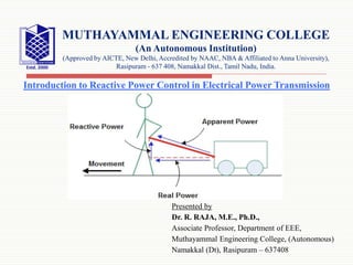
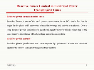


The document, presented by Dr. R. Raja, discusses reactive power control in electrical power transmission, defining reactive power as a component of AC power originating from the phase shift between voltage and current. It emphasizes the significance of reactive power in maintaining voltage levels for effective energy transfer in transmission systems, differentiating between true, reactive, and apparent power. The presentation further explains the relationship between voltage and current phase angles and their impact on active and reactive power.