Downloaded 24 times

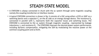
![The STATCOM is a shunt connected reactive power compensator device that is capable of
generating and/or absorbing reactive power. STATCOM consists of a voltage source converter that
form a given input of dc voltage produces a set of 3-phase ac output voltage each in phase and
coupled to the corresponding ac system voltage through a relatively small reactance. The device
voltage is provided by an energy storage capacitor.
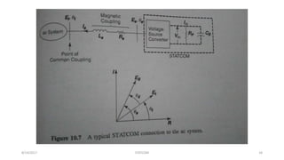
From fig; I =
𝑣 𝑠<Ө0 −𝑣<0
𝑗𝑋0
SSTATCOM =|V0| < Ө0 *𝐼∗
= V0<Ө0 *[
𝑣 𝑠<Ө0 −𝑣<0
𝑗𝑋0
]∗
=
𝑉0
2
−𝑉0 𝑉<Ө0
−𝑗𝑋
=
𝑉0 𝑉𝑠𝑖𝑛Ө0
𝑋
+ 𝑗
𝑉0
𝑋
(𝑉0 − 𝑉𝑐𝑜𝑠Ө0)
Now,
QSTATCOM =
𝑉0
𝑋
(𝑉0 − 𝑉𝑐𝑜𝑠Ө0)
8/14/2017 STATCOM 19](https://image.slidesharecdn.com/presentationaps-170814040654/85/STATCOM-19-320.jpg)
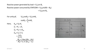
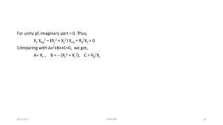
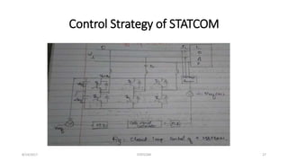

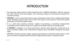
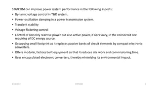
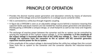
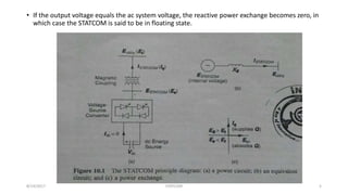
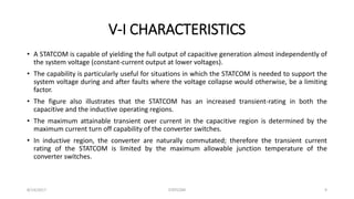
The document discusses STATCOM (Static Synchronous Compensator), which is a shunt connected reactive power compensation device capable of generating and absorbing reactive power using a voltage source converter. It can improve power system performance by providing dynamic voltage control, damping power oscillations, improving transient stability, and controlling voltage flickering and reactive/active power. The principle of operation involves using a voltage source converter to generate a balanced set of three sinusoidal voltages to exchange reactive power with the system by varying the amplitude and phase angle of the output voltage.


![[IJET V2I2P30] Authors: AnkurGheewala, Jay Chanawala,Nikhil Jadav,Modi Rishit...](https://cdn.slidesharecdn.com/ss_thumbnails/ijet-v2i2p30-160609050010-thumbnail.jpg?width=640&height=640&fit=bounds)


