Linear control systems unit 1 power point presentation
1.
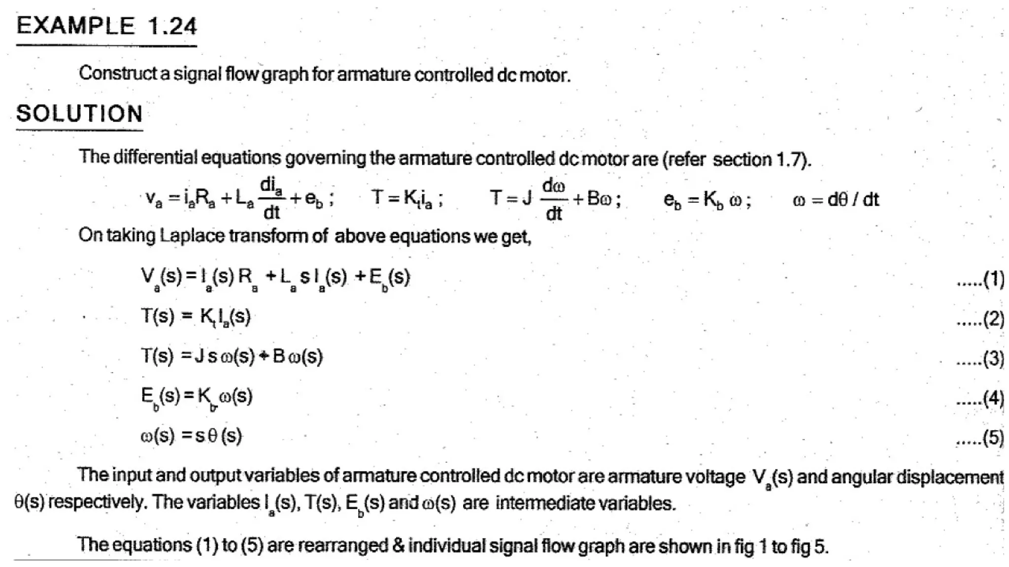
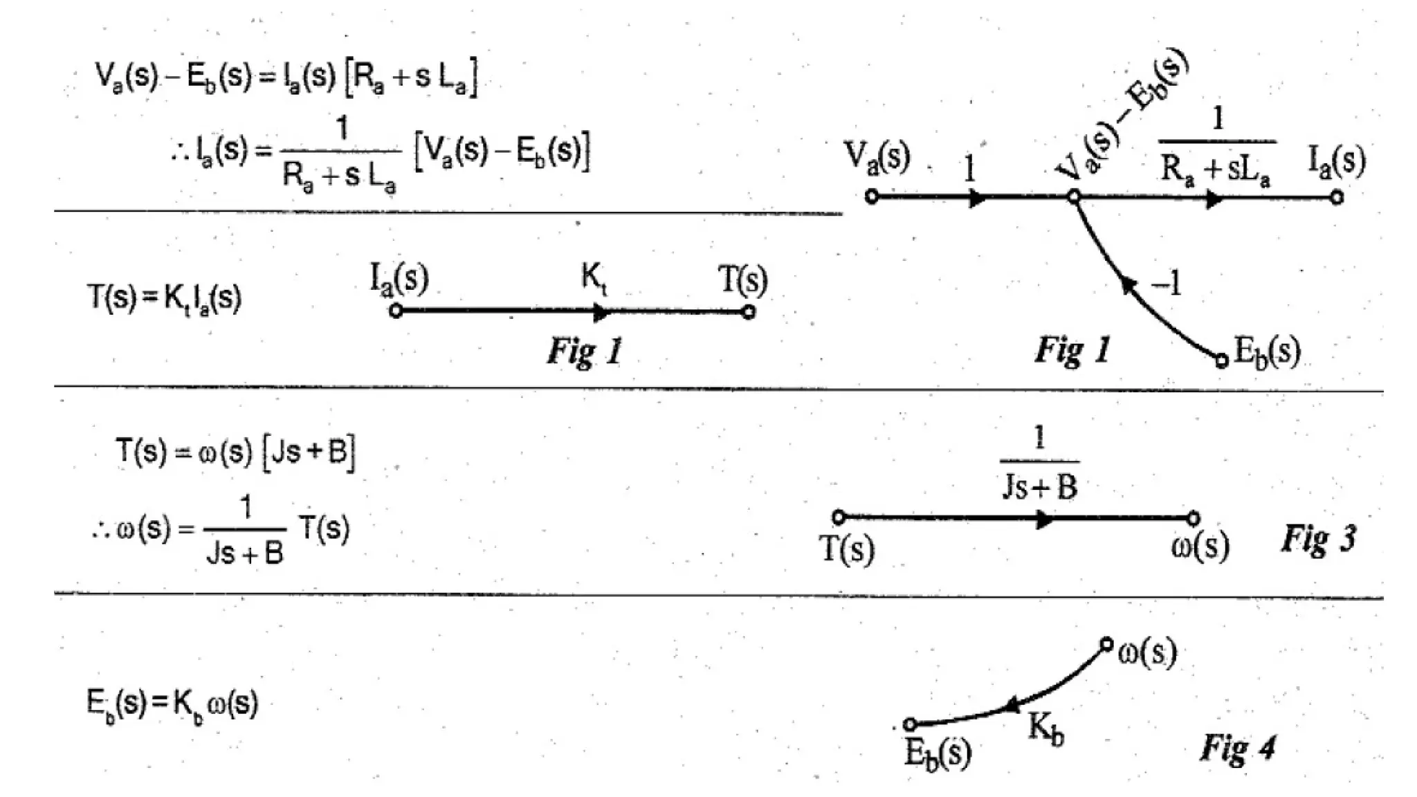
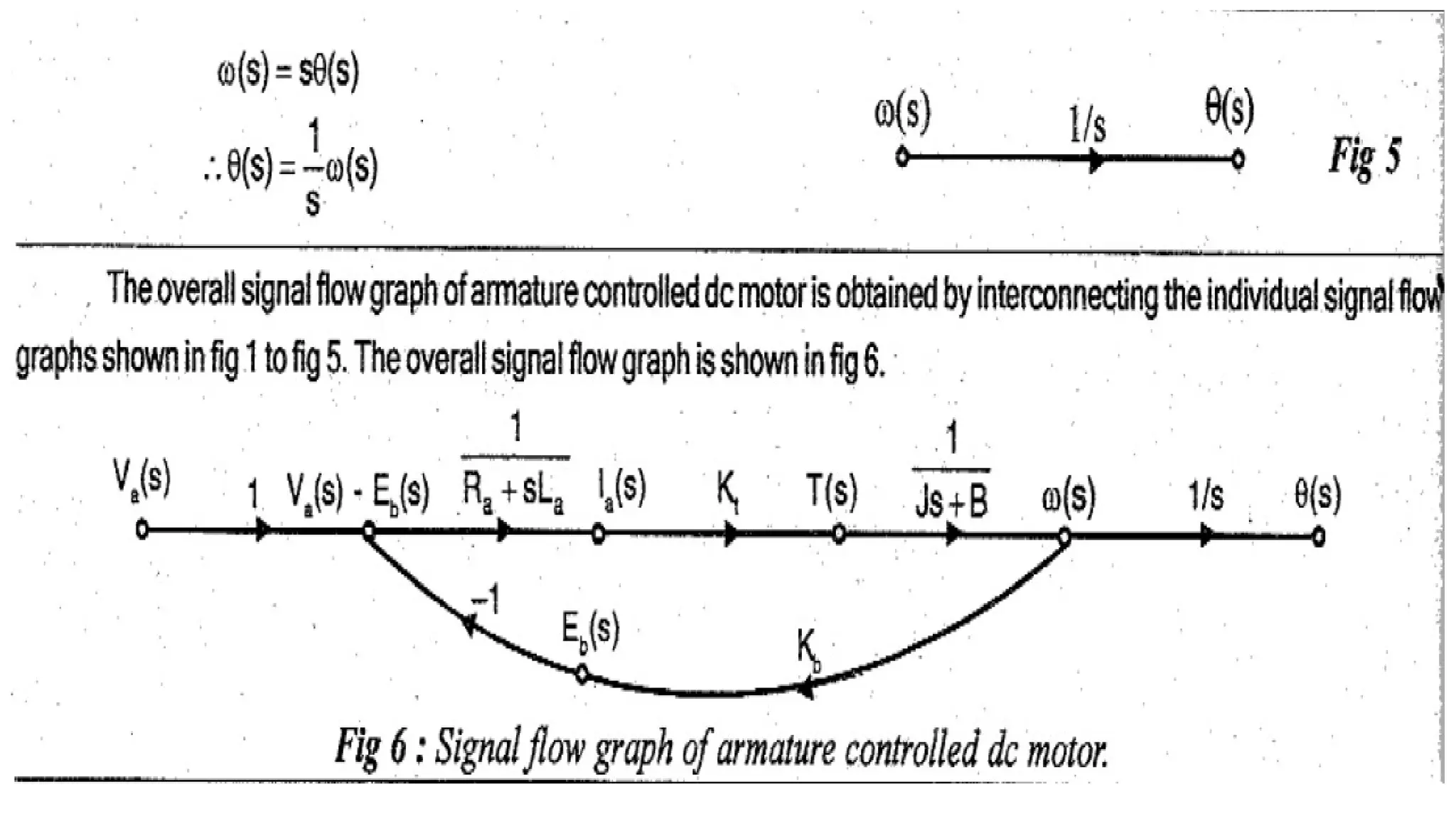
Transfer Function Representation
TransferFunction of DC Servomotor
• DC servomotor is essentially an ordinary DC motor except with very few
variations in its constructional features.
• It gives quick response to control signals & possess low Inertia and high starting
torque.
• Two different modes in which the DC motor can be operated are
1. Field Controlled Mode
2. Armature Controlled Mode
2.
1. T.F ofField Controlled DC servomotor
• The speed of the DC motor is directly proportional to armature voltage and inversely
proportional to the flux.
• In field controlled DC motor the armature voltage is kept constant and speed is varied
by varying the flux of the machine.
• Since flux is directly proportional to field current, the flux is varied by varying the field
current.
• The speed control system is an electromechanical control system.
• The electrical system consists of armature & field ckt but for analysis purpose, only field
ckt is considered bcoz the armature is excited by by a constant voltage.
3.
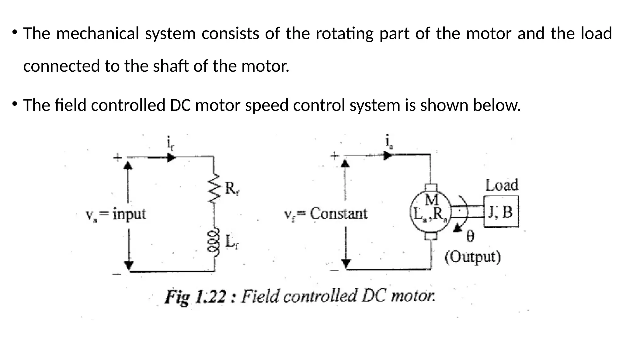
• The mechanicalsystem consists of the rotating part of the motor and the load
connected to the shaft of the motor.
• The field controlled DC motor speed control system is shown below.
4.
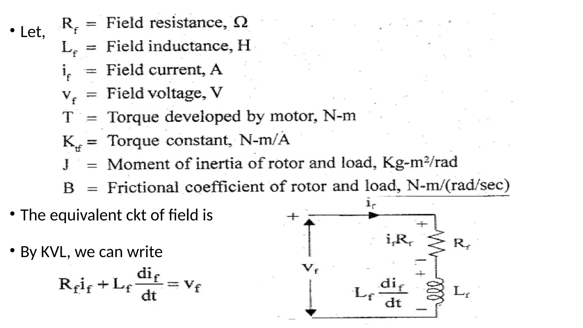
• Let,
• Theequivalent ckt of field is
• By KVL, we can write
5.
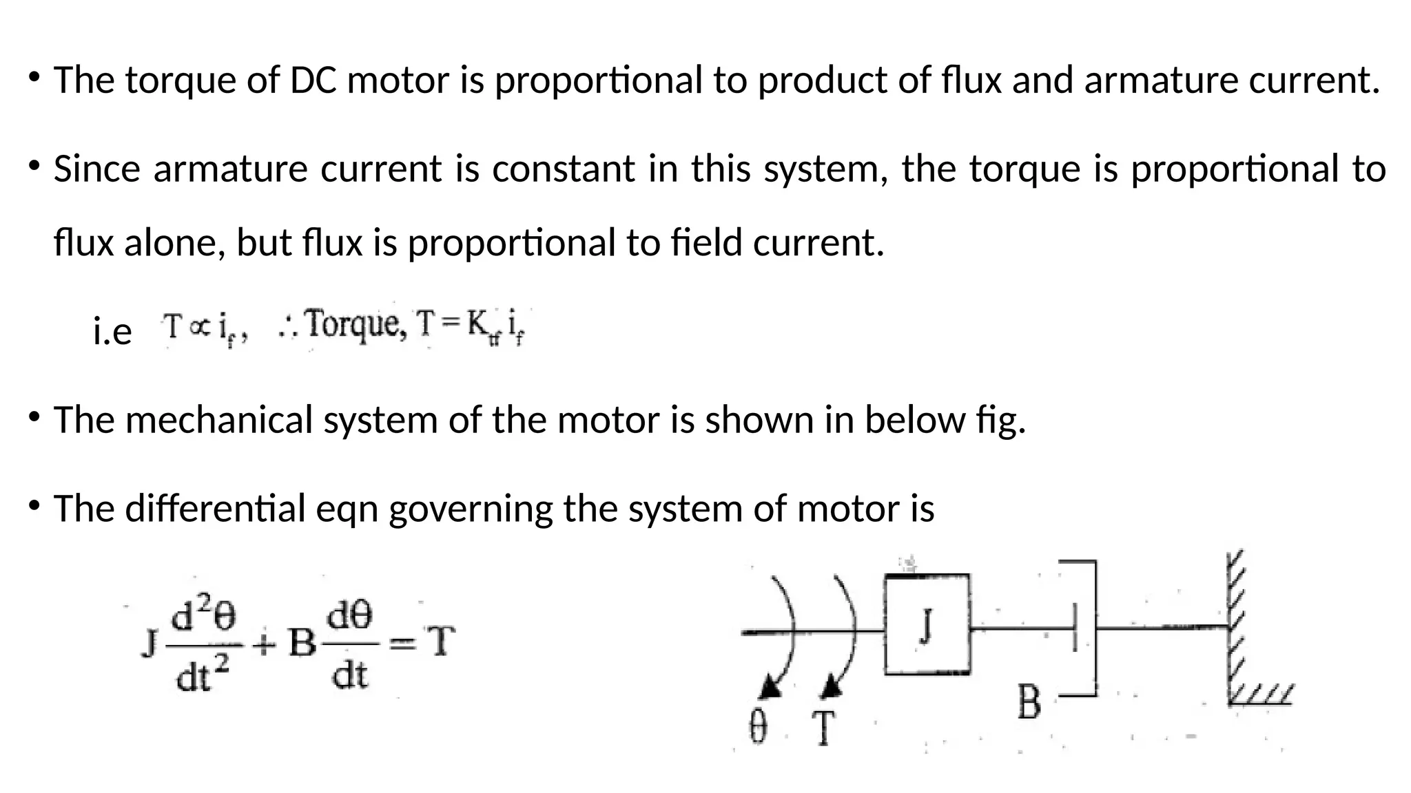
• The torqueof DC motor is proportional to product of flux and armature current.
• Since armature current is constant in this system, the torque is proportional to
flux alone, but flux is proportional to field current.
i.e
• The mechanical system of the motor is shown in below fig.
• The differential eqn governing the system of motor is
8.
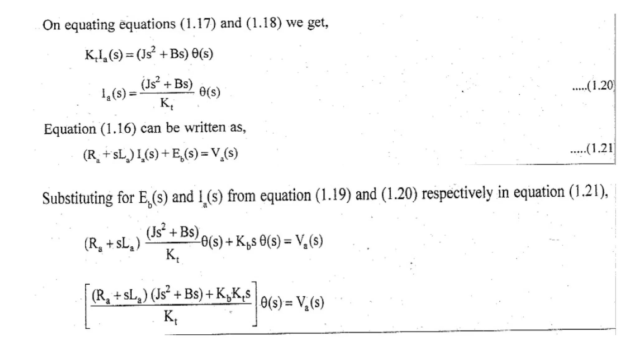
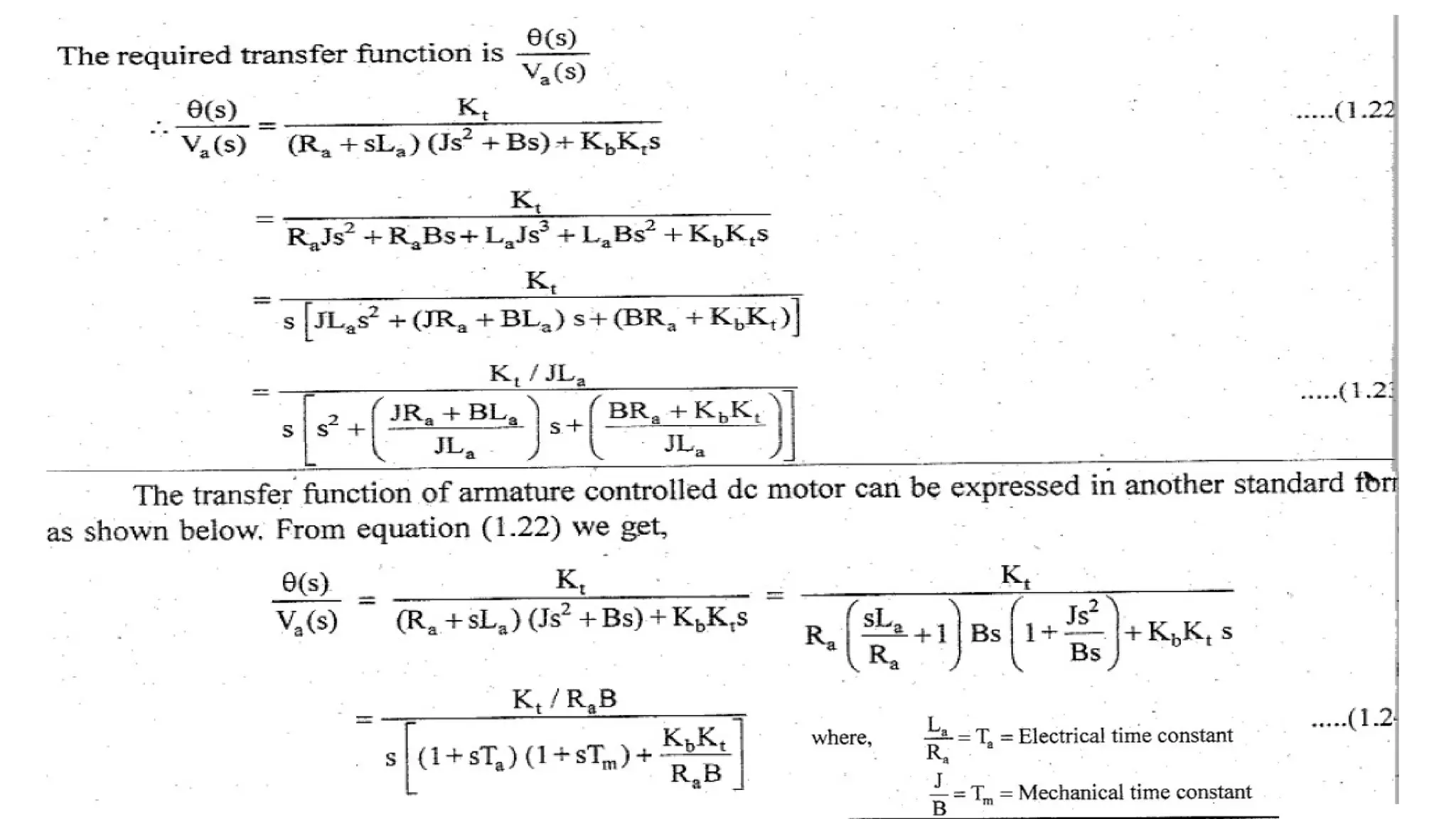
2. T.F ofArmature Controlled DC servomotor
• The speed of the DC motor is directly proportional to armature voltage and inversely
proportional to the flux.
• In armature controlled DC motor the desired speed is obtained by varying the
armature voltage.
• This speed control system is an electromechanical control system.
• The electrical system consists of armature and the field ckt but for analysis purpose,
only the armature ckt is considered bcoz the field is excited by a constant voltage.
• The mechanical system consist of the rotating part of the motor & load connected to
the shaft of the motor.
9.
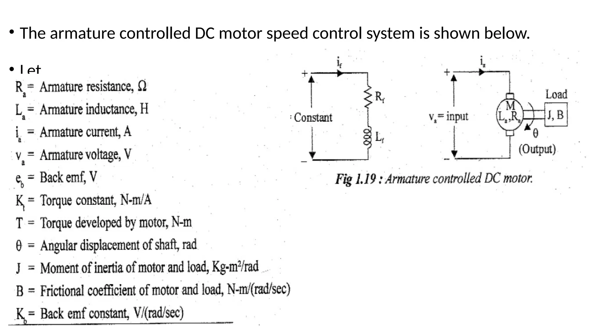
• The armaturecontrolled DC motor speed control system is shown below.
• Let,
10.
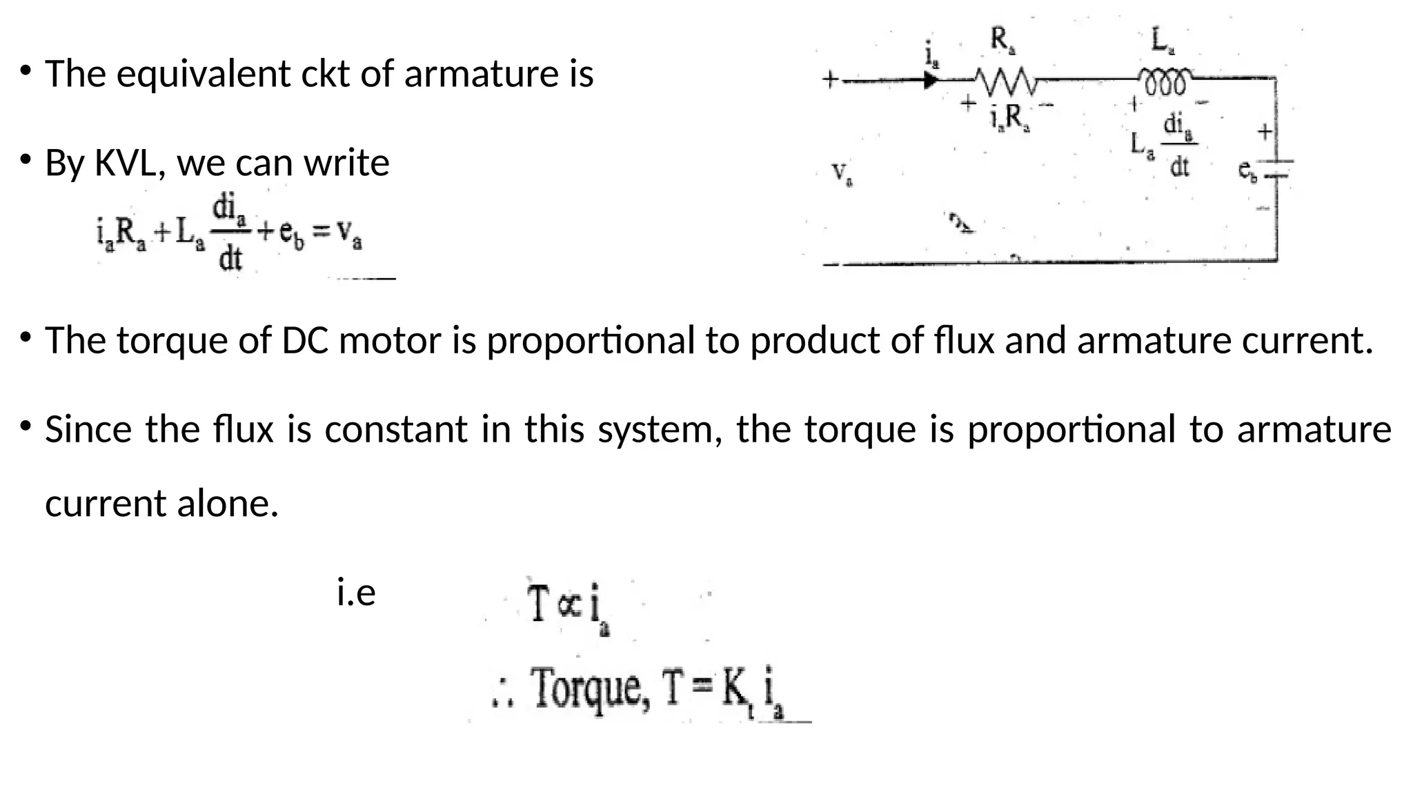
• The equivalentckt of armature is
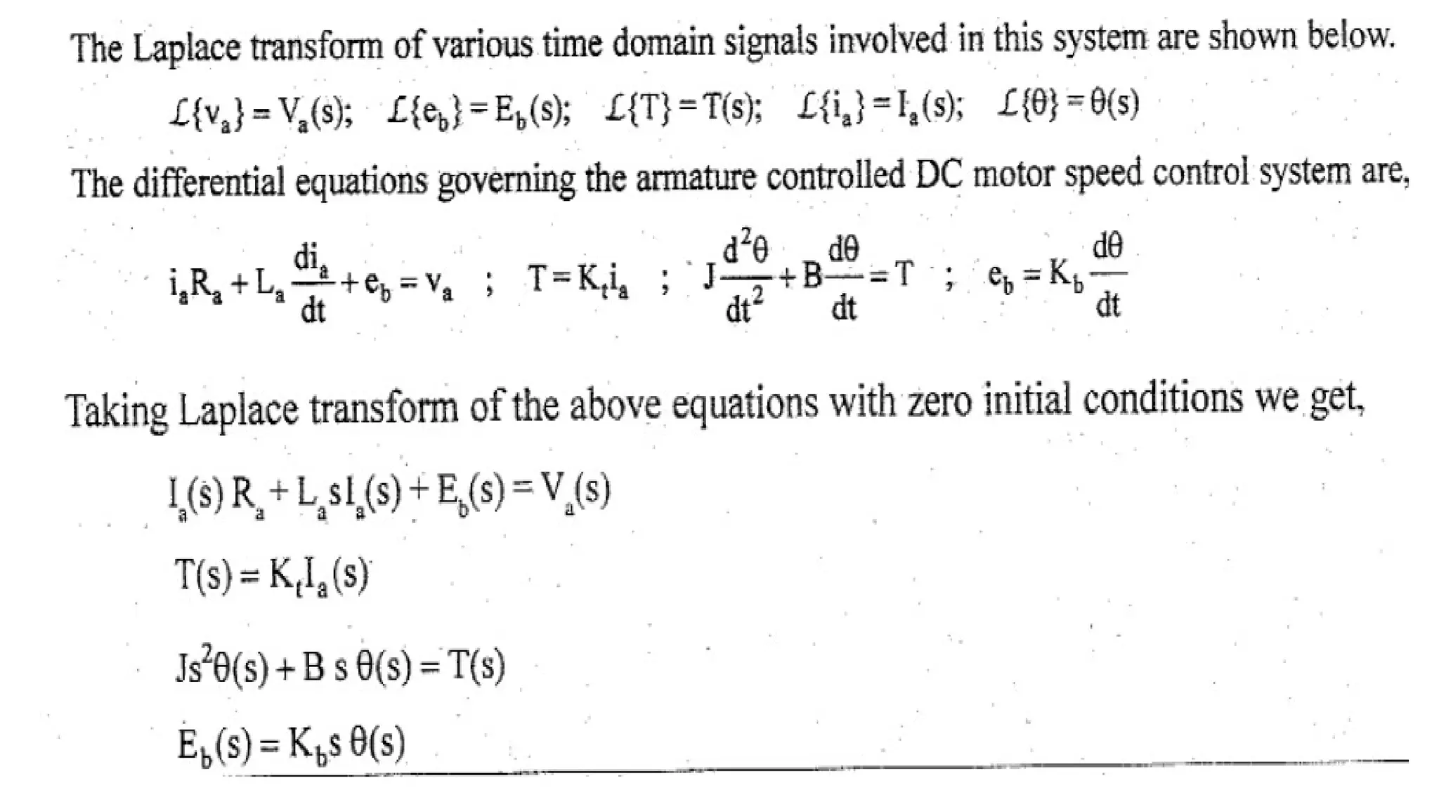
• By KVL, we can write
• The torque of DC motor is proportional to product of flux and armature current.
• Since the flux is constant in this system, the torque is proportional to armature
current alone.
i.e
11.
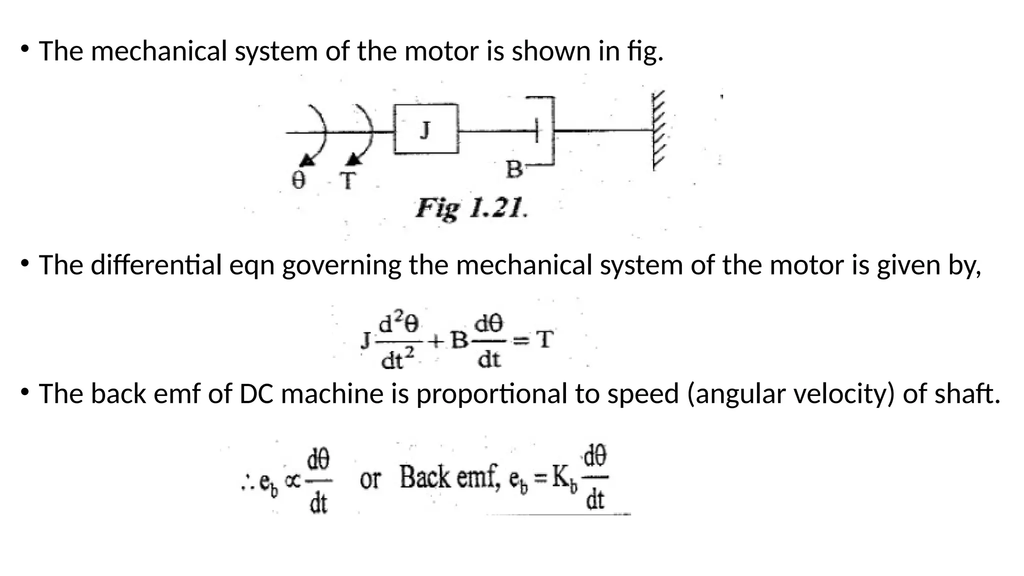
• The mechanicalsystem of the motor is shown in fig.
• The differential eqn governing the mechanical system of the motor is given by,
• The back emf of DC machine is proportional to speed (angular velocity) of shaft.
15.
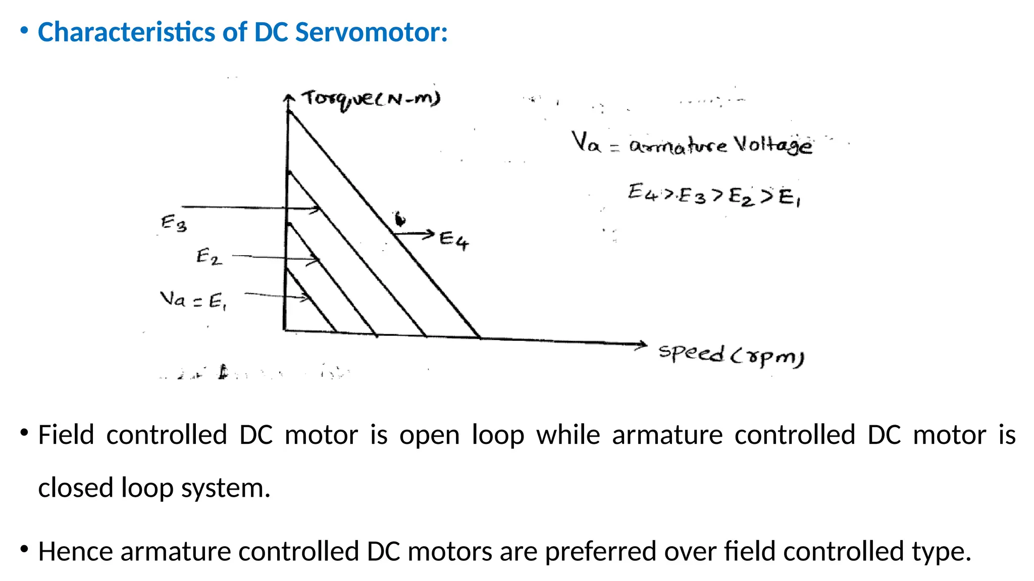
• Characteristics ofDC Servomotor:
• Field controlled DC motor is open loop while armature controlled DC motor is
closed loop system.
• Hence armature controlled DC motors are preferred over field controlled type.
16.
AC Servomotor
• Mostof the servomotors used in low power servomechanisms are AC
servomotors.
• The AC servomotor is basically a two-phase induction motor with some special
design features.
• The output of AC servomotor varies from fraction watts to few hundred watts.
• The operating frequency is 50Hz to 400Hz.
17.
Construction:
• It ismainly divided into two parts namely stator & rotor.
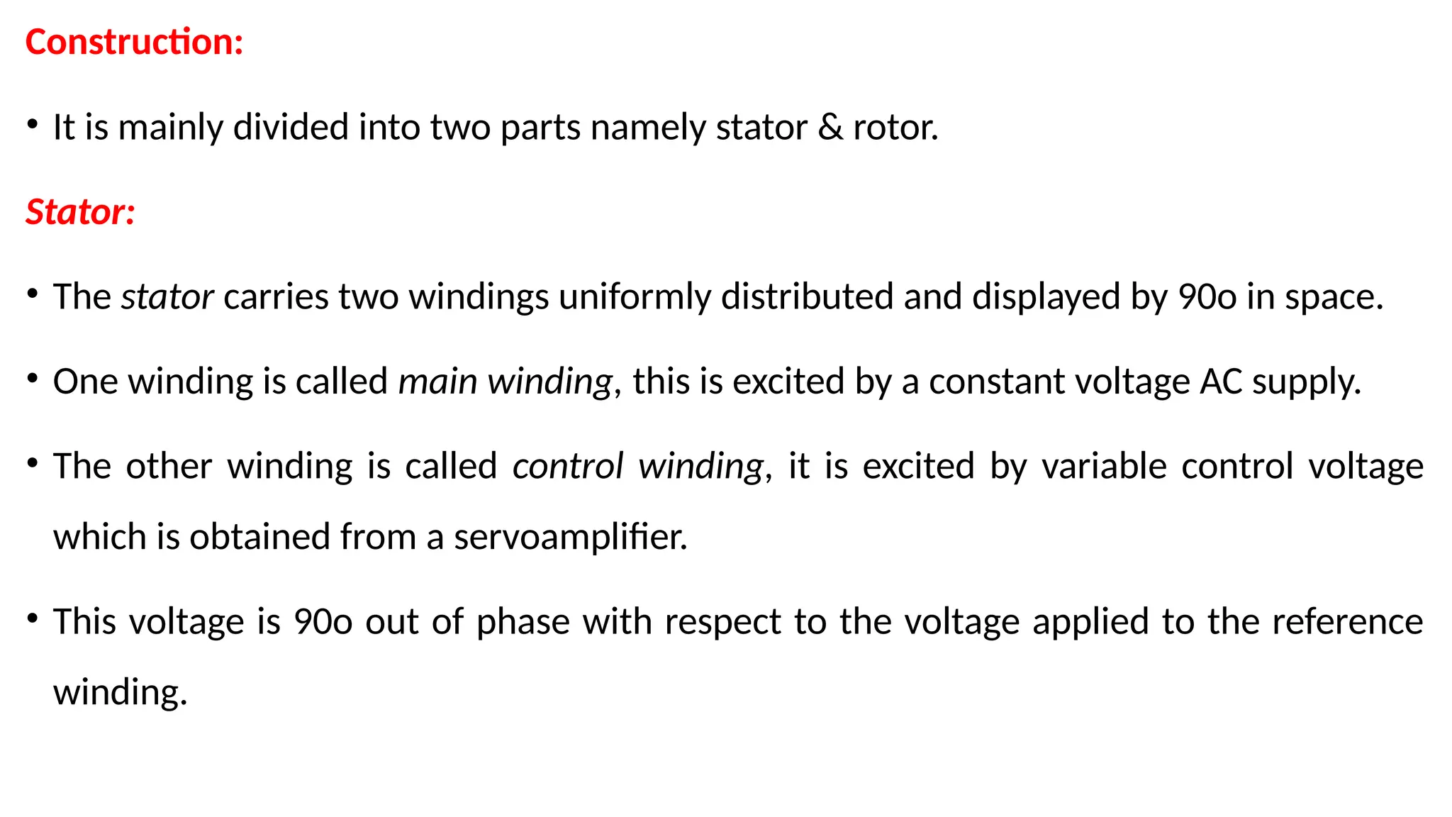
Stator:
• The stator carries two windings uniformly distributed and displayed by 90o in space.
• One winding is called main winding, this is excited by a constant voltage AC supply.
• The other winding is called control winding, it is excited by variable control voltage
which is obtained from a servoamplifier.
• This voltage is 90o out of phase with respect to the voltage applied to the reference
winding.
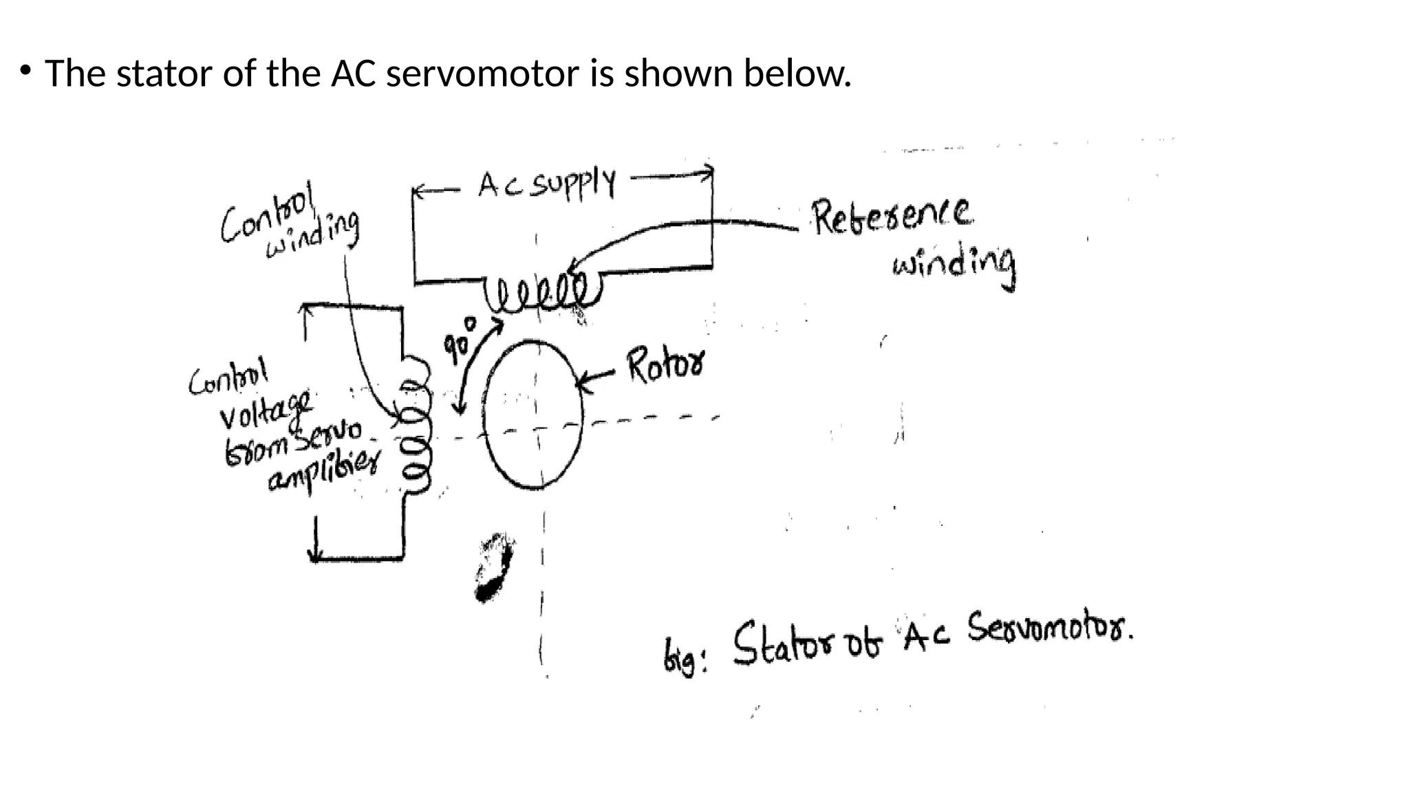
Rotor:
• The rotoris generally of two types. The one is usual
squirrel case rotor.
• This has small diameter & large length.
• Aluminium conductors are used to keep weight
small.
• Its resistance is very high to keep torque speed
characteristics as linear as possible.
• Air gap is kept very small which reduces
magnetising current.
• The case type rotor is shown with skewed bars in
the fig.
20.
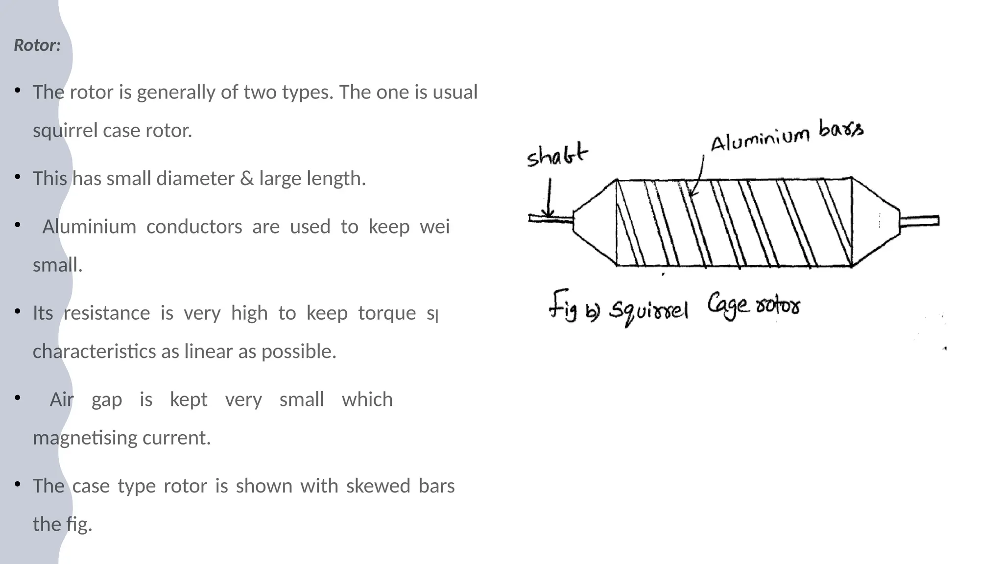
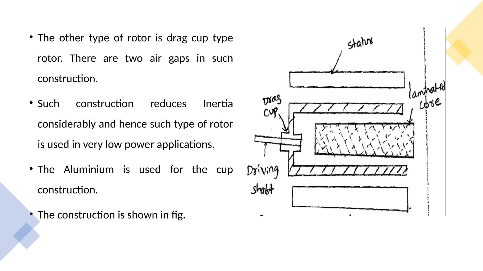
• The othertype of rotor is drag cup type
rotor. There are two air gaps in such
construction.
• Such construction reduces Inertia
considerably and hence such type of rotor
is used in very low power applications.
• The Aluminium is used for the cup
construction.
• The construction is shown in fig.
21.
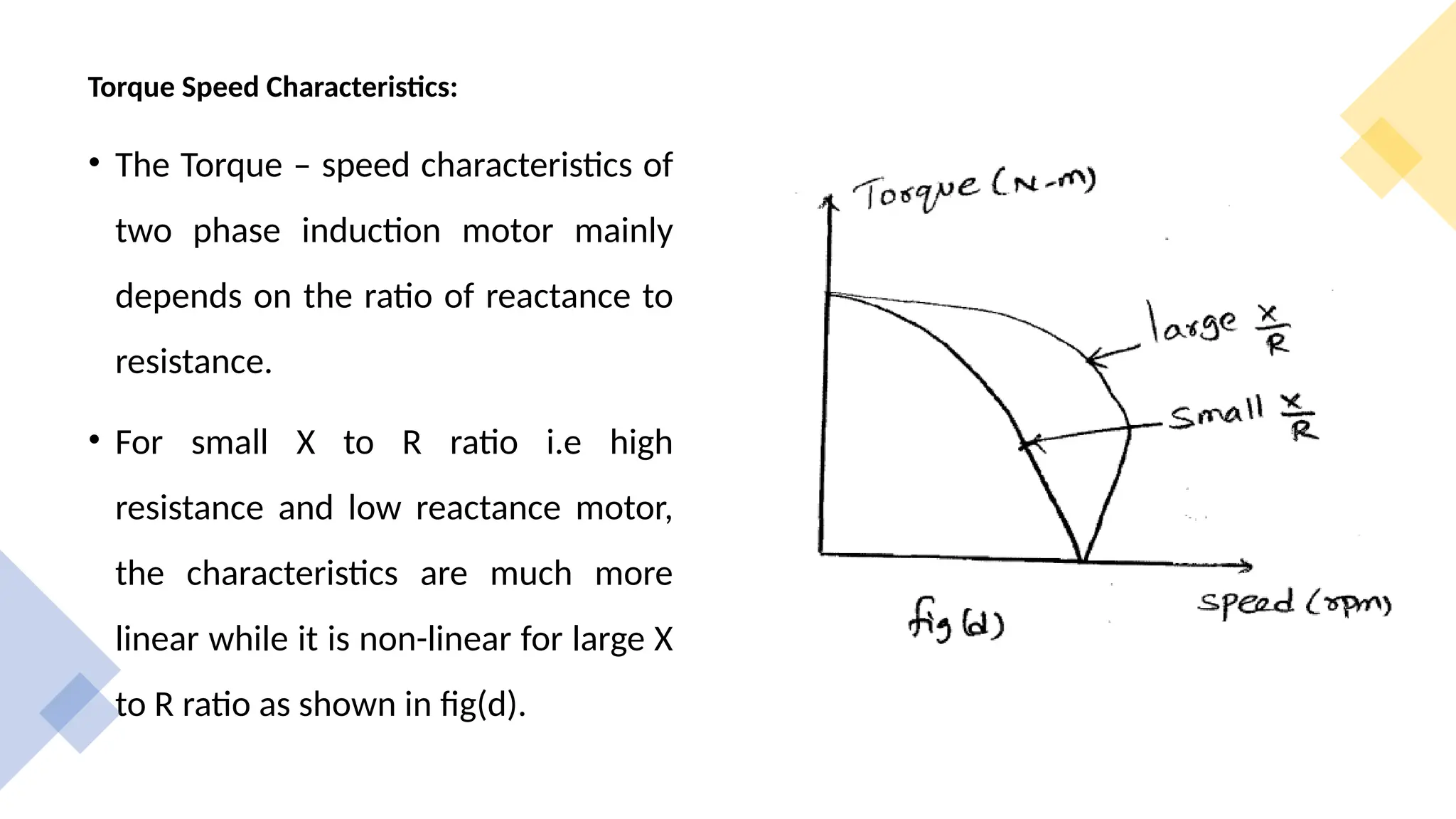
Torque Speed Characteristics:
•The Torque – speed characteristics of
two phase induction motor mainly
depends on the ratio of reactance to
resistance.
• For small X to R ratio i.e high
resistance and low reactance motor,
the characteristics are much more
linear while it is non-linear for large X
to R ratio as shown in fig(d).
22.
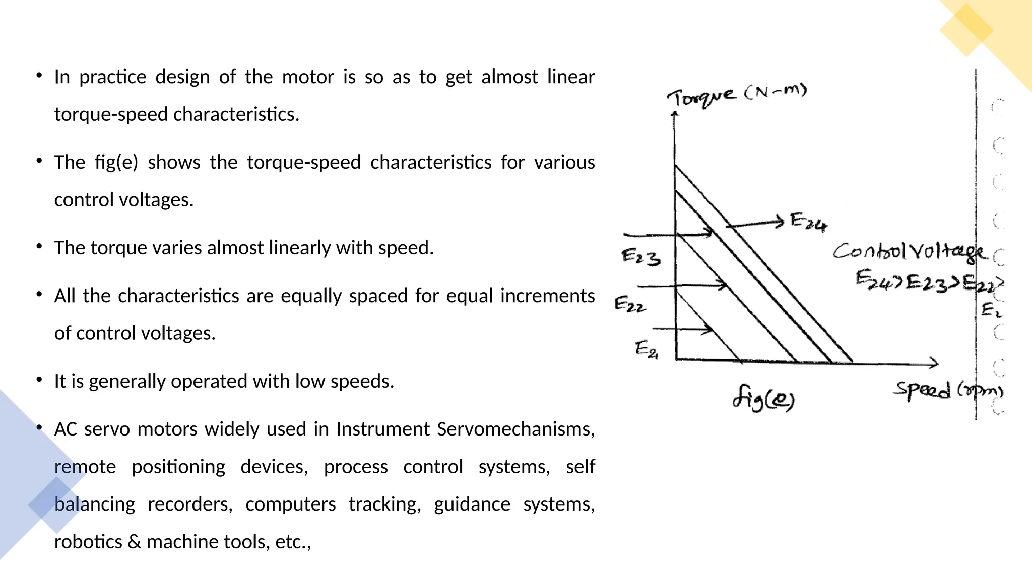
• In practicedesign of the motor is so as to get almost linear
torque-speed characteristics.
• The fig(e) shows the torque-speed characteristics for various
control voltages.
• The torque varies almost linearly with speed.
• All the characteristics are equally spaced for equal increments
of control voltages.
• It is generally operated with low speeds.
• AC servo motors widely used in Instrument Servomechanisms,
remote positioning devices, process control systems, self
balancing recorders, computers tracking, guidance systems,
robotics & machine tools, etc.,
23.
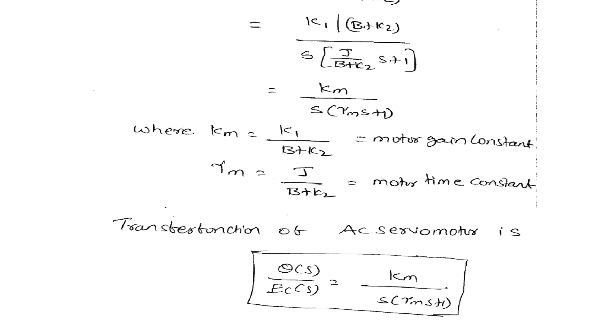
Transfer Function ofAC Servomotor
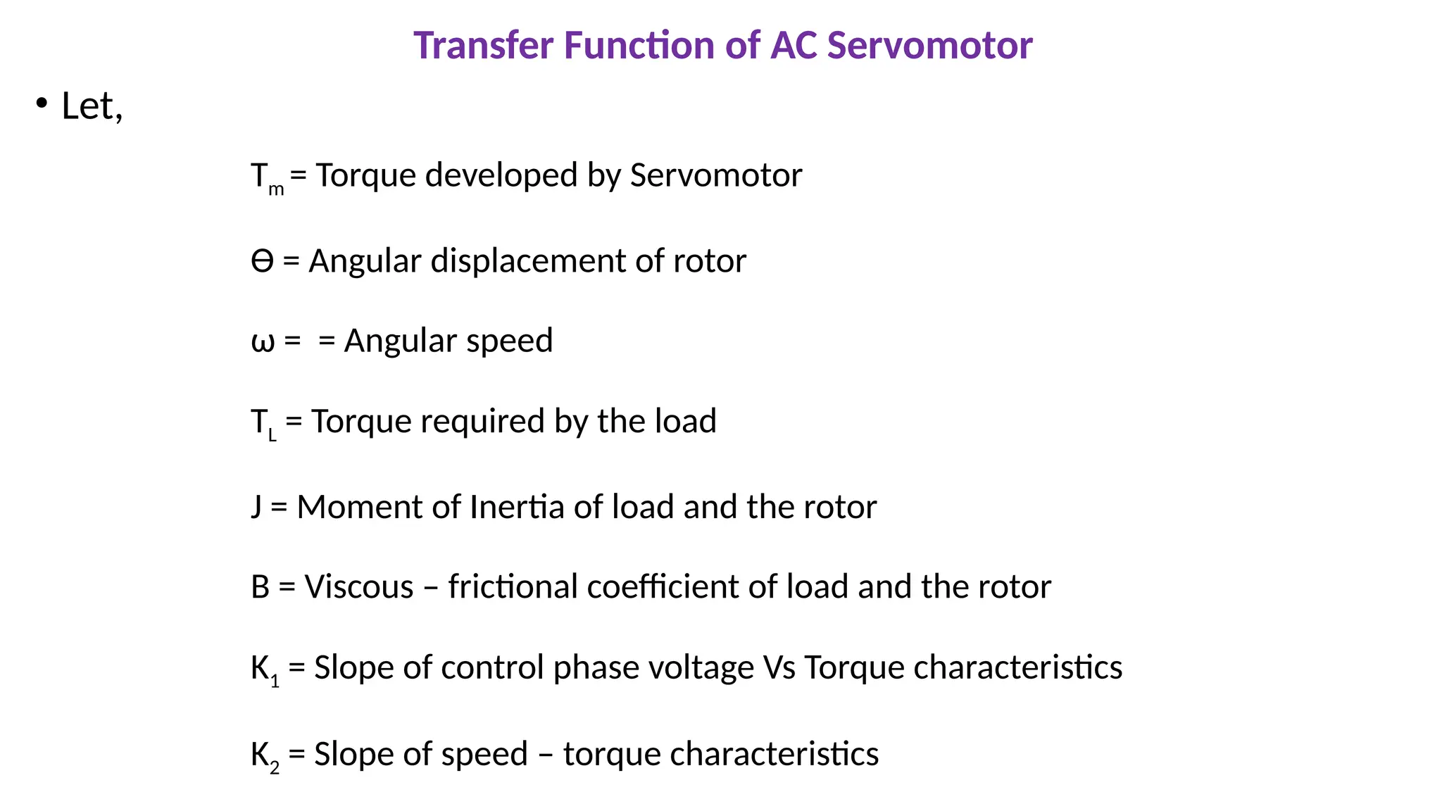
• Let,
Tm = Torque developed by Servomotor
Ɵ = Angular displacement of rotor
ω = = Angular speed
TL = Torque required by the load
J = Moment of Inertia of load and the rotor
B = Viscous – frictional coefficient of load and the rotor
K1 = Slope of control phase voltage Vs Torque characteristics
K2 = Slope of speed – torque characteristics
24.
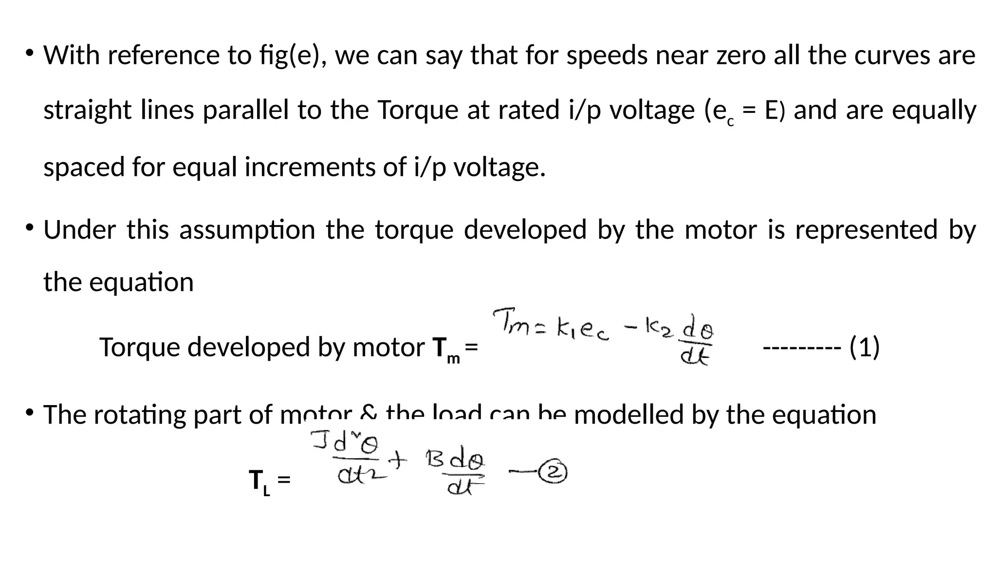
• With referenceto fig(e), we can say that for speeds near zero all the curves are
straight lines parallel to the Torque at rated i/p voltage (ec = E) and are equally
spaced for equal increments of i/p voltage.
• Under this assumption the torque developed by the motor is represented by
the equation
Torque developed by motor Tm = --------- (1)
• The rotating part of motor & the load can be modelled by the equation
TL =
25.
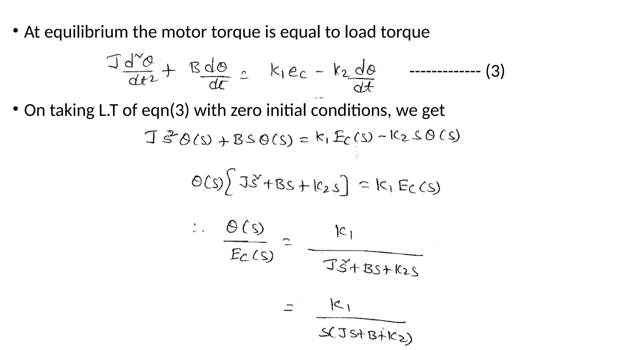
• At equilibriumthe motor torque is equal to load torque
------------- (3)
• On taking L.T of eqn(3) with zero initial conditions, we get
28.
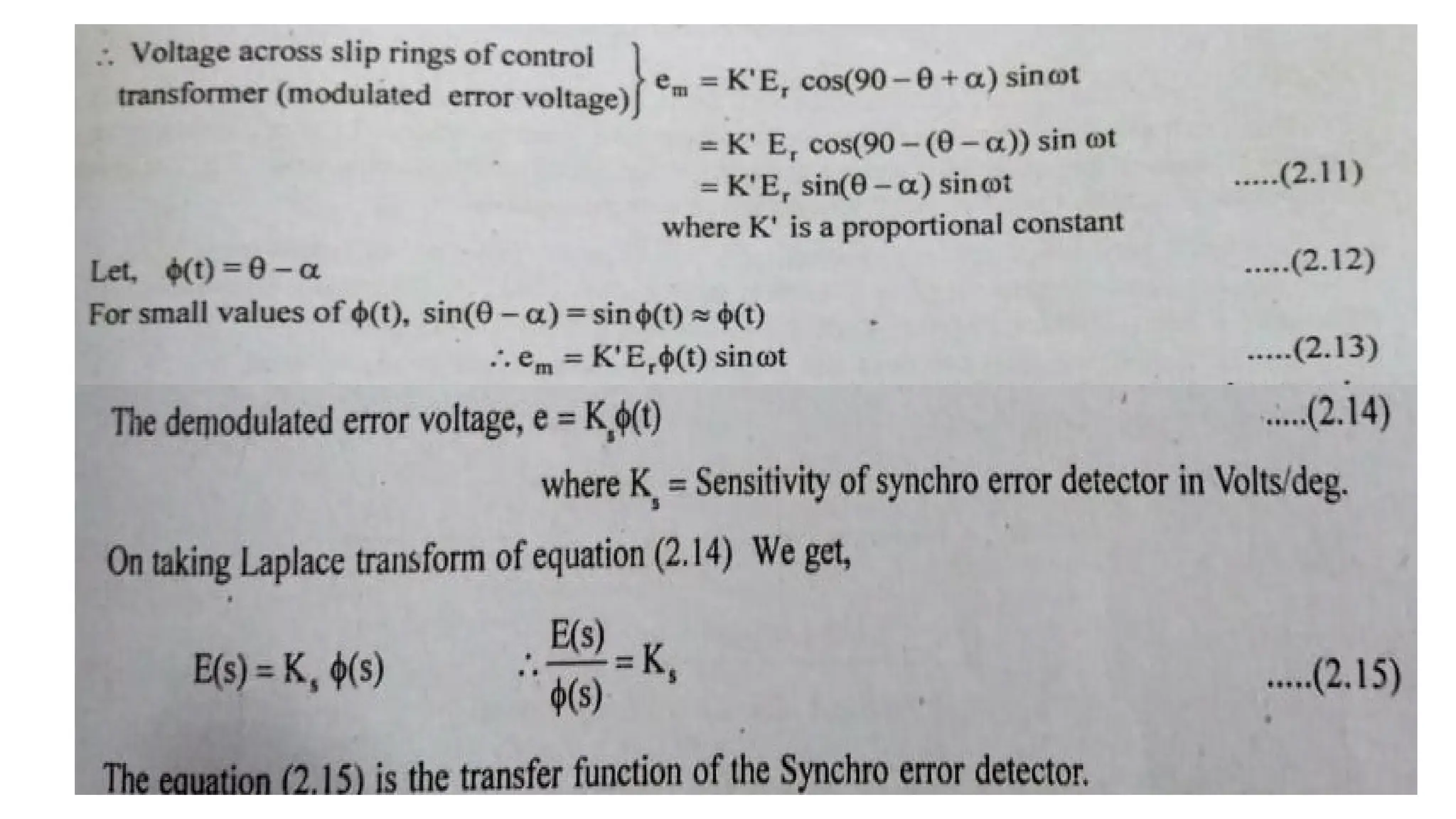
Synchro Transmitter andReceiver
SYNCHROS
• The term synchro is a generic name for a family of Inductive devices which
works on the principle of a rotating transformer (Induction Motor).
• A synchro is an electromagnetic transducer used to convert an angular position
of shaft into an electric signal. It is commercially known as selsyn or autosyn.
• It produces an output voltage depending upon angular position of the motor.
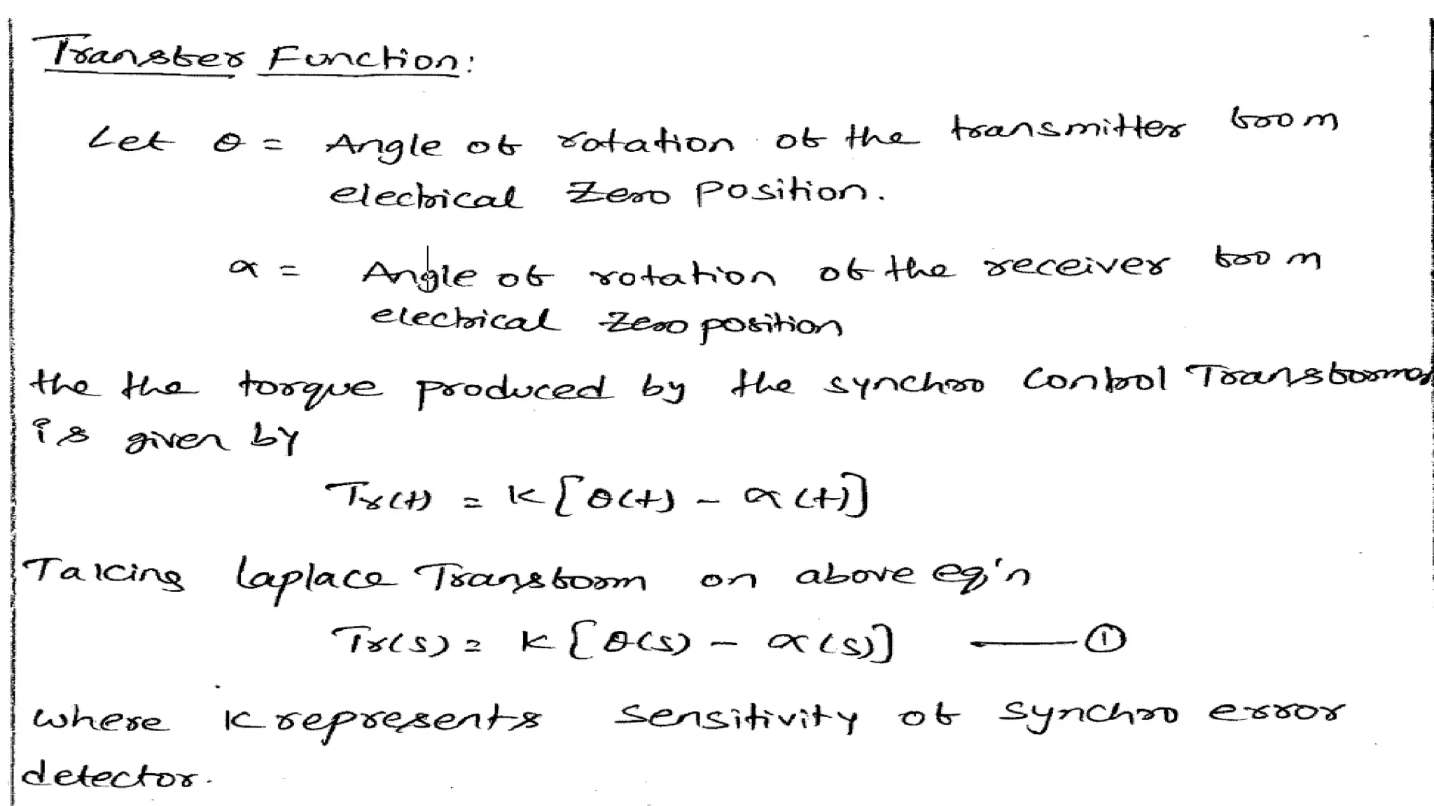
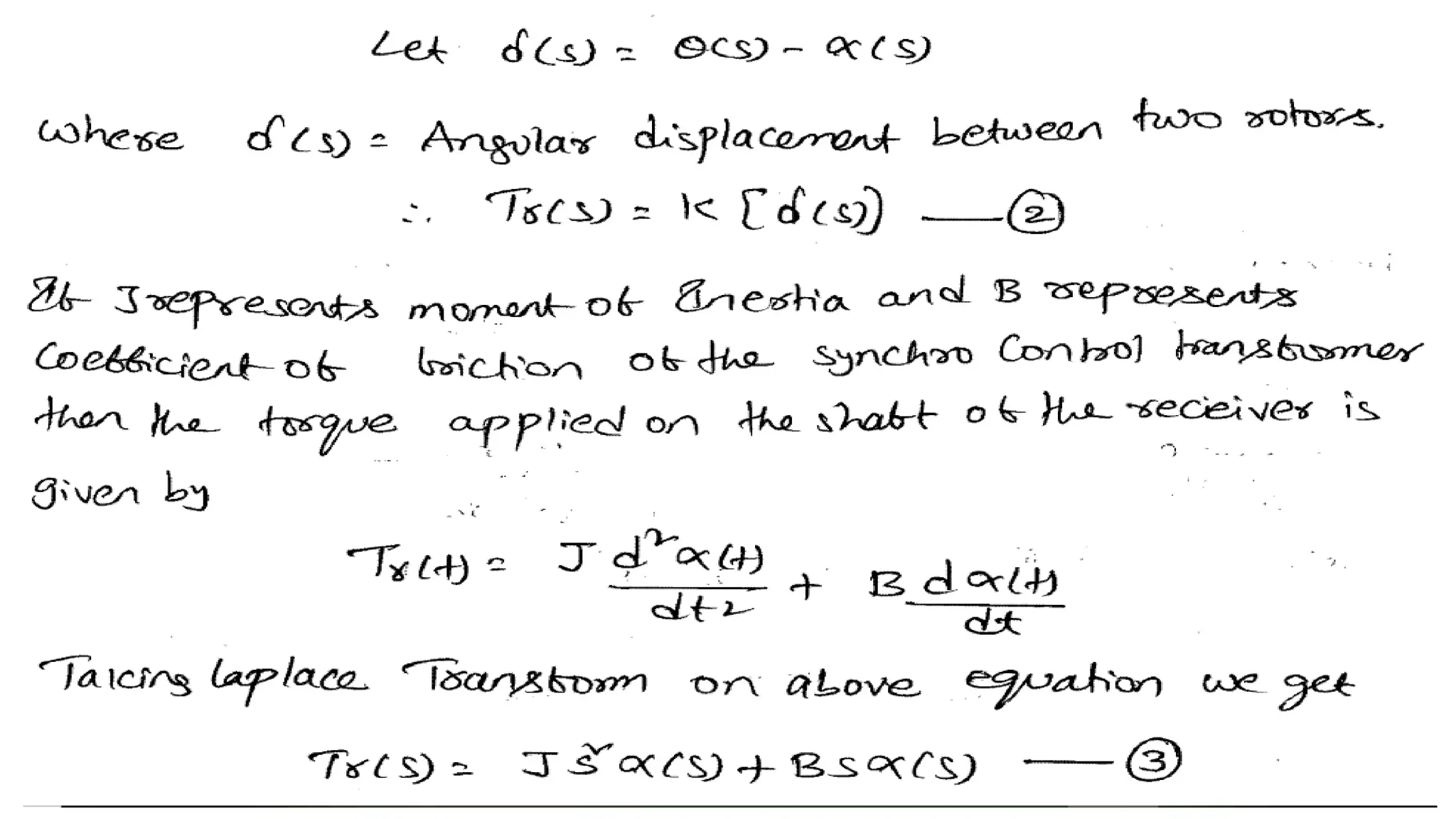
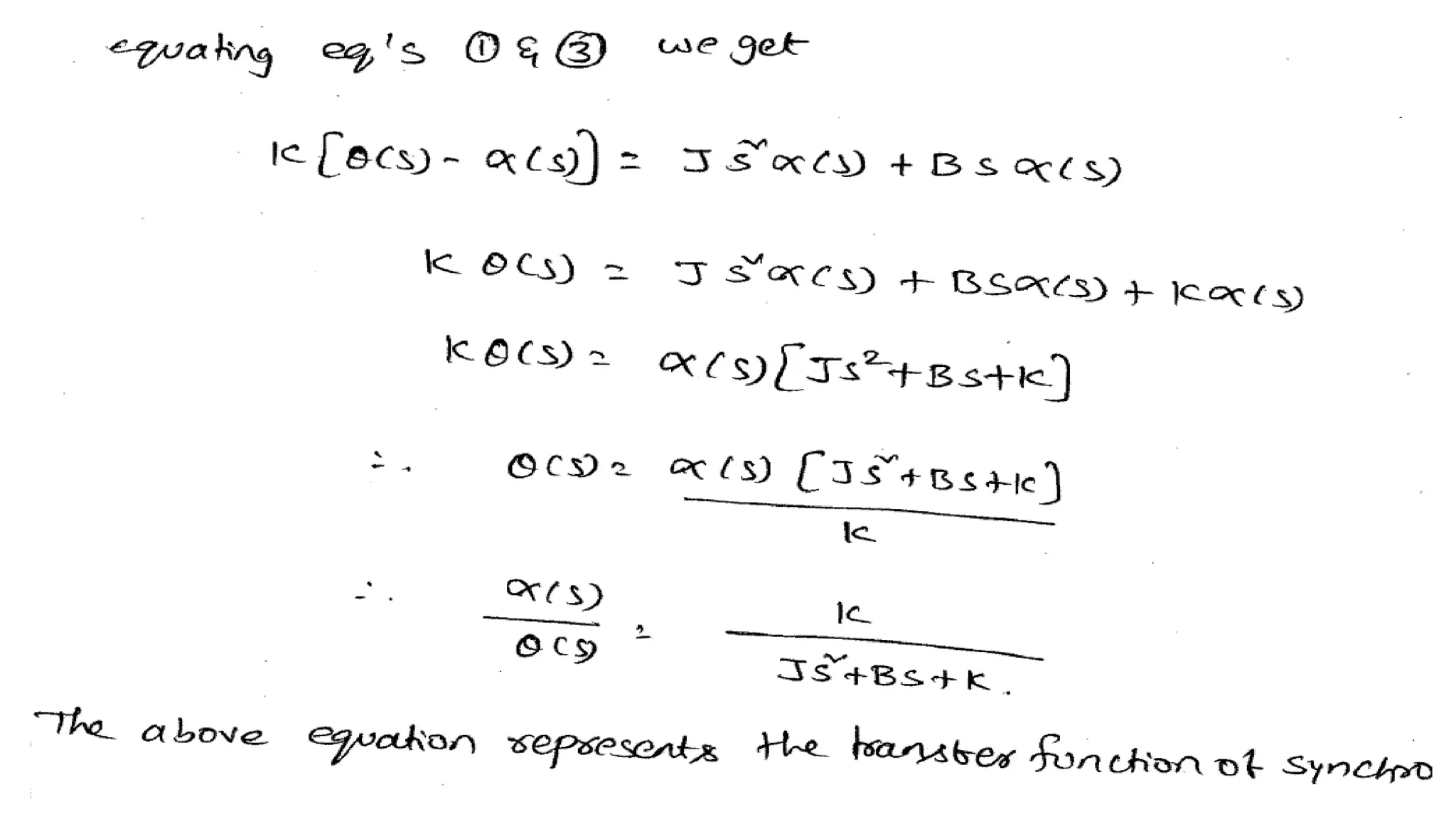
• A synchro system is formed by interconnection of the devices called the synchro
transmitter and the synchro control transformer.
29.
• They arealso called synchro pair.
• The synchro pair measures & compares two angular displacements and its
o/p voltage is approximately linear with angular difference of the axis of both
the shafts.
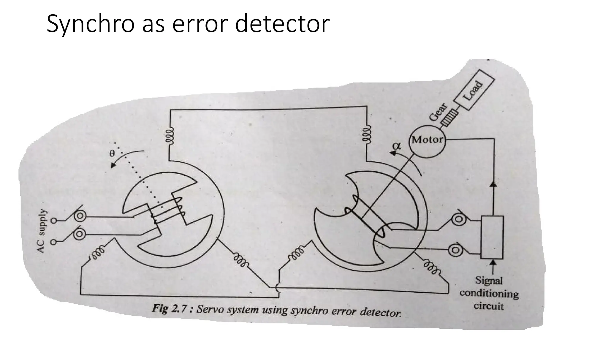
• They can be used in the following two ways.
1. To control the angular position of load from a remote place/ long distance.
2. For automatic correction of changes due to disturbance in the angular
position of the load.
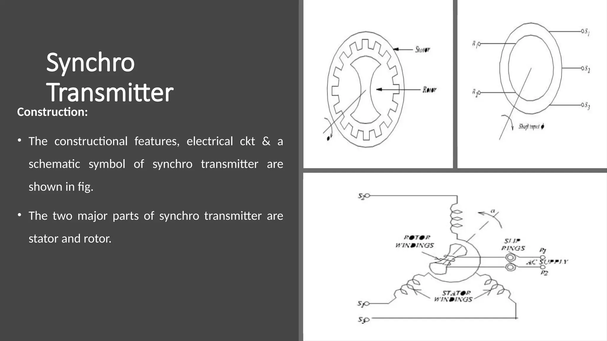
• The statoris made up of laminated silicon steel and slotted on the inner
periphery to accommodate a balanced 3-phase winding.
• The stator winding is concentric type with the axis of 3 coils 120o
apart. The
stator winding is star connected i.e Y-connection.
• The rotor is of dumb bell construction with a single winding.
• The ends of rotor winding are terminated on two slip rings.
• A single phase ac excitation voltage is applied to rotor through slip rings.
32.
Working Principle:
• Whenthe rotor is excited by ac voltage, the rotor current flows , and a magnetic field is produced.
• The rotor magnetic field induces an emf in the stator coils by transformer action.
• The effective voltage induced in any stator coil depends upon the angular position of the coil’s axis
w.r.t rotor axis.
Let, er = Instantaneous value of AC voltage applied to rotor.
es1,es2, es3 = Instantaneous value of emf induced in stator coils S1, S2, S3 w.r.t neutral respectively.
Er = Maximum value of rotor excitation voltage.
ω = Angular frequency of rotor excitation voltage.
Kt = Turns ratio of stator and rotor winding.
Kc = Coupling coefficient.
Ɵ = Angular displacement of rotor w.r.t reference.
33.
Let, The instantaneousvalue of excitation voltage, er = Er Sinωt
• Let the rotor rotates in anticlockwise direction. When the rotor rotates by an angle Ɵ, emfs
are induced in stator coils.
• The frequency of induced emf is same as that of rotor frequency.
• The magnitude of induced emfs are proportional to the turns ratio and coupling coefficient.
• The turns ratio, Kt is a constant, but coupling coefficient, Kc is a function of rotor angular
position.
Therefore, Induced emf in stator coil = Kt Kc Er sin ωt ---------(1)
34.
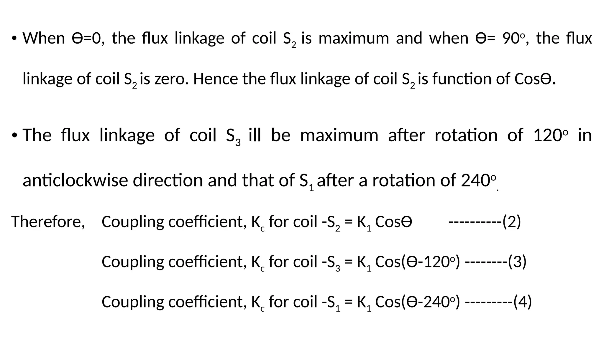
• When Ɵ=0,the flux linkage of coil S2 is maximum and when Ɵ= 90o
, the flux
linkage of coil S2 is zero. Hence the flux linkage of coil S2 is function of CosƟ.
• The flux linkage of coil S3 ill be maximum after rotation of 120o
in
anticlockwise direction and that of S1 after a rotation of 240o
.
Therefore, Coupling coefficient, Kc for coil -S2 = K1 CosƟ ----------(2)
Coupling coefficient, Kc for coil -S3 = K1 Cos(Ɵ-120o
) --------(3)
Coupling coefficient, Kc for coil -S1 = K1 Cos(Ɵ-240o
) ---------(4)
35.
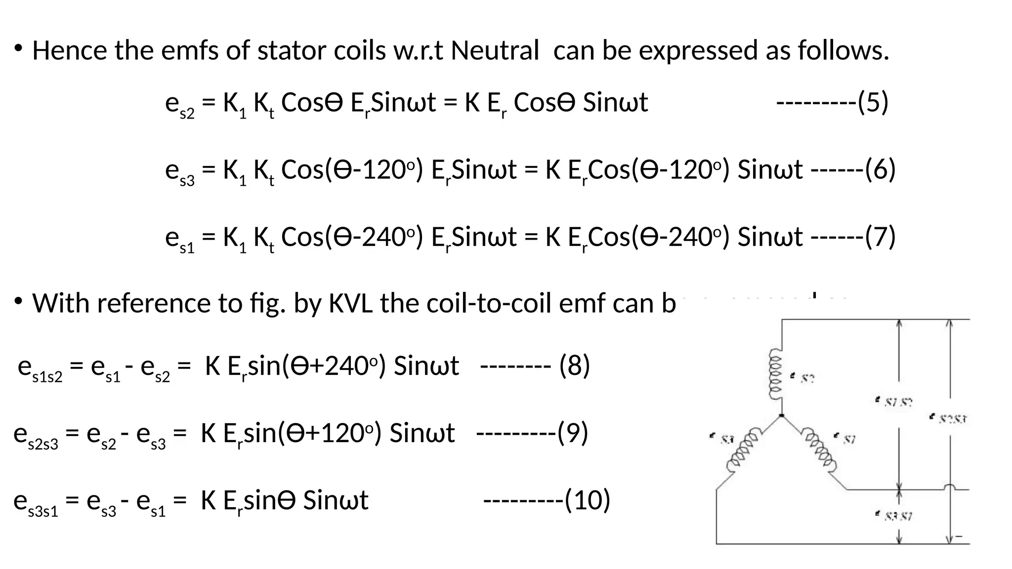
• Hence theemfs of stator coils w.r.t Neutral can be expressed as follows.
es2 = K1 Kt CosƟ ErSinωt = K Er CosƟ Sinωt ---------(5)
es3 = K1 Kt Cos(Ɵ-120o
) ErSinωt = K ErCos(Ɵ-120o
) Sinωt ------(6)
es1 = K1 Kt Cos(Ɵ-240o
) ErSinωt = K ErCos(Ɵ-240o
) Sinωt ------(7)
• With reference to fig. by KVL the coil-to-coil emf can be expressed as
es1s2 = es1 - es2 = K Ersin(Ɵ+240o
) Sinωt -------- (8)
es2s3 = es2 - es3 = K Ersin(Ɵ+120o
) Sinωt ---------(9)
es3s1 = es3 - es1 = K ErsinƟ Sinωt ---------(10)
36.
• When Ɵ=0,from eqn5 we can say that maximum emf is induced in coil S2.
• But from eqn10 it is observed that th ecoil-to-coil voltage es3s1 is zero.
• This position of the rotor is defined as the electrical zero of the transmitter.
• The electrical zero position is used as reference for specifying the angular position of rotor.
• The i/p to syncho transmitter is the angular position of its rotor shaft and the o/p is a set
of 3 stator coil-to-coil voltages.
• By measuring & identifying the set of voltages at the stator terminals, it is to identify the
angular position of the rotor.
• A device called synchro/digital converter is available to measure the stator voltages & to
calculate the angular measure and then display the direction & angle of rotation.
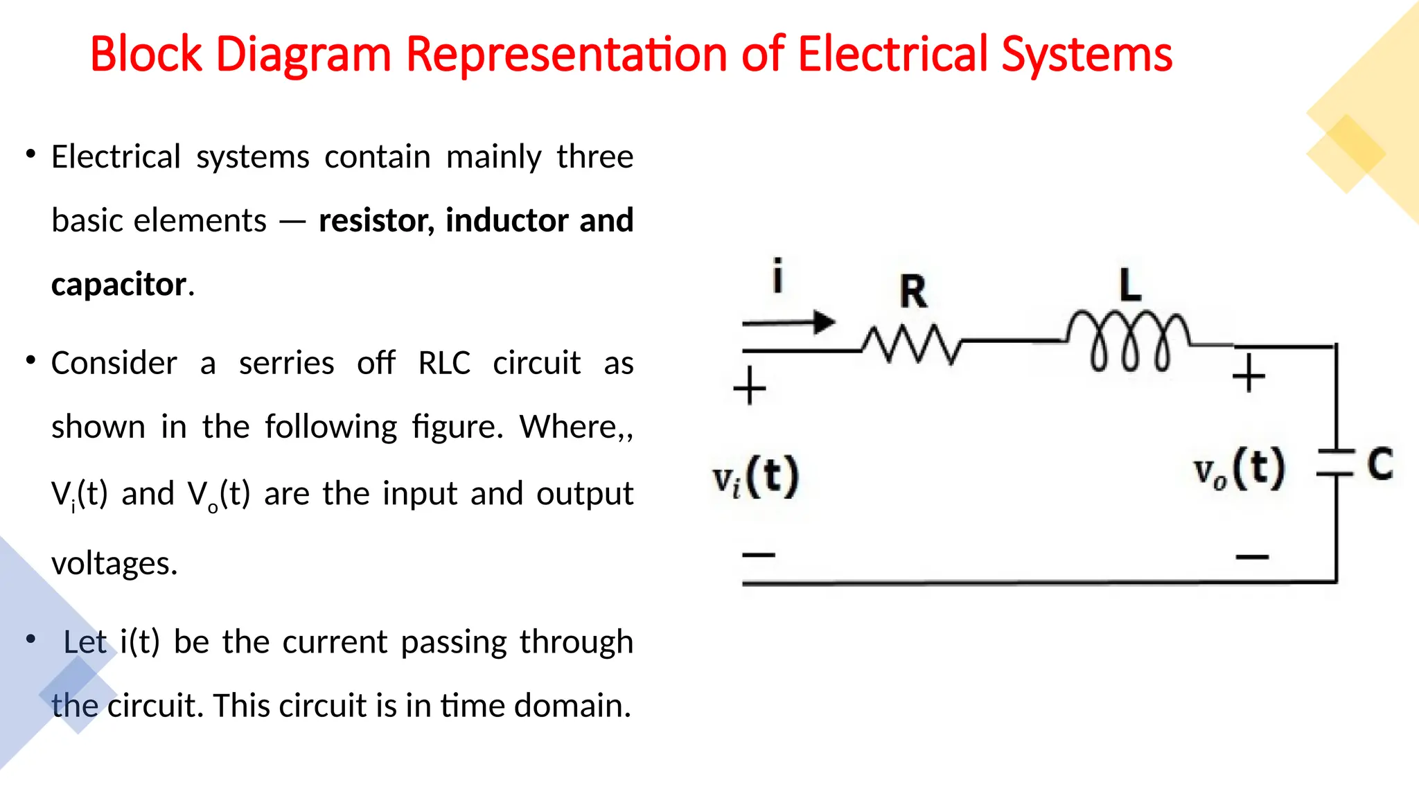
Block Diagram Representationof Electrical Systems
• Electrical systems contain mainly three
basic elements — resistor, inductor and
capacitor.
• Consider a serries off RLC circuit as
shown in the following figure. Where,,
Vi(t) and Vo(t) are the input and output
voltages.
• Let i(t) be the current passing through
the circuit. This circuit is in time domain.
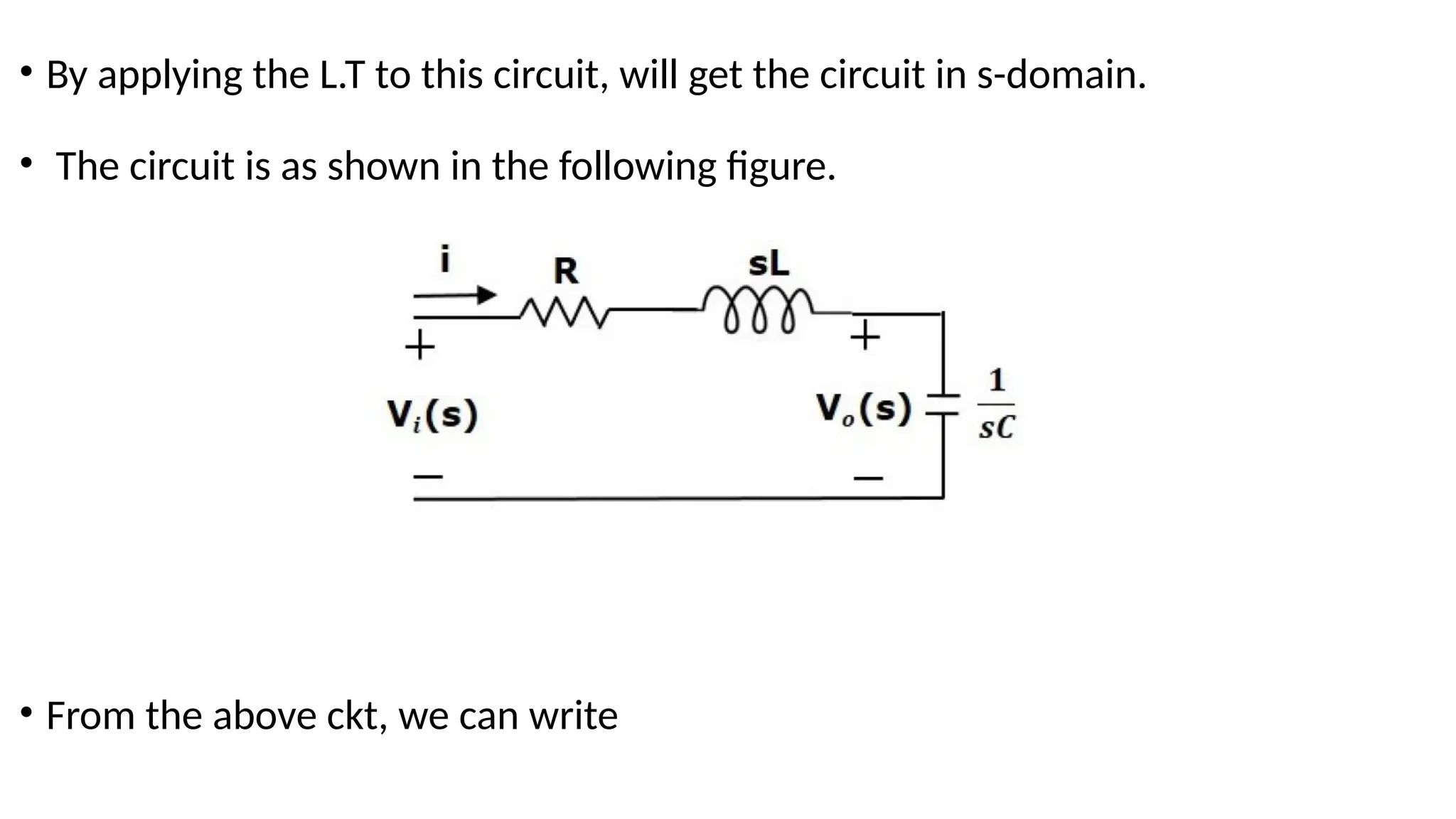
44.
• By applyingthe L.T to this circuit, will get the circuit in s-domain.
• The circuit is as shown in the following figure.
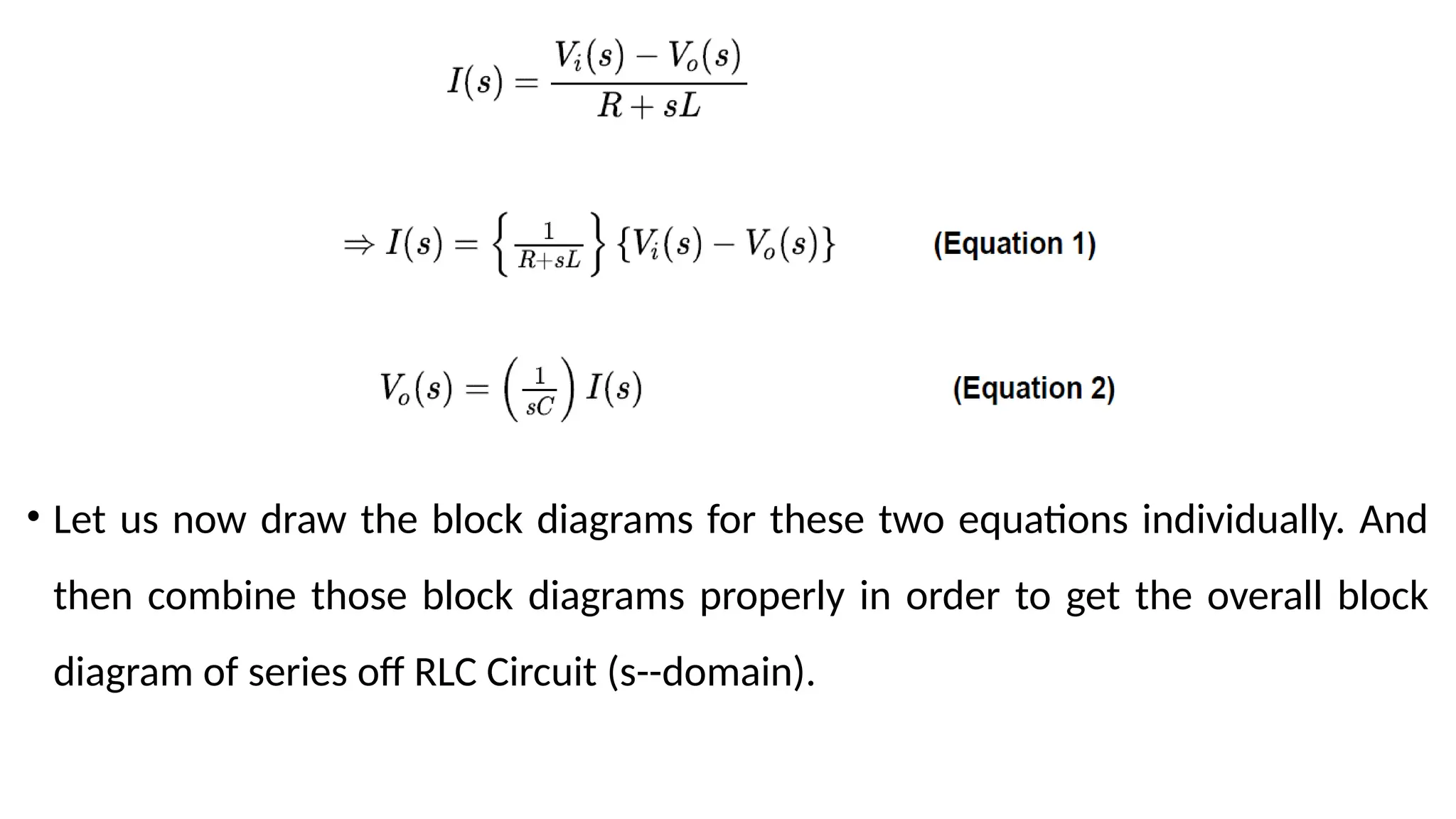
• From the above ckt, we can write
45.
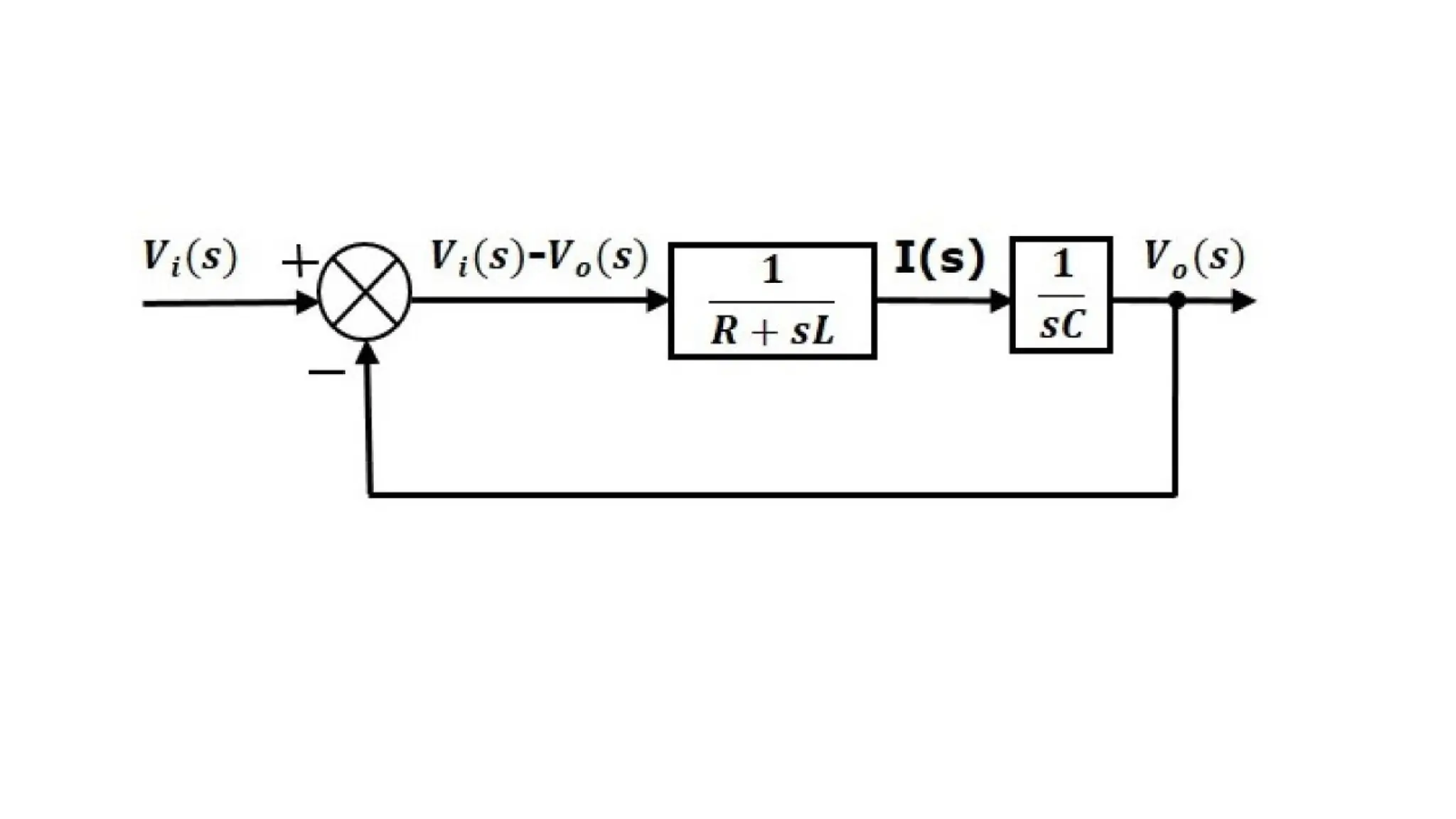
• Let usnow draw the block diagrams for these two equations individually. And
then combine those block diagrams properly in order to get the overall block
diagram of series off RLC Circuit (s--domain).
46.
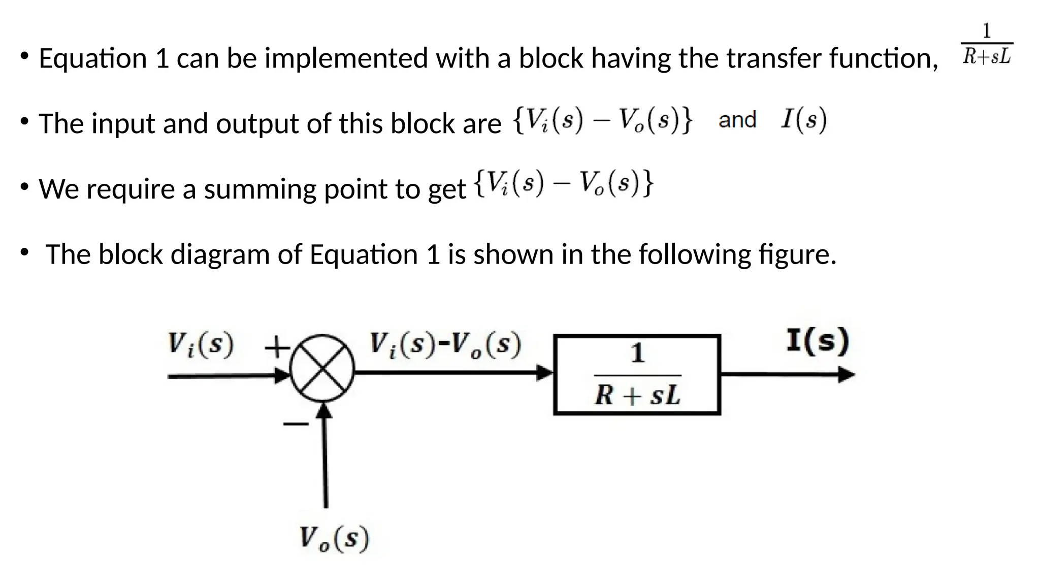
• Equation 1can be implemented with a block having the transfer function,
• The input and output of this block are
• We require a summing point to get
• The block diagram of Equation 1 is shown in the following figure.
47.
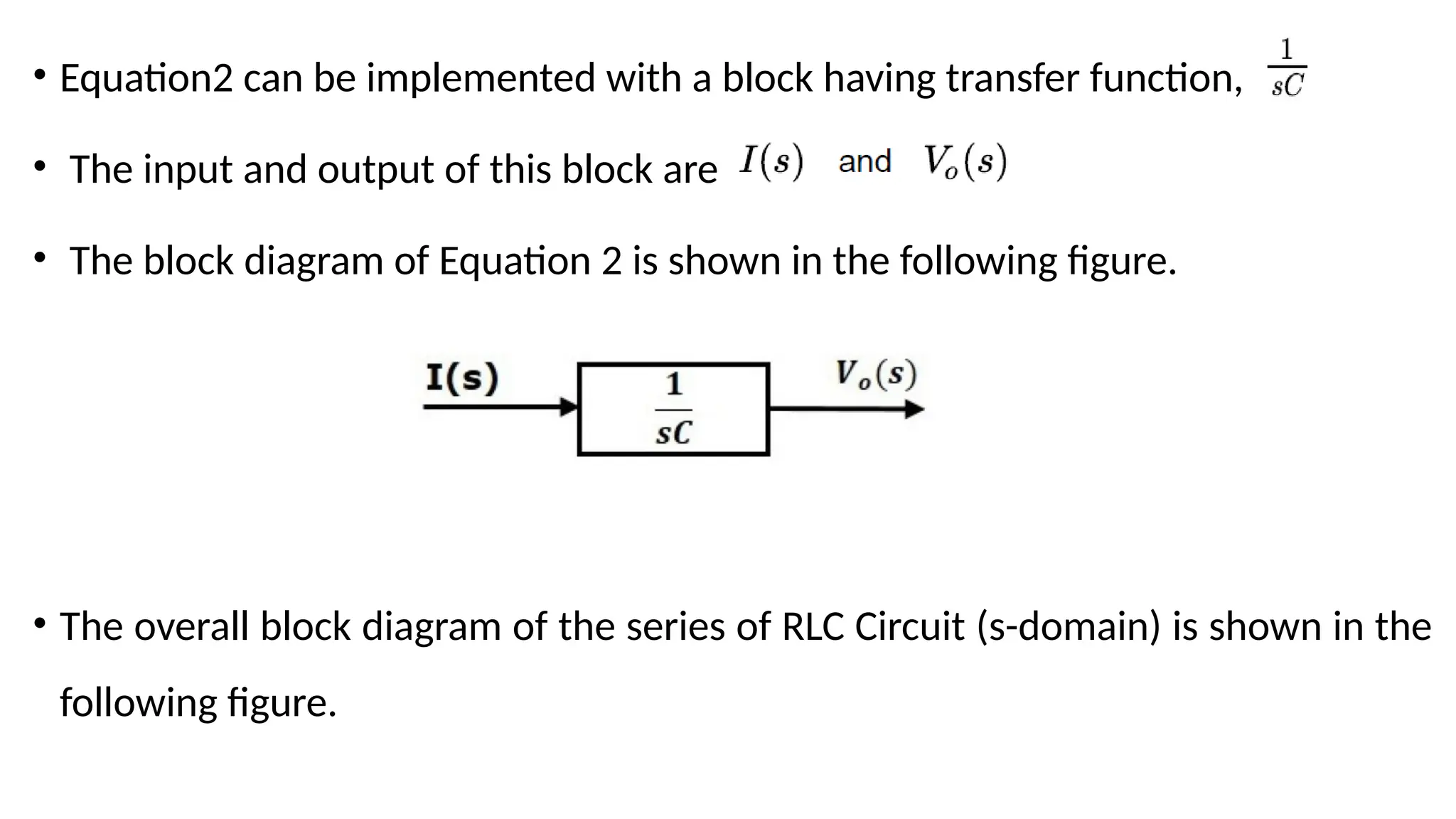
• Equation2 canbe implemented with a block having transfer function,
• The input and output of this block are
• The block diagram of Equation 2 is shown in the following figure.
• The overall block diagram of the series of RLC Circuit (s-domain) is shown in the
following figure.
49.
• Similarly,, youcan draw the block diagram of any electrical circuit or system just
by following this simple procedure.
• Convert the time domain electrical circuit into an s-domain electrical circuit by
applying L.T.
• Write down the equations for the current passing through allll series branch
elements and voltage across all shunt branches.
• Draw the block diagrams for all the above equations individually.
• Combine all these block diagrams properly in order to get the overall block
diagram of the electrical circuit (s-domain).
50.
Block Diagram Algebra
•A Block Diagram of a system is a pictorial representation of the functions
performed by each component and of the flow of signals.
• A control system may consists of three elements for its block diagram.
• They are
1. Block
2. Branch Point
3. Summing Point
51.
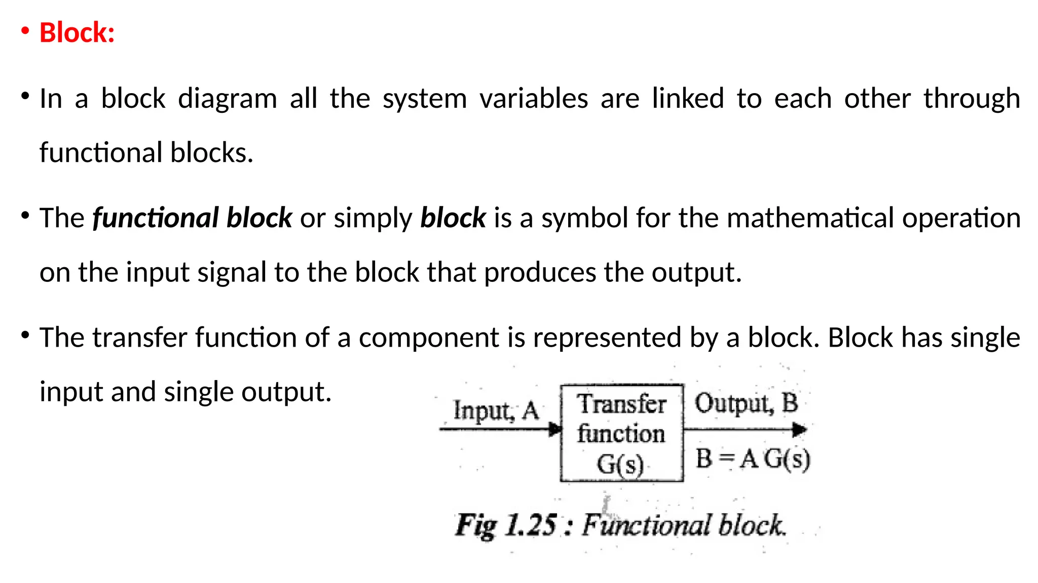
• Block:
• Ina block diagram all the system variables are linked to each other through
functional blocks.
• The functional block or simply block is a symbol for the mathematical operation
on the input signal to the block that produces the output.
• The transfer function of a component is represented by a block. Block has single
input and single output.
52.
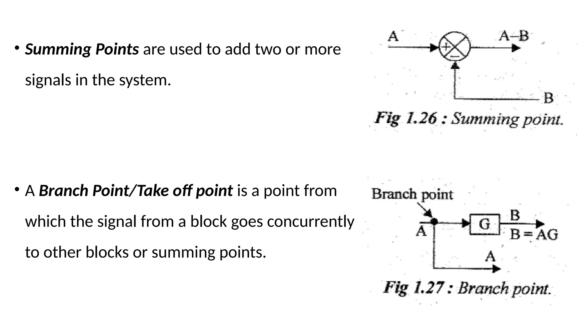
• Summing Pointsare used to add two or more
signals in the system.
• A Branch Point/Take off point is a point from
which the signal from a block goes concurrently
to other blocks or summing points.
53.
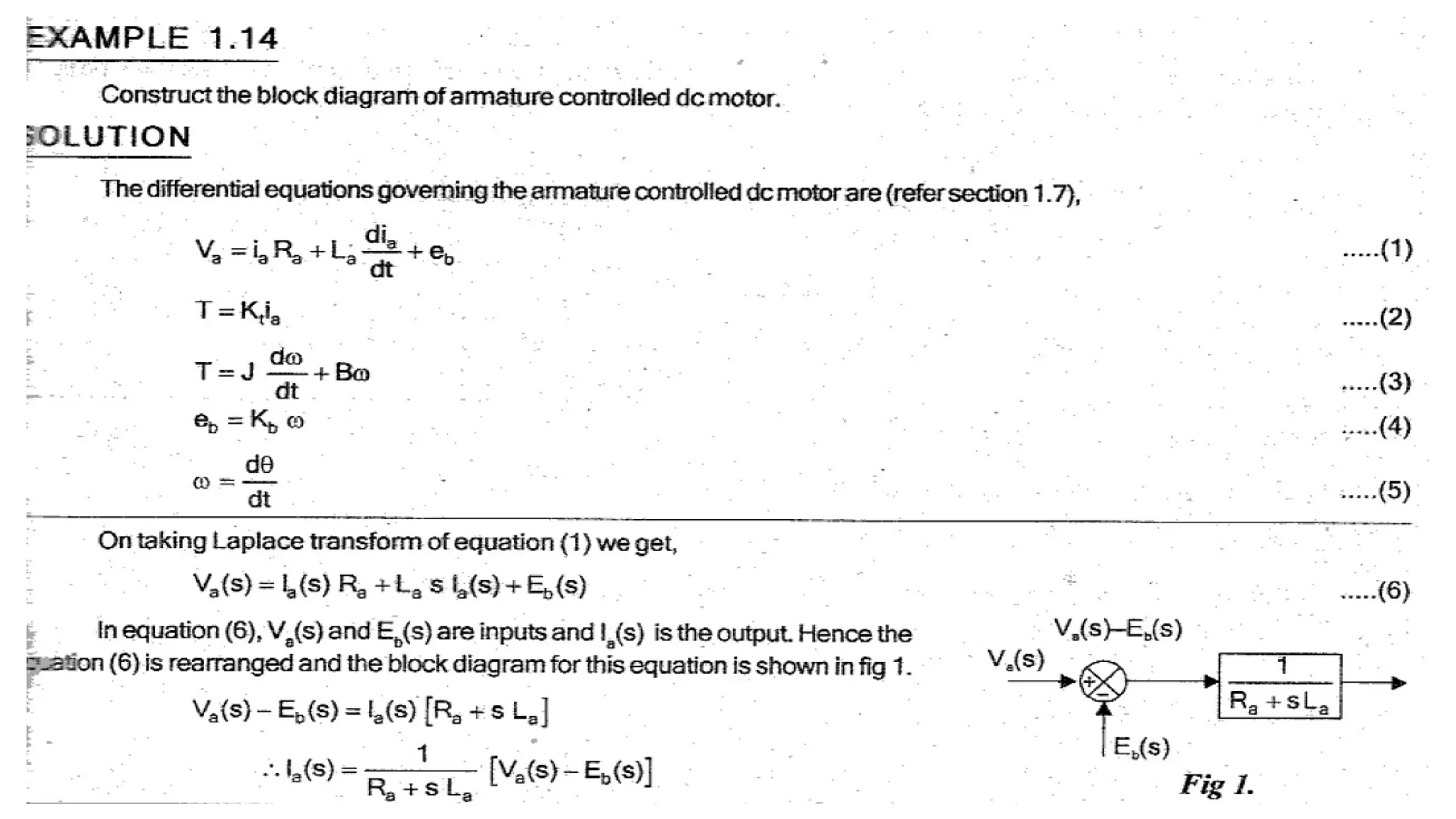
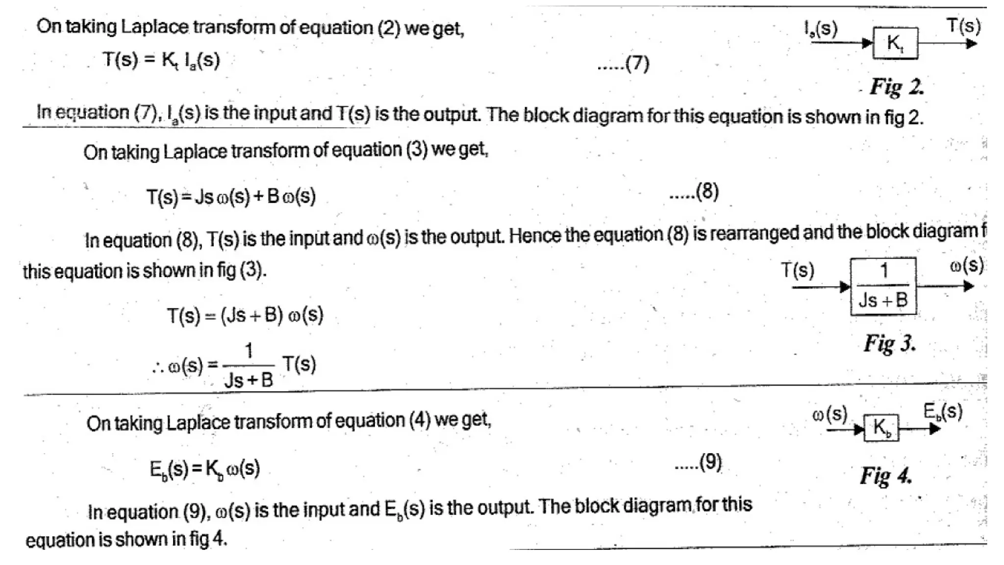
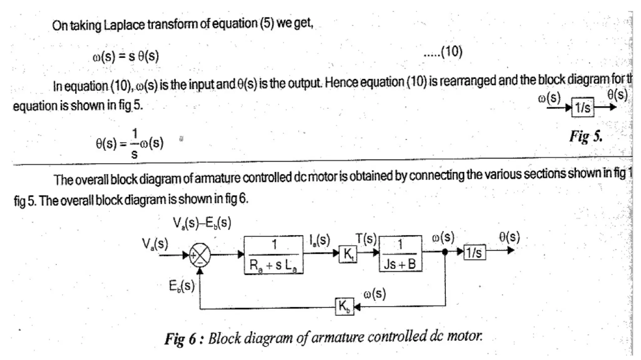
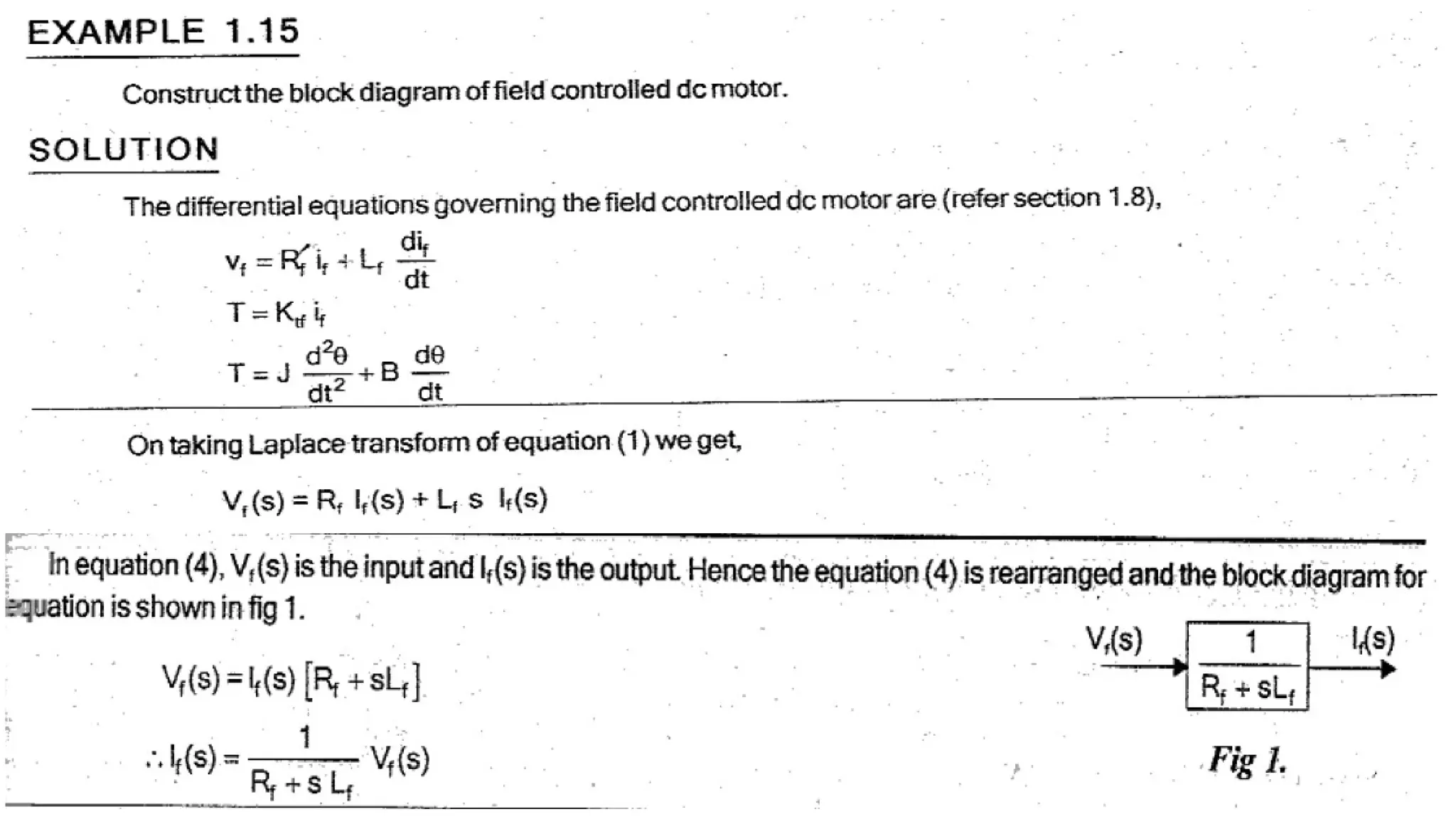
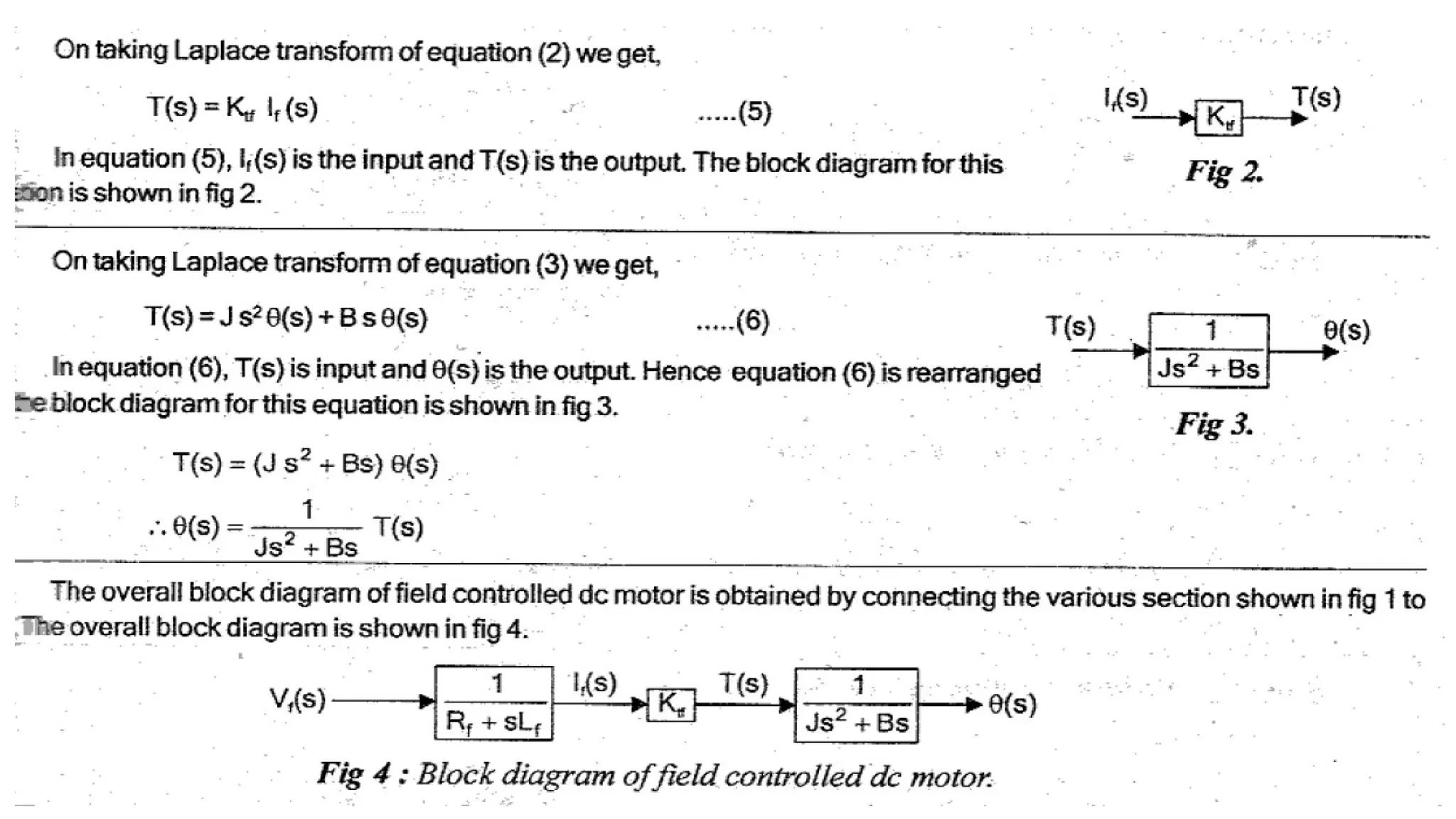
Constructing Block Diagramfor Control Systems
• A control system can be represented diagrammatically by block diagram.
• The Diff.Eqns governing the system are used to construct the block diagram.
• By taking L.T the D.Eqns are converted to algebraic eqns. The eqns will have variables &
constants.
• From the working knowledge of the system the i/p and o/p variables are identified and
the block diagram for each eqn can be drawn.
• Each eqn gives one section of block diagram. The o/p of one section will be i/p to the other
section.
• The various sections are interconneced to obtain the overall block diagram of the system.
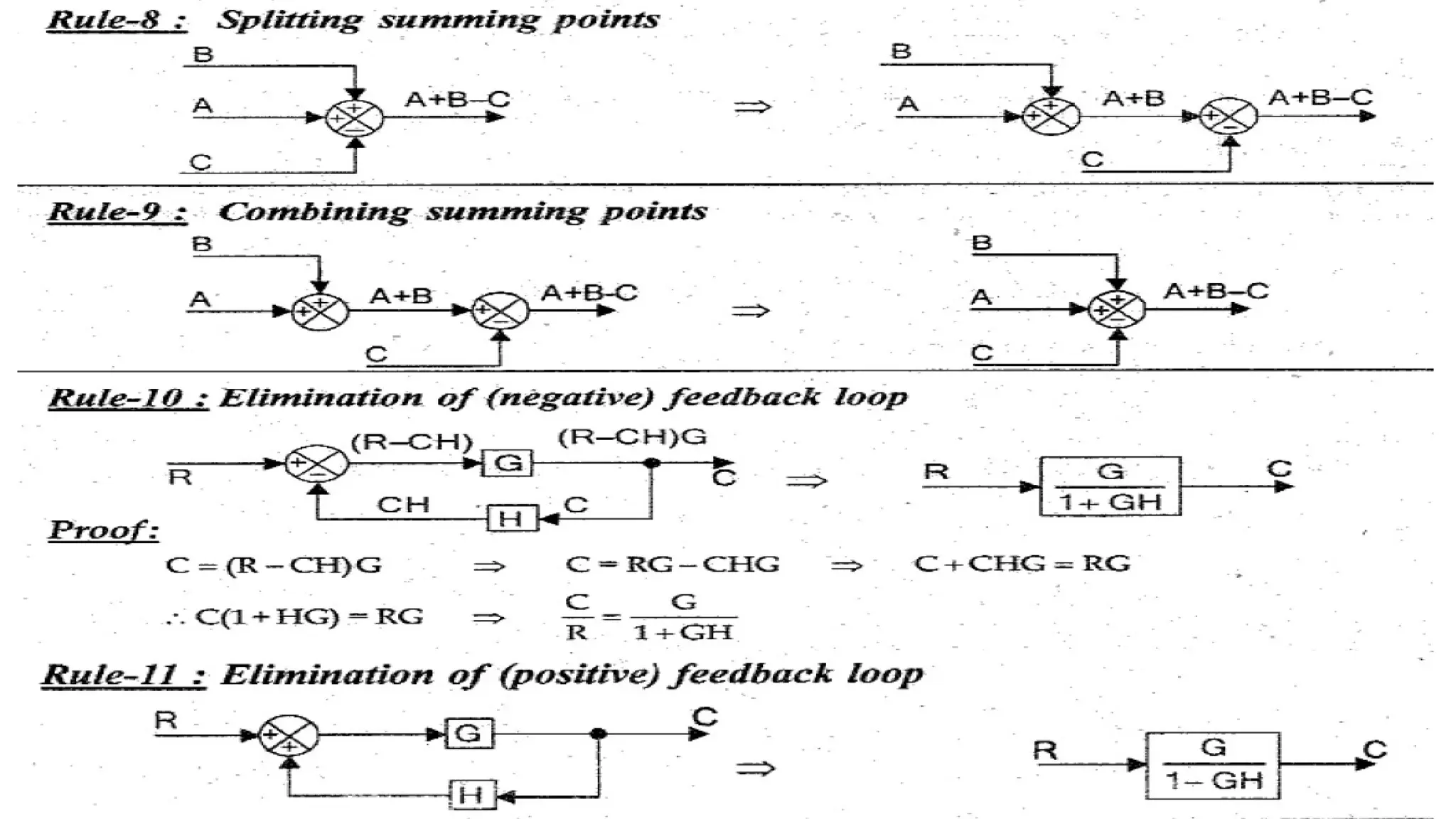
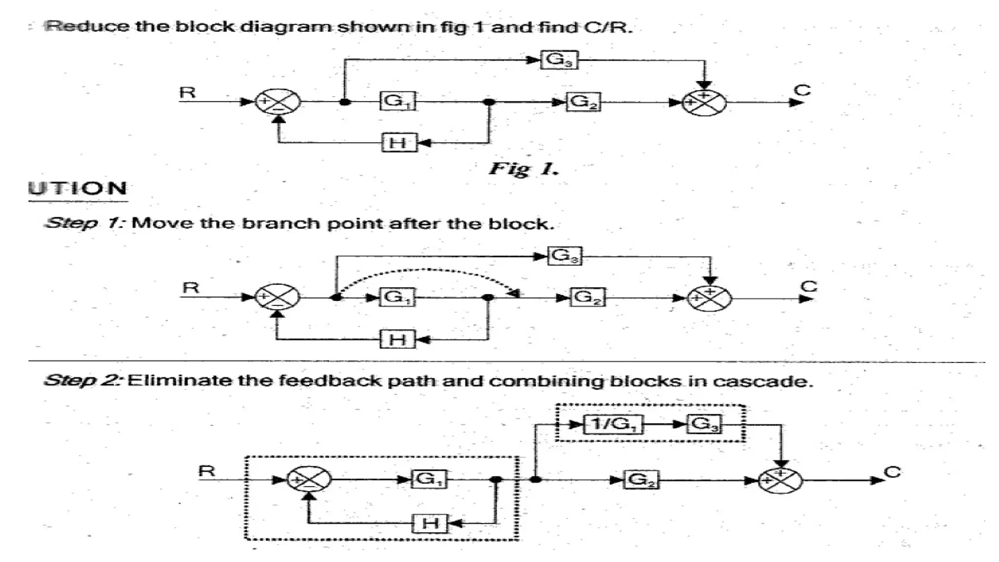
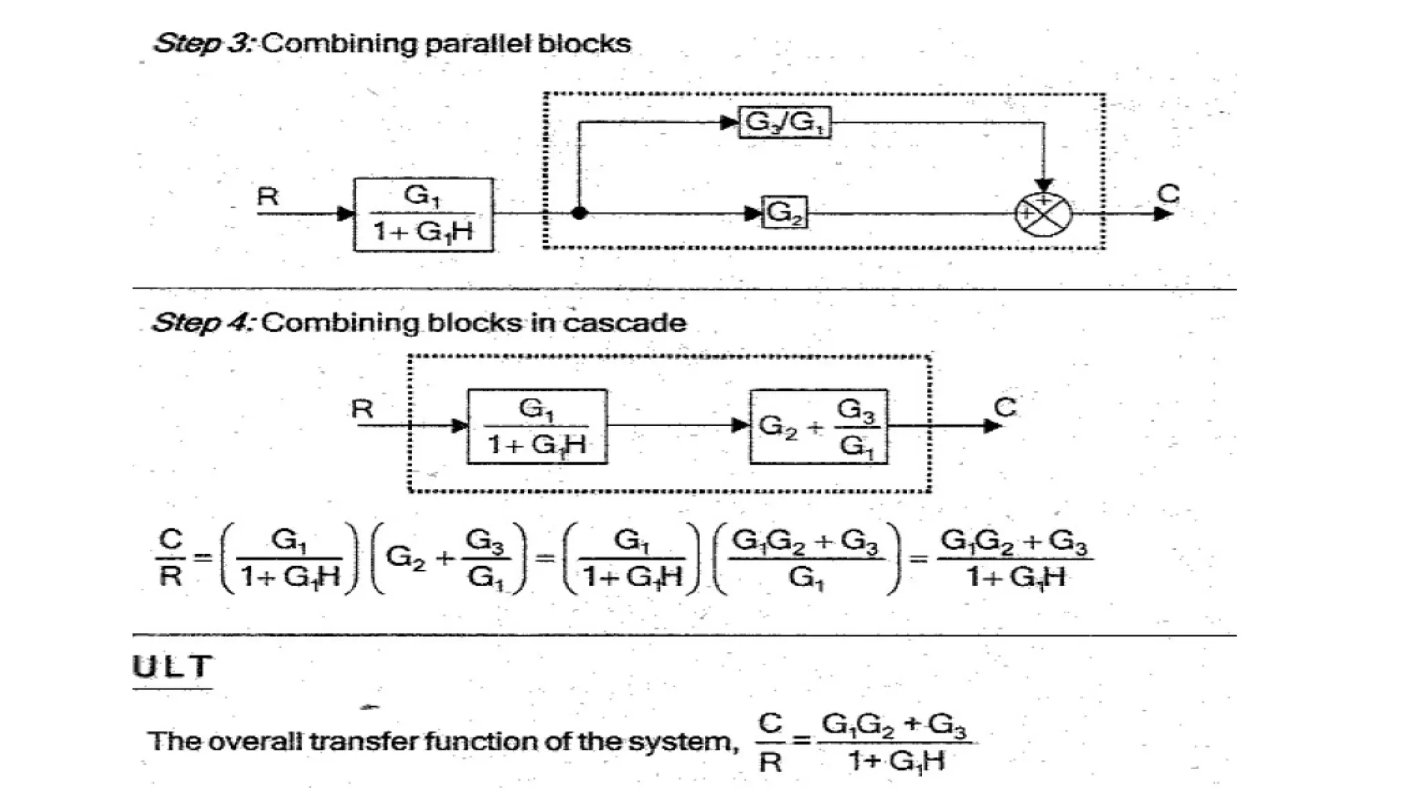
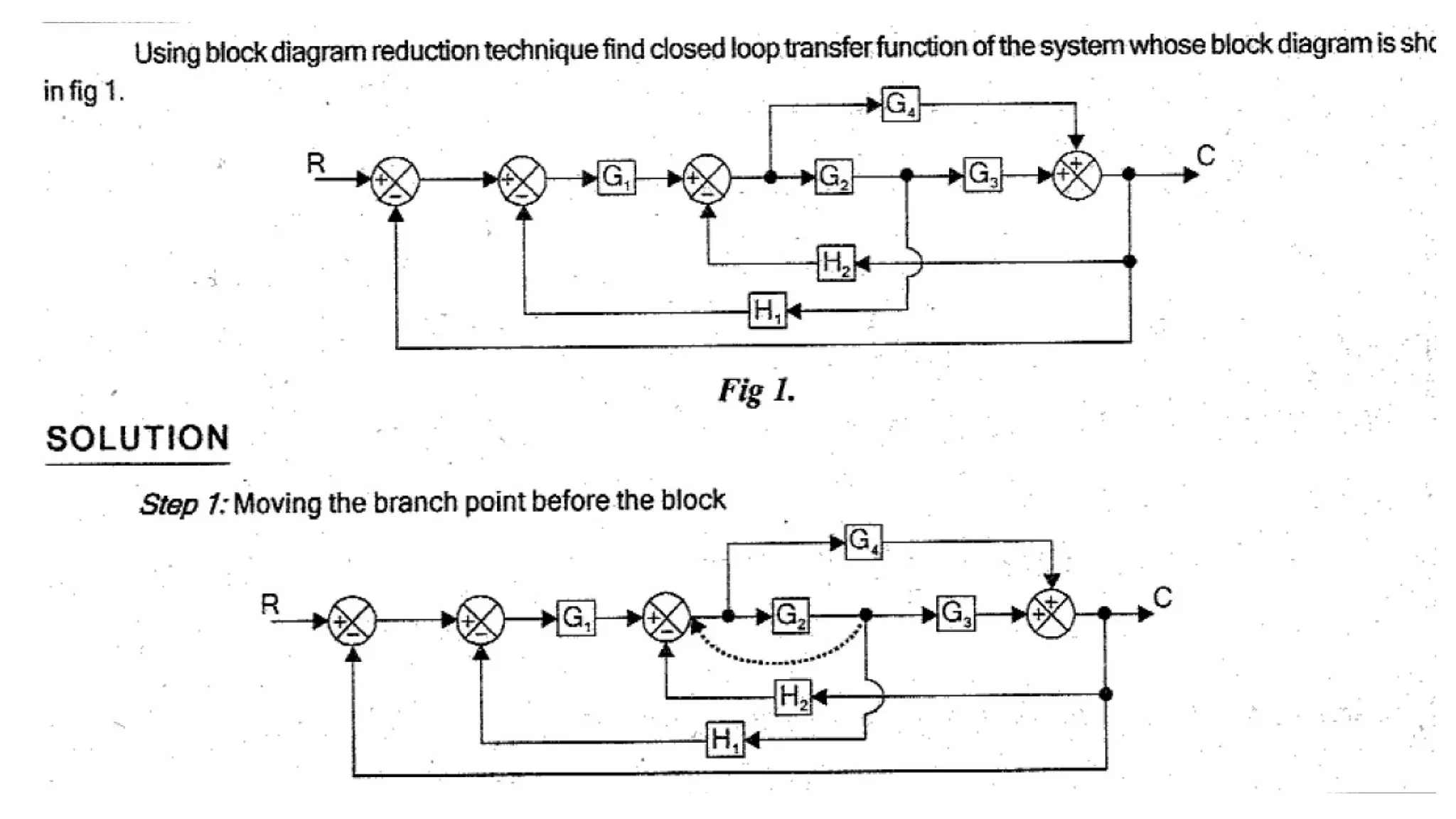
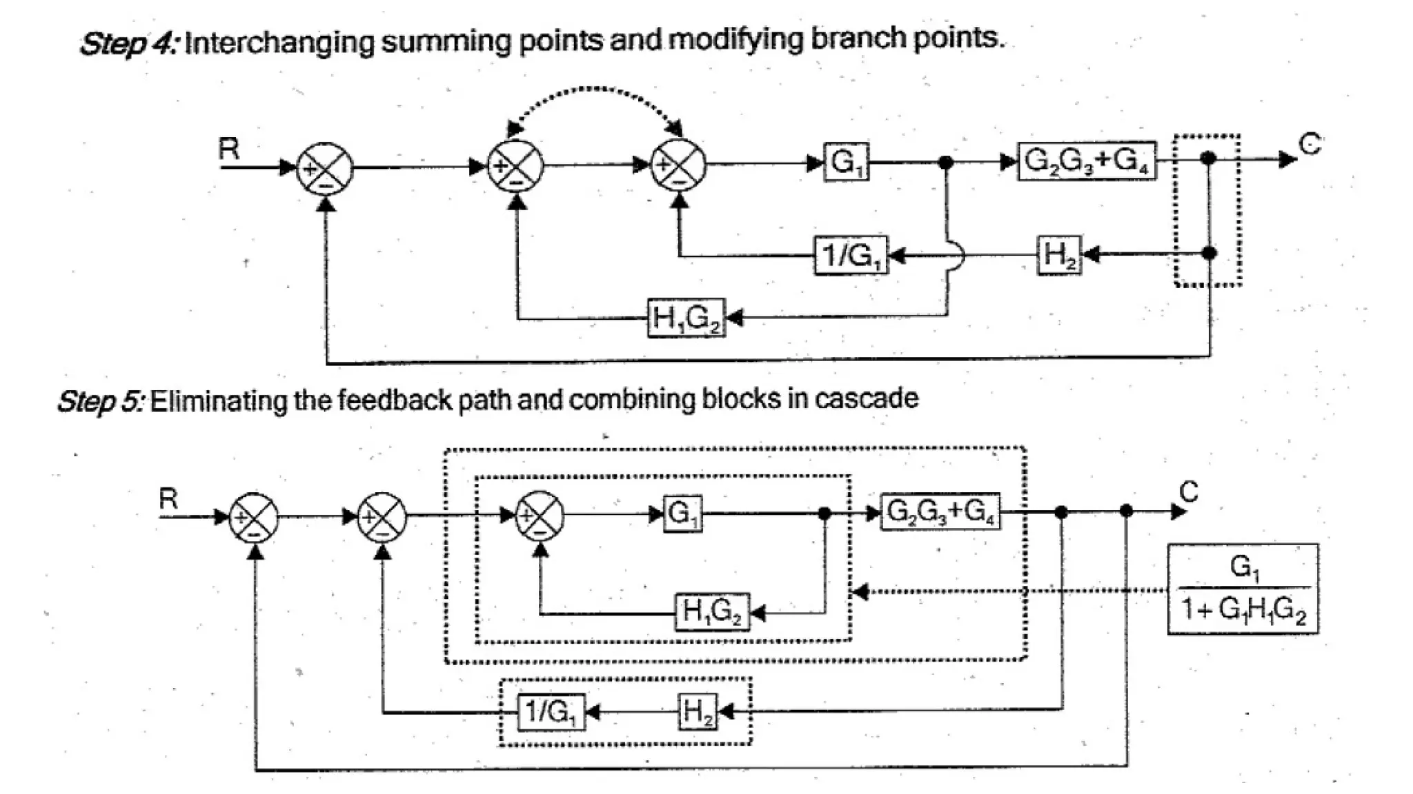
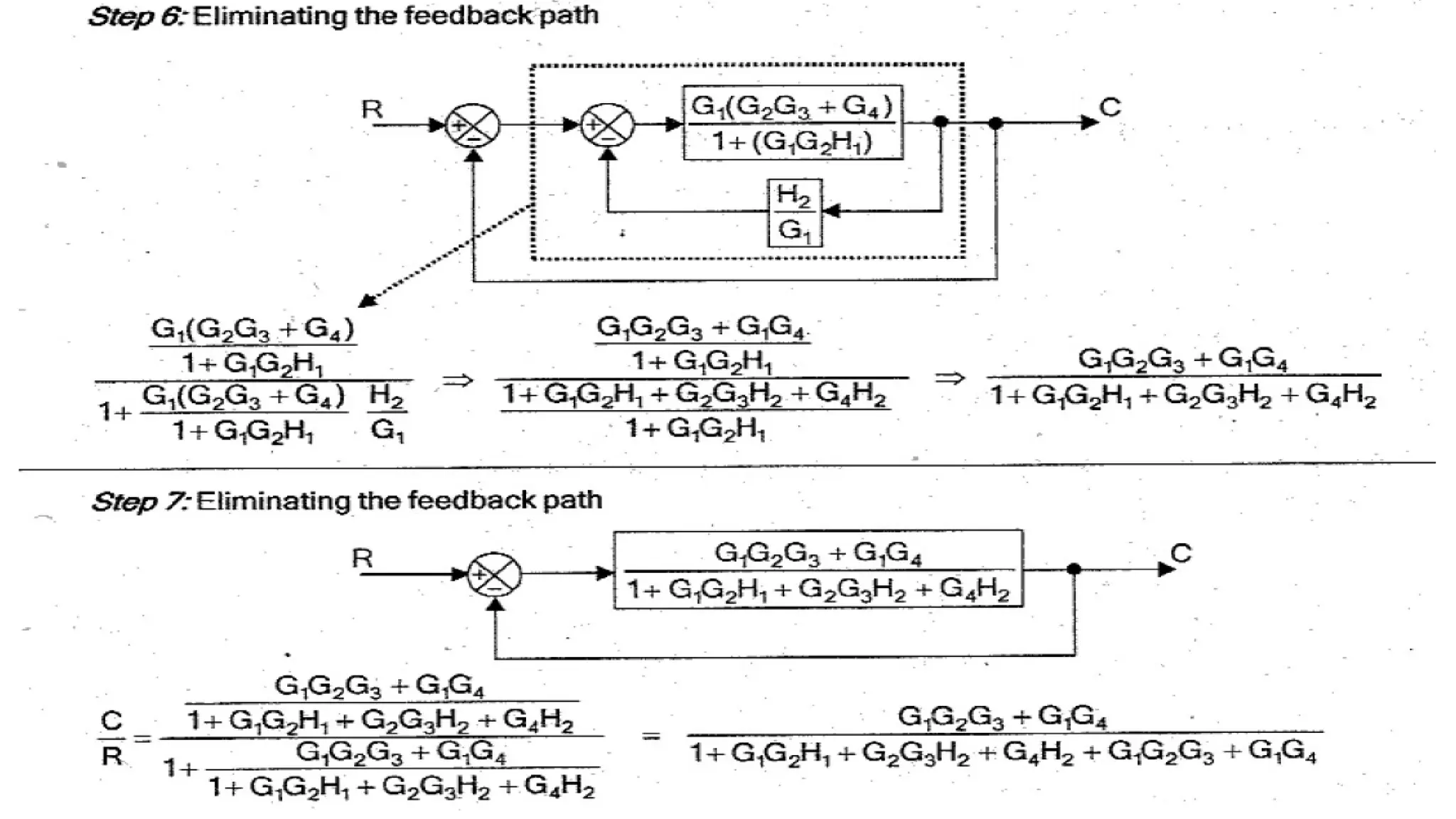
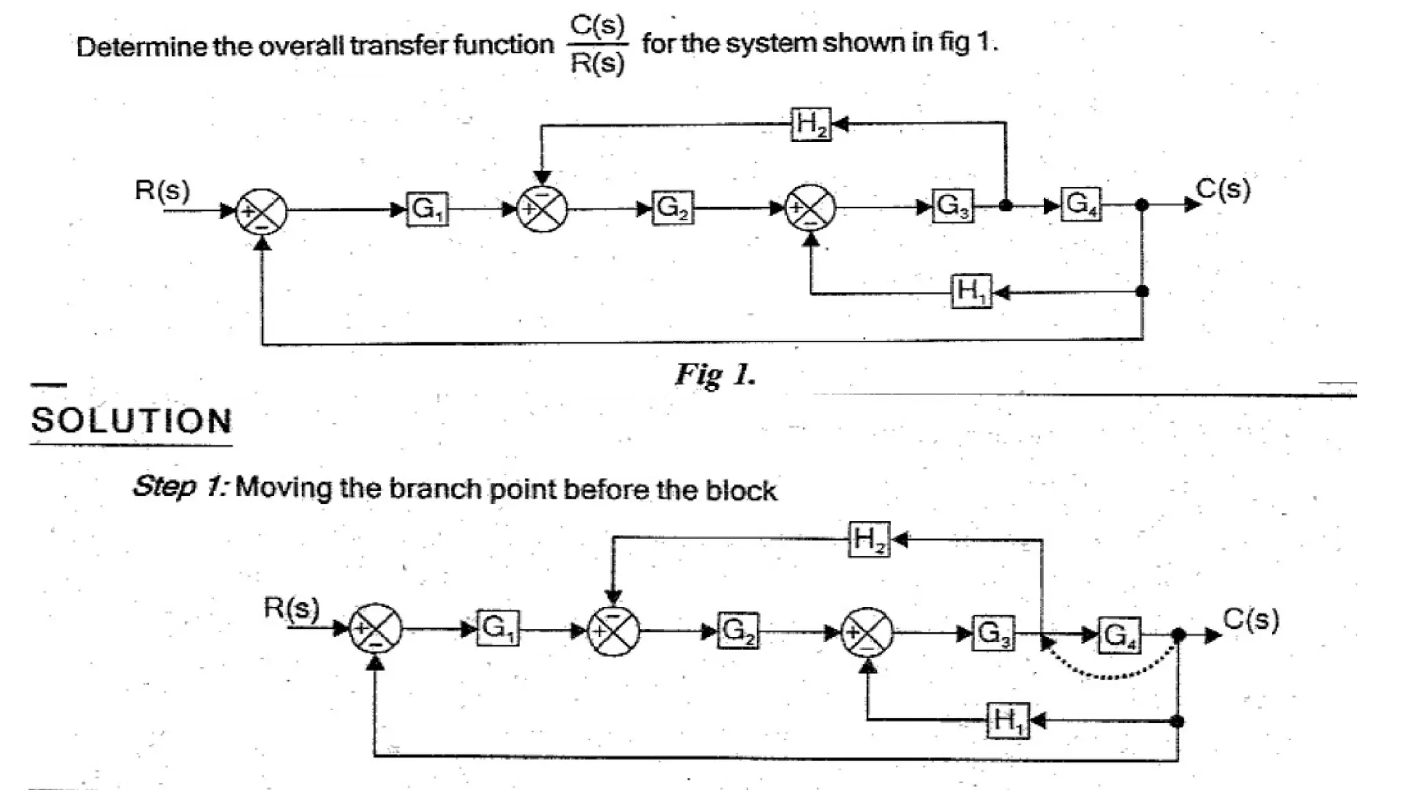
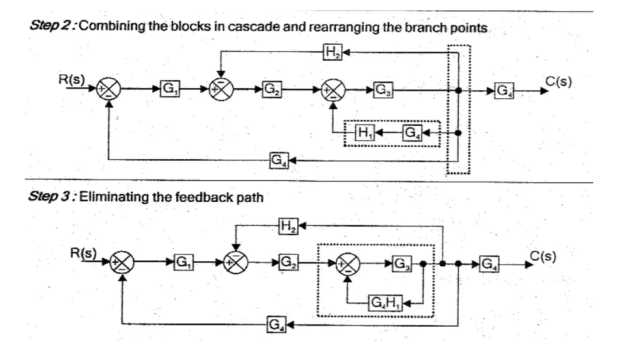
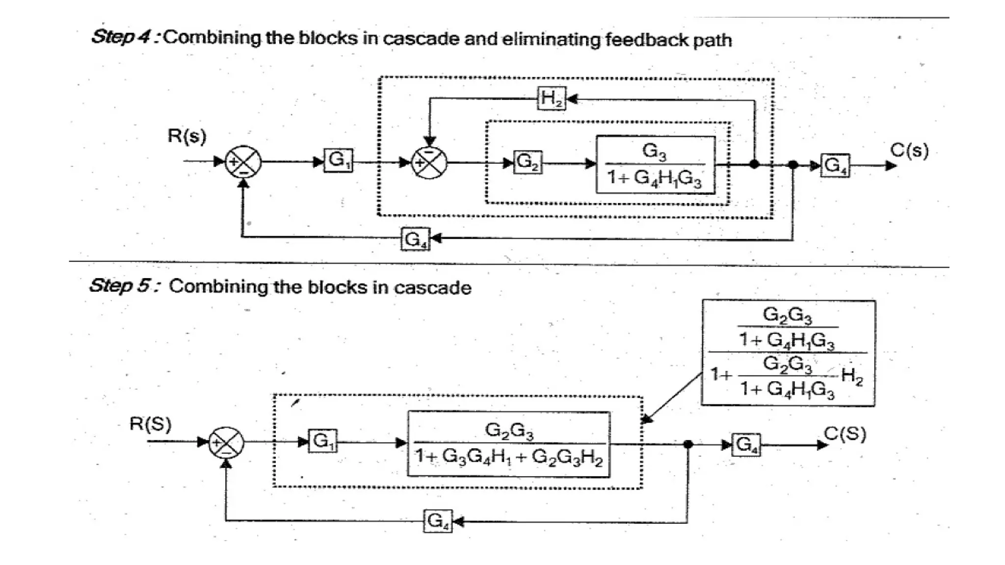
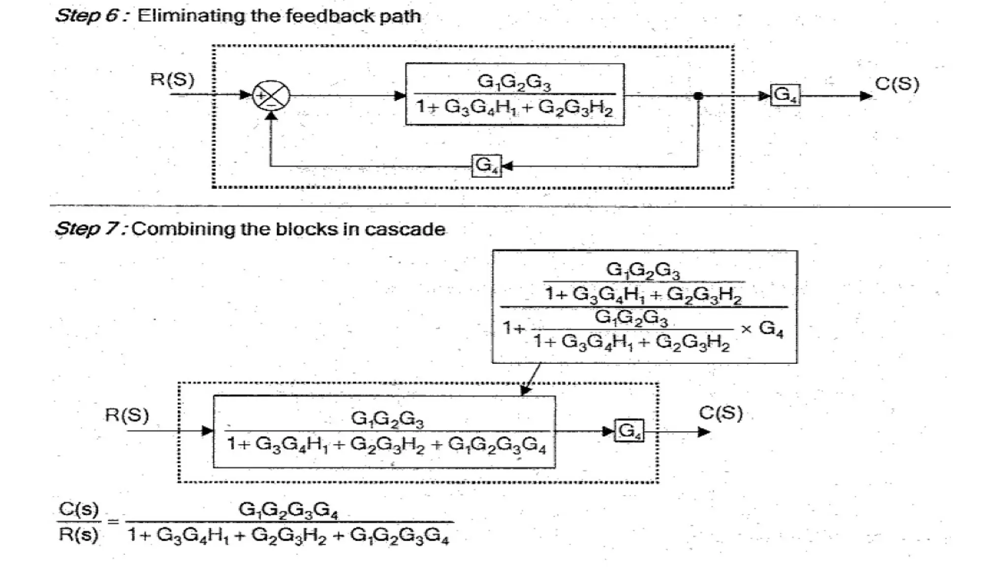
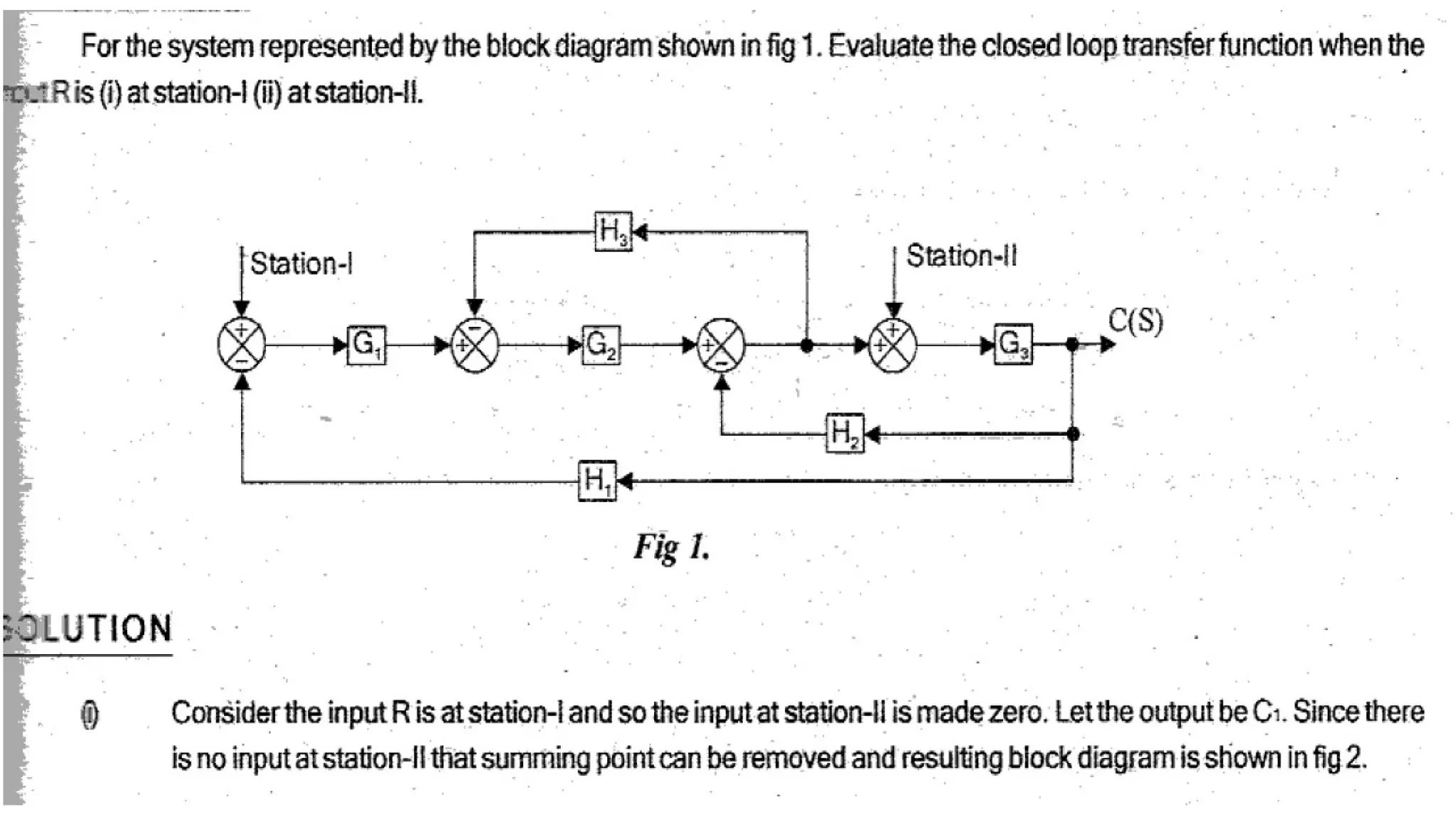
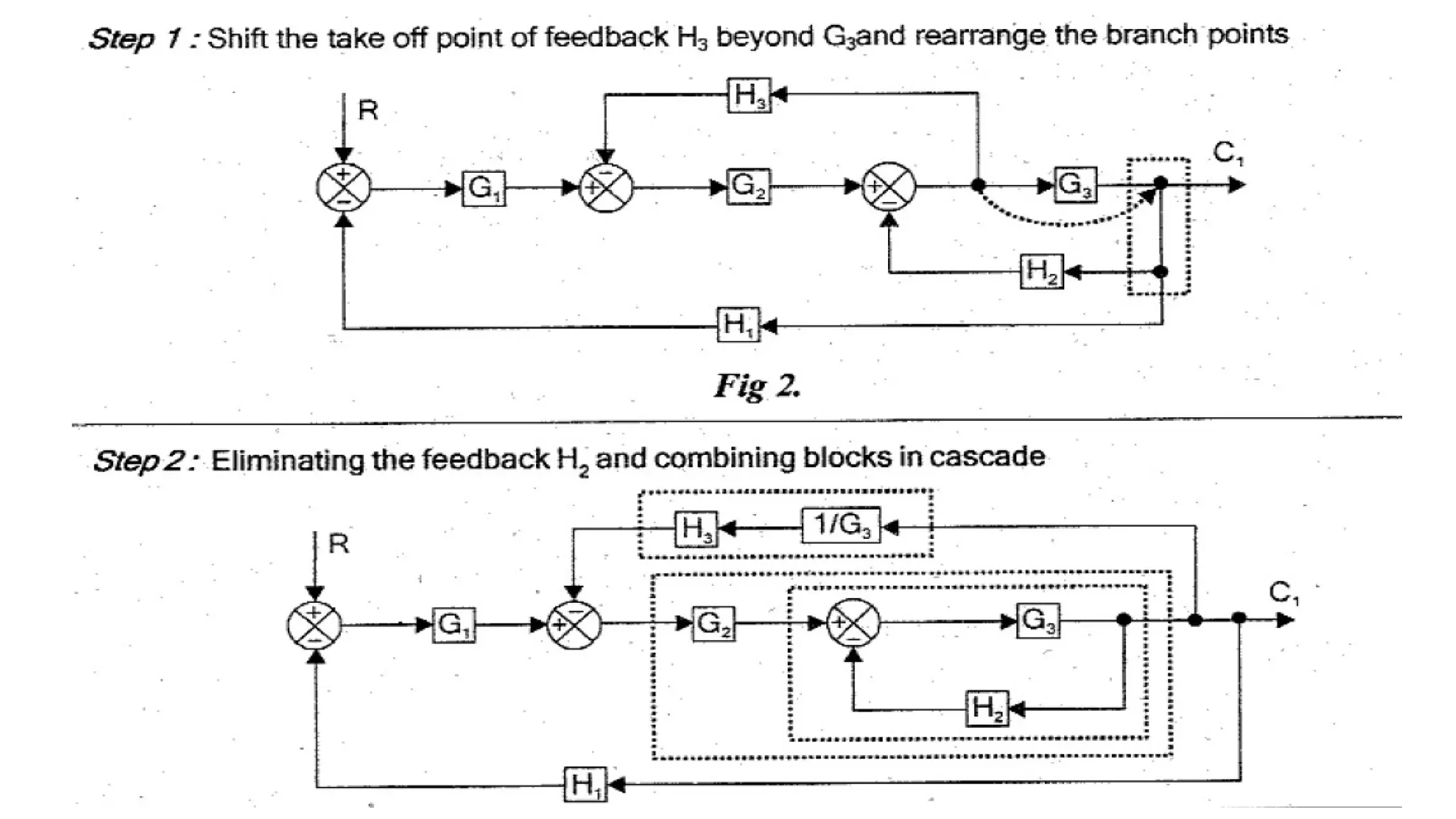
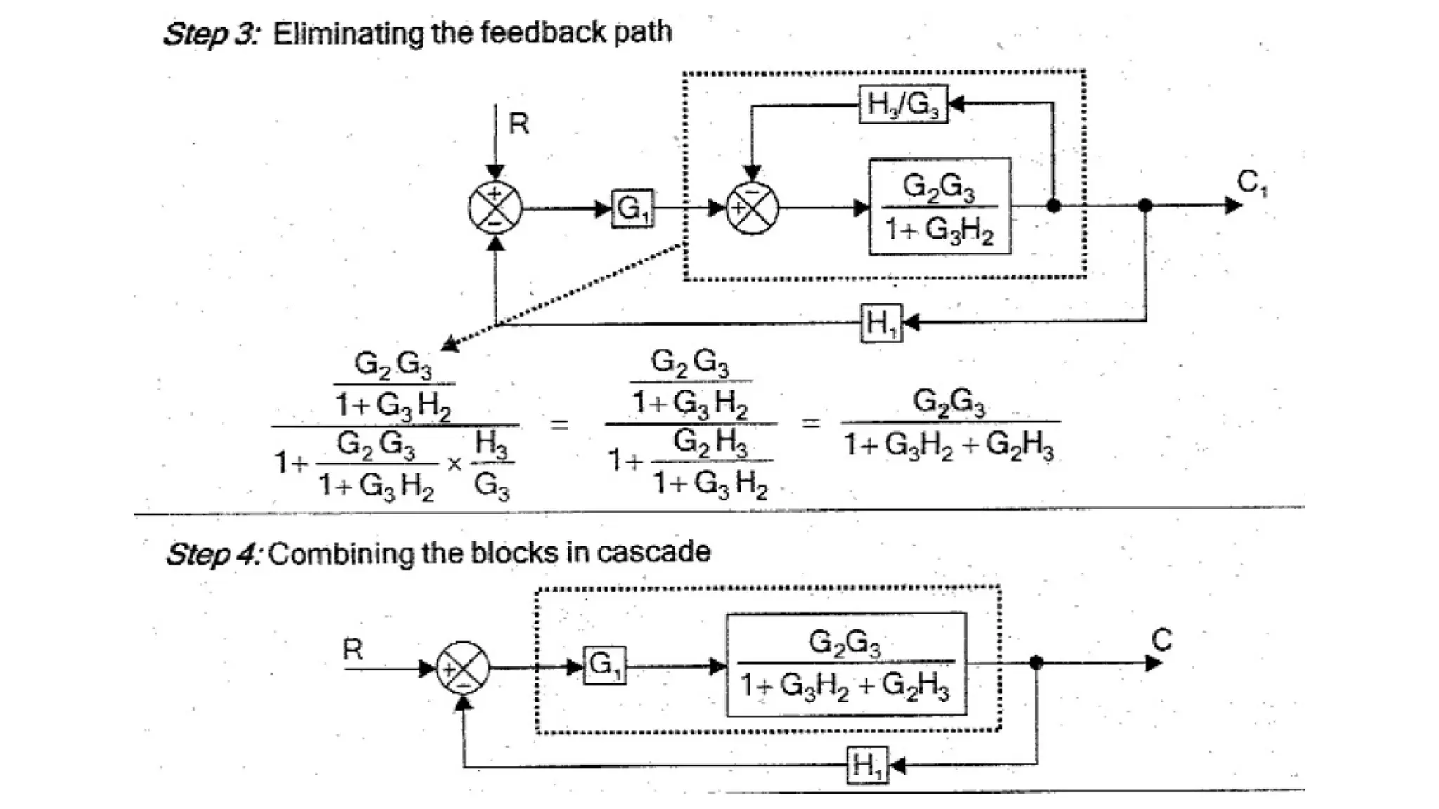
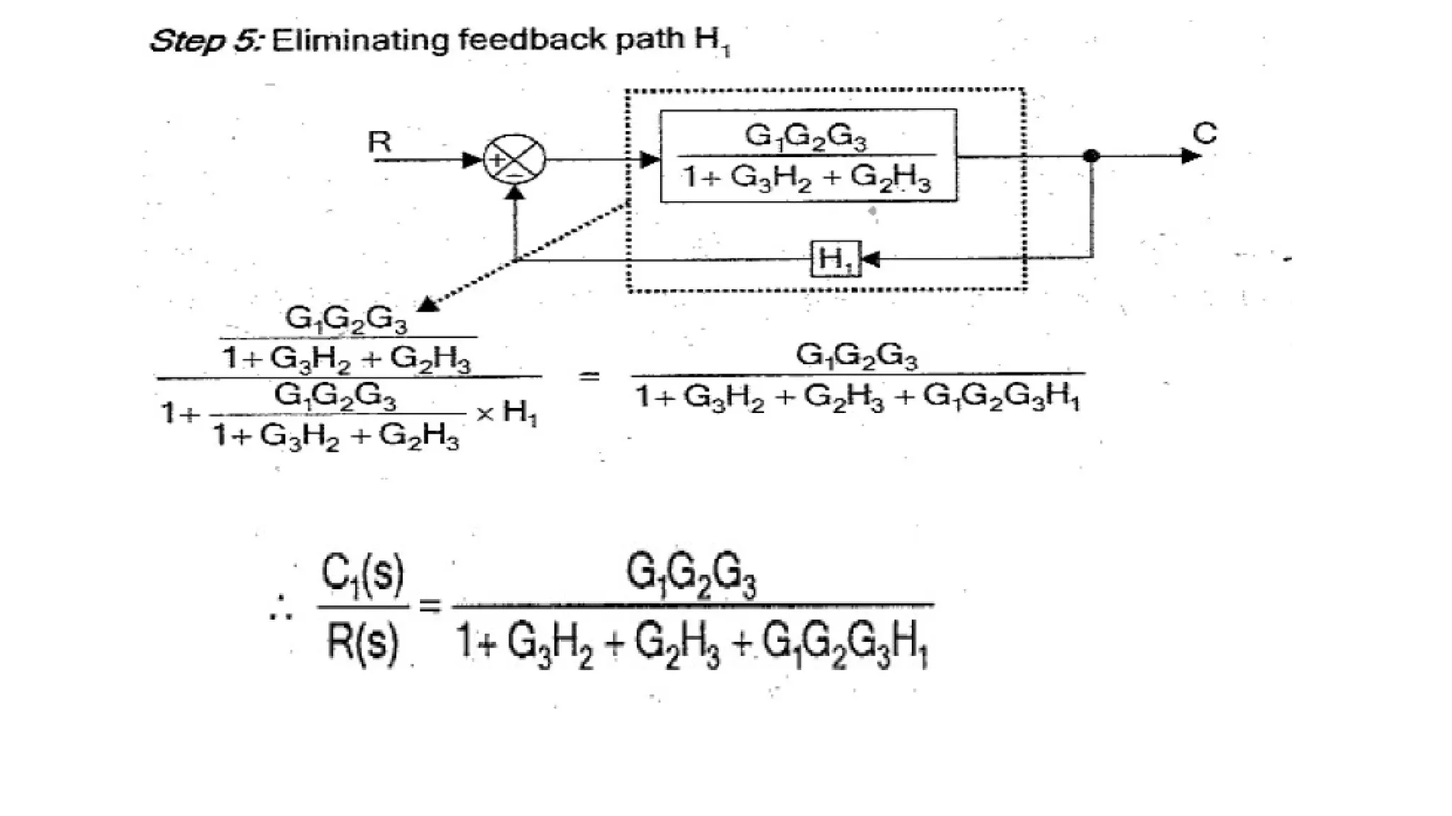
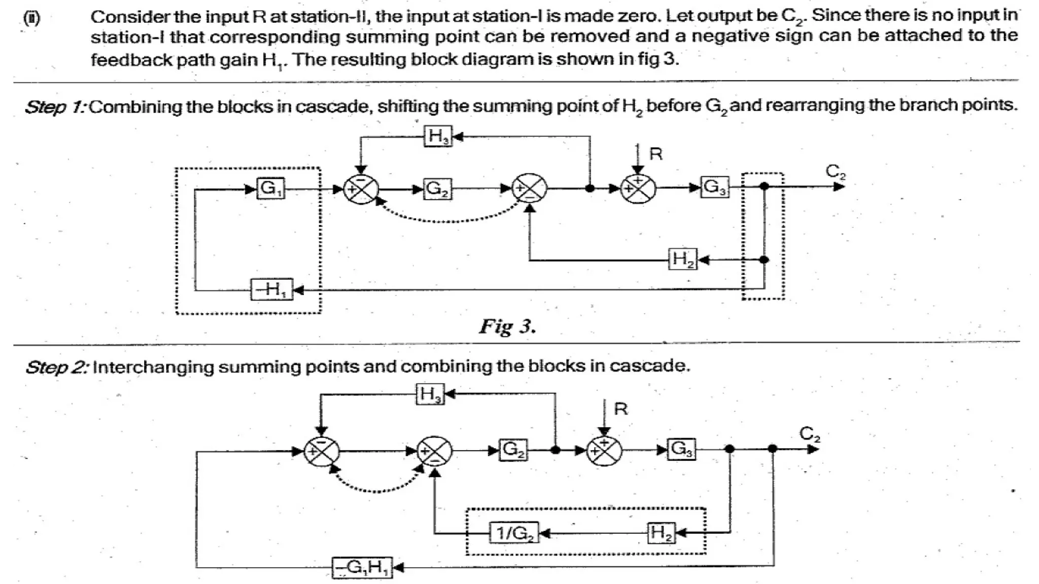
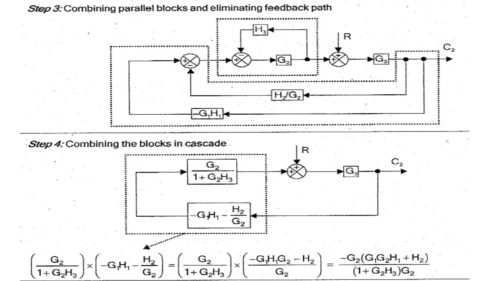
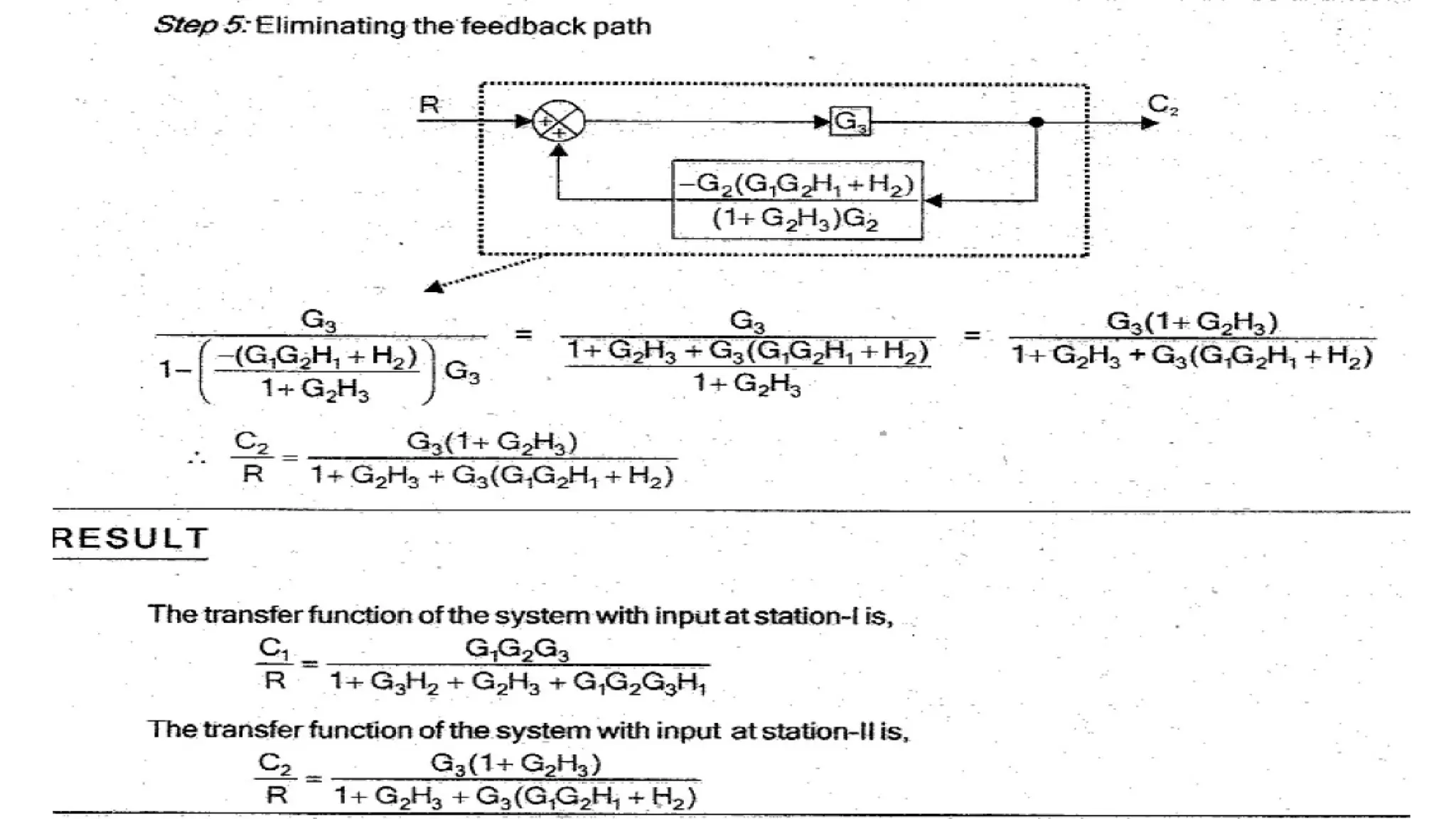
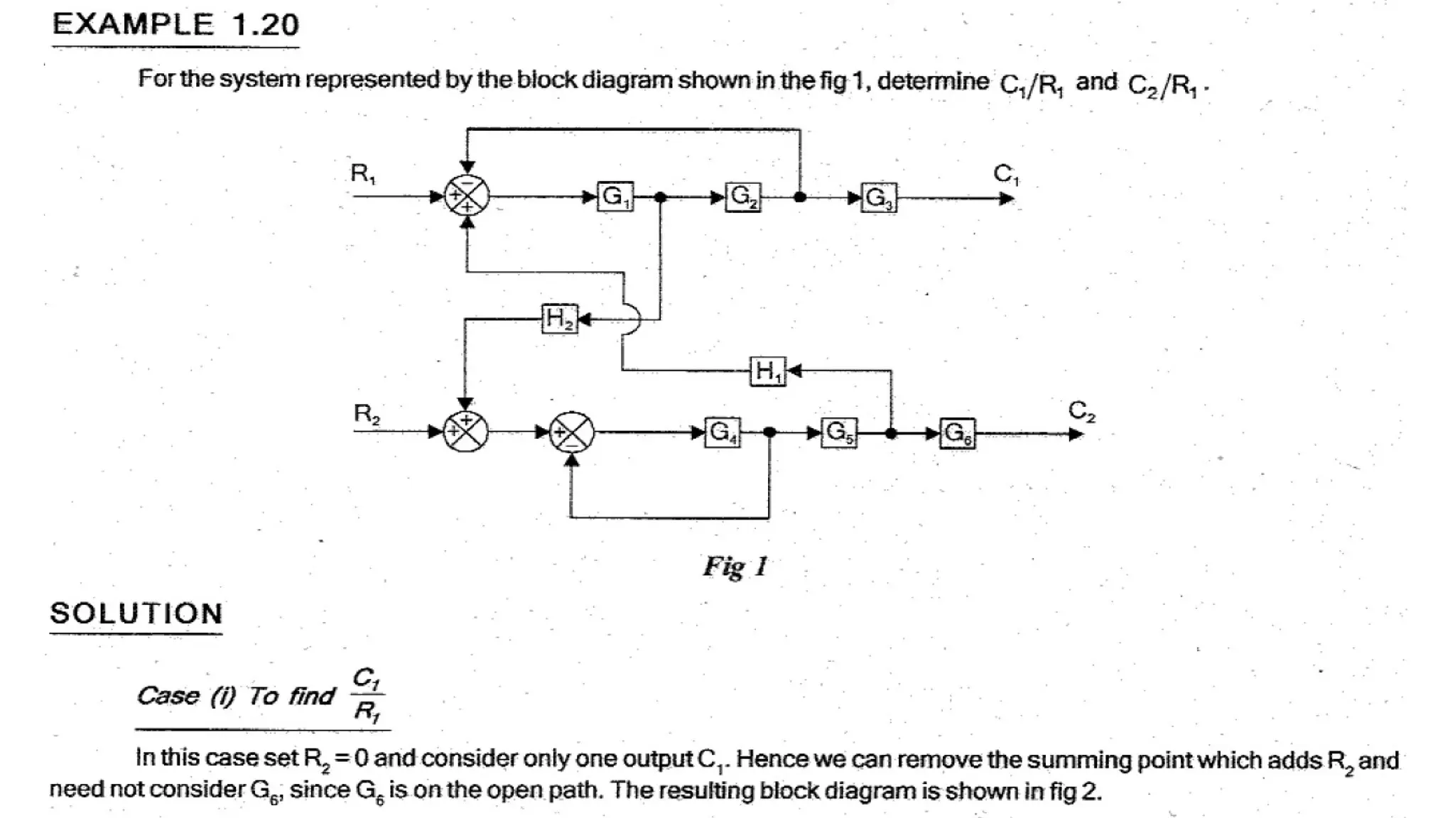
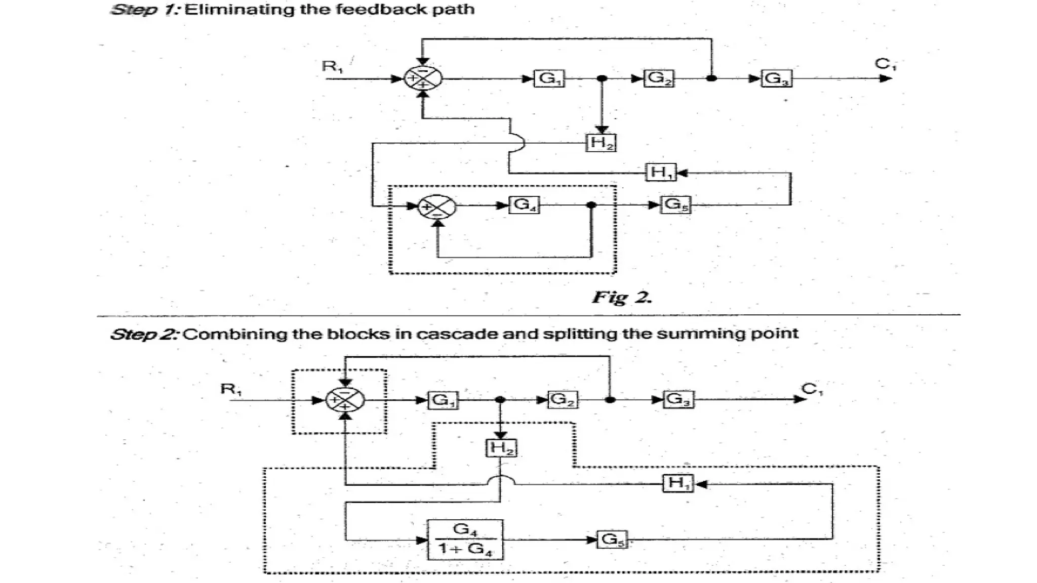
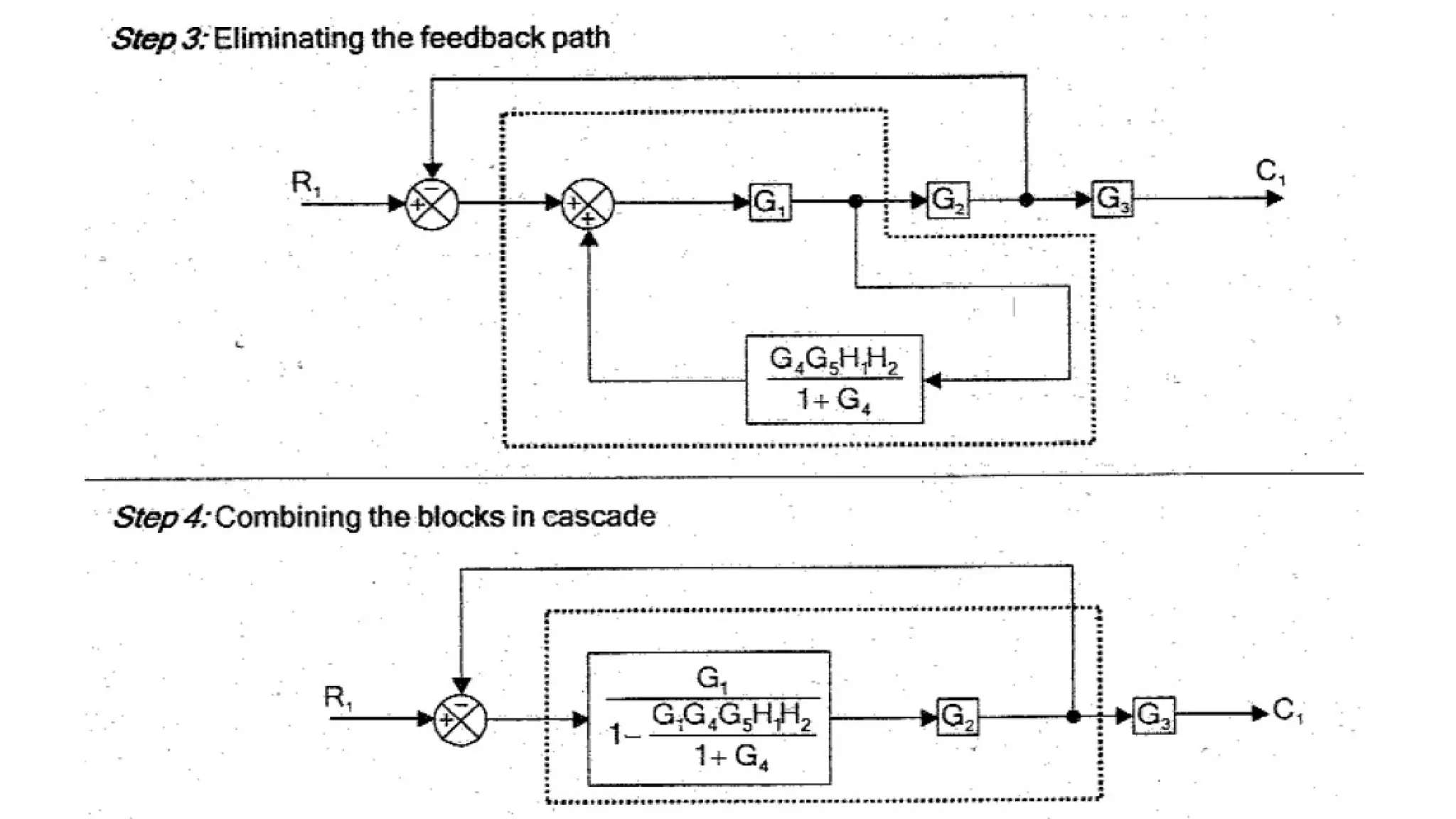
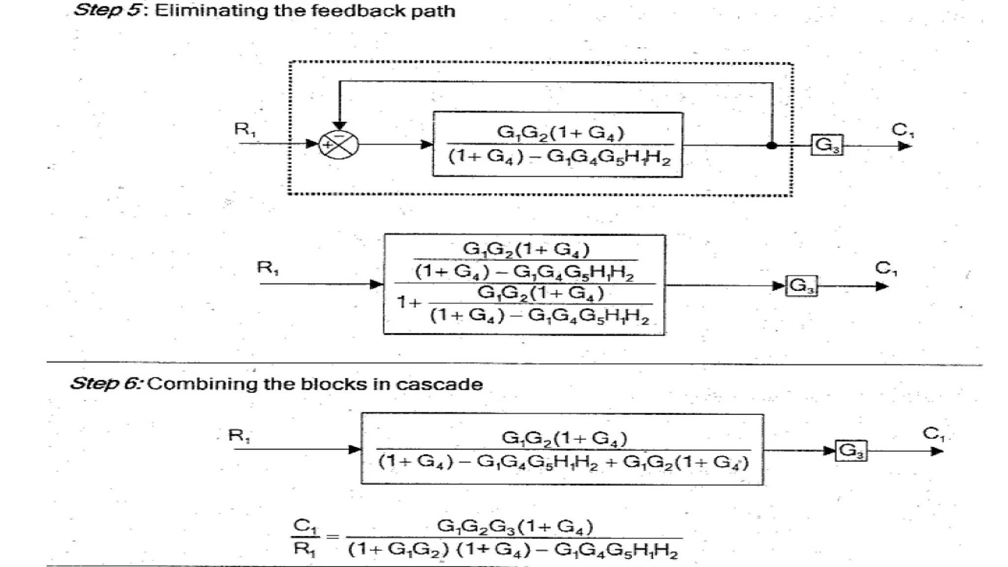
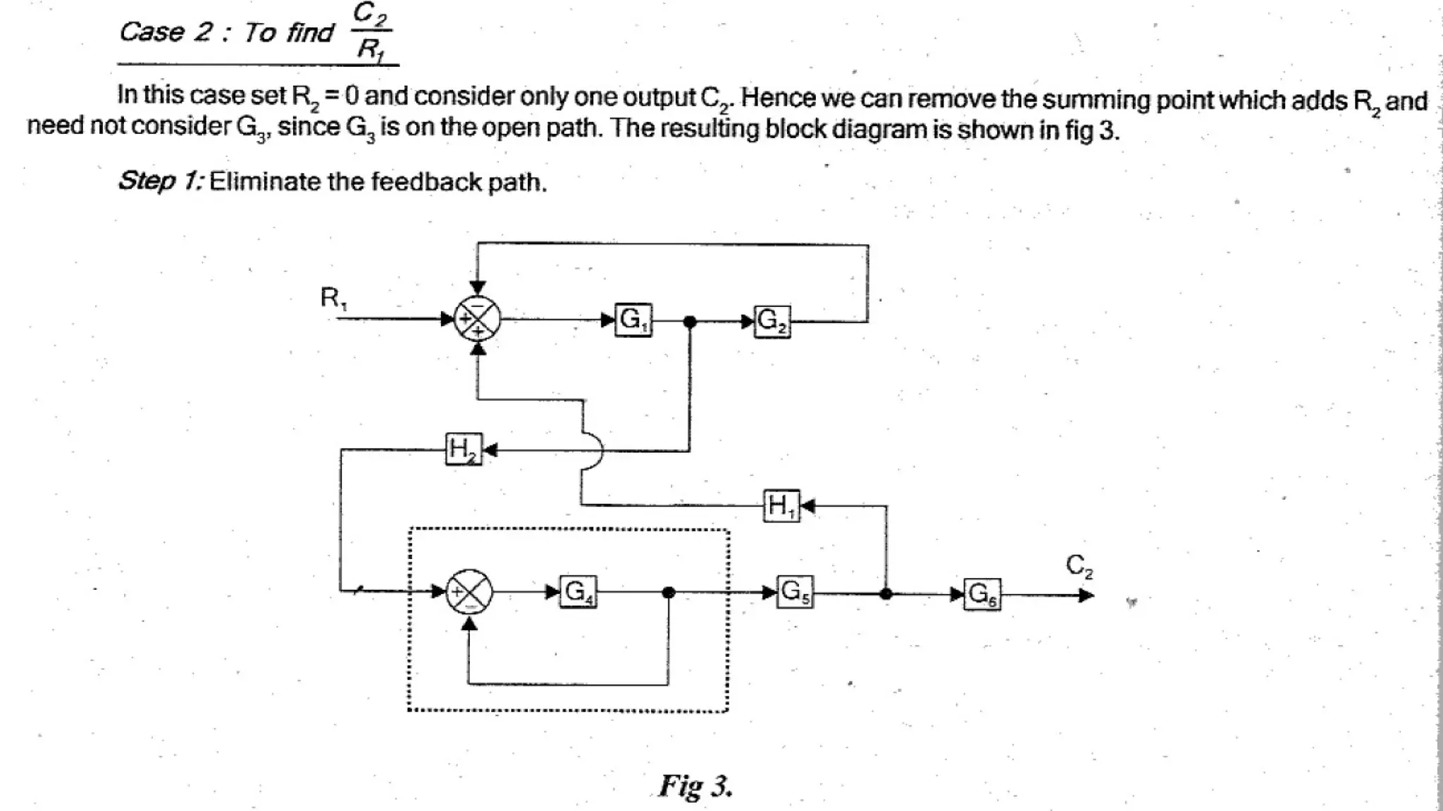
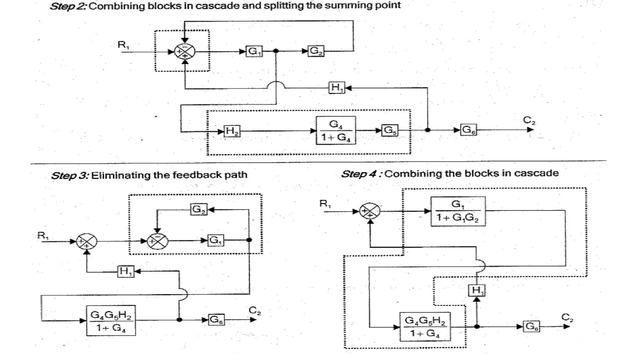
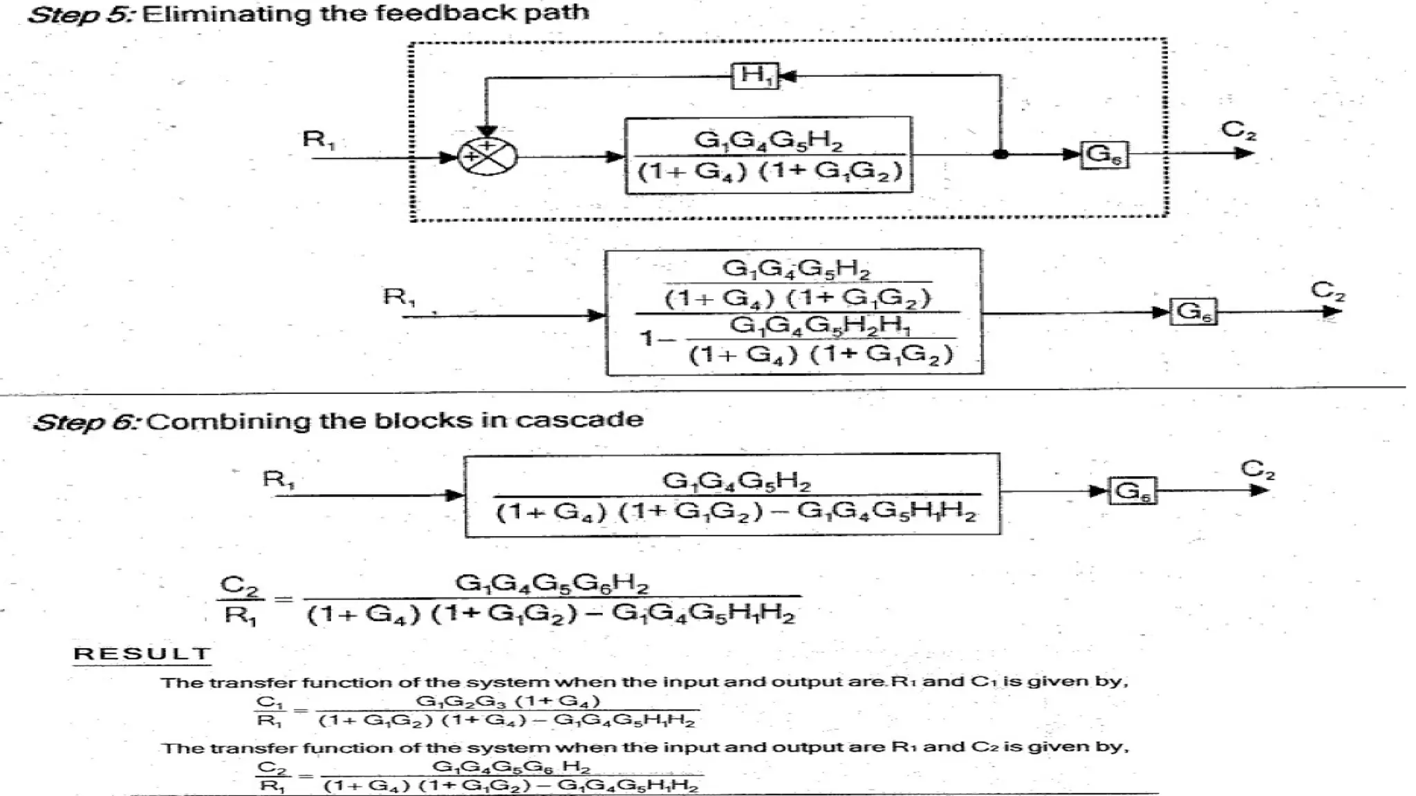
59.
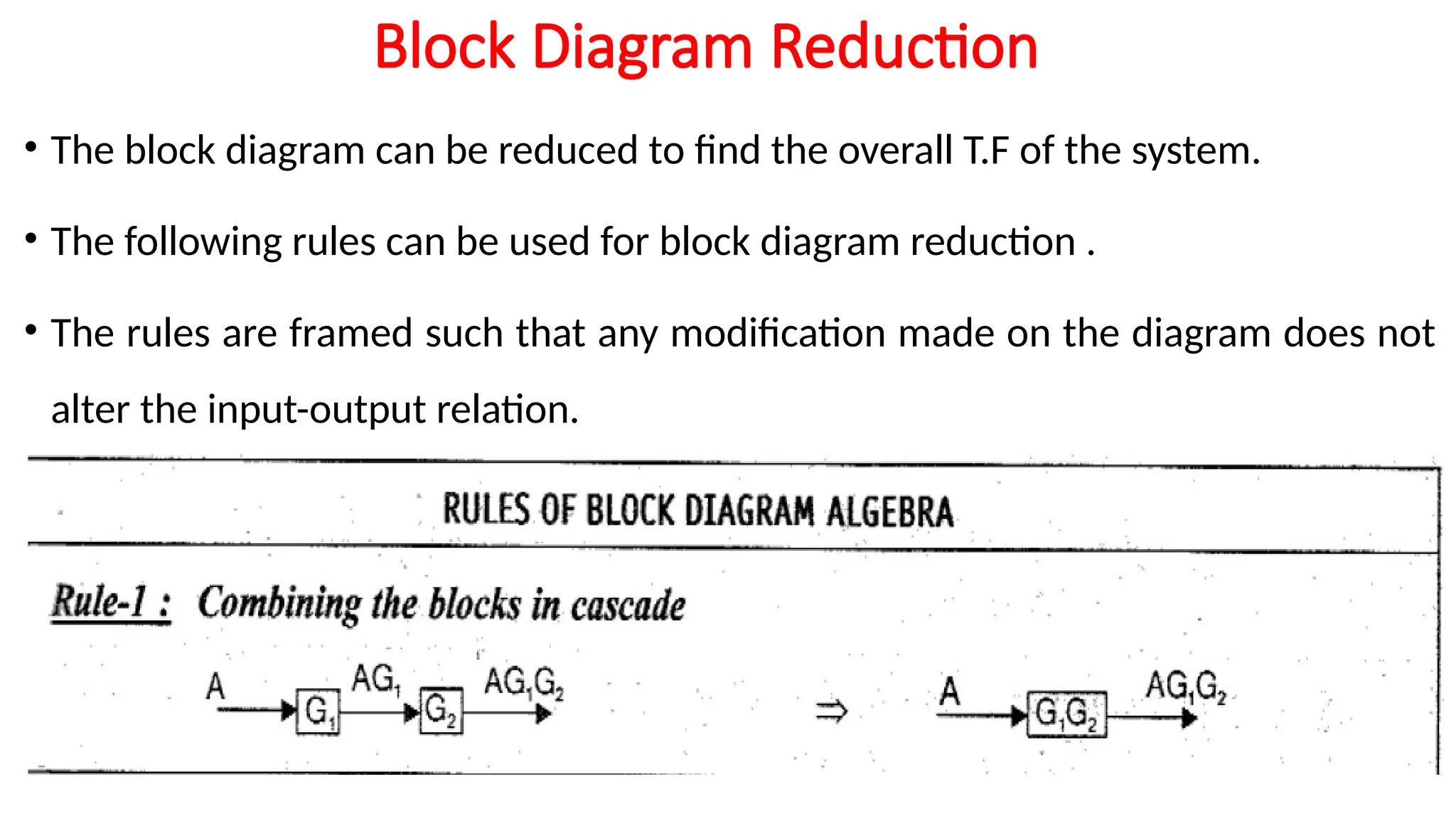
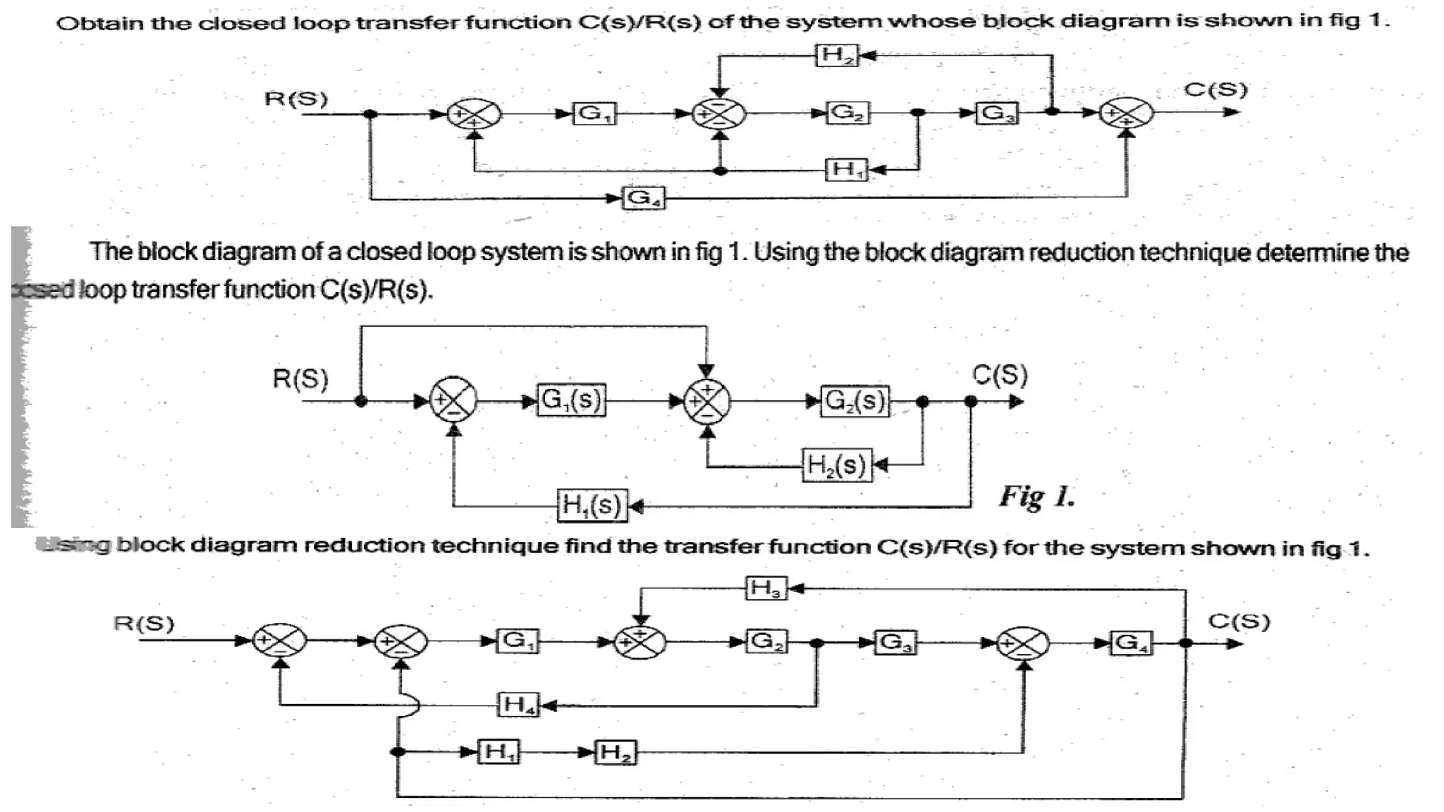
Block Diagram Reduction
•The block diagram can be reduced to find the overall T.F of the system.
• The following rules can be used for block diagram reduction .
• The rules are framed such that any modification made on the diagram does not
alter the input-output relation.
88.
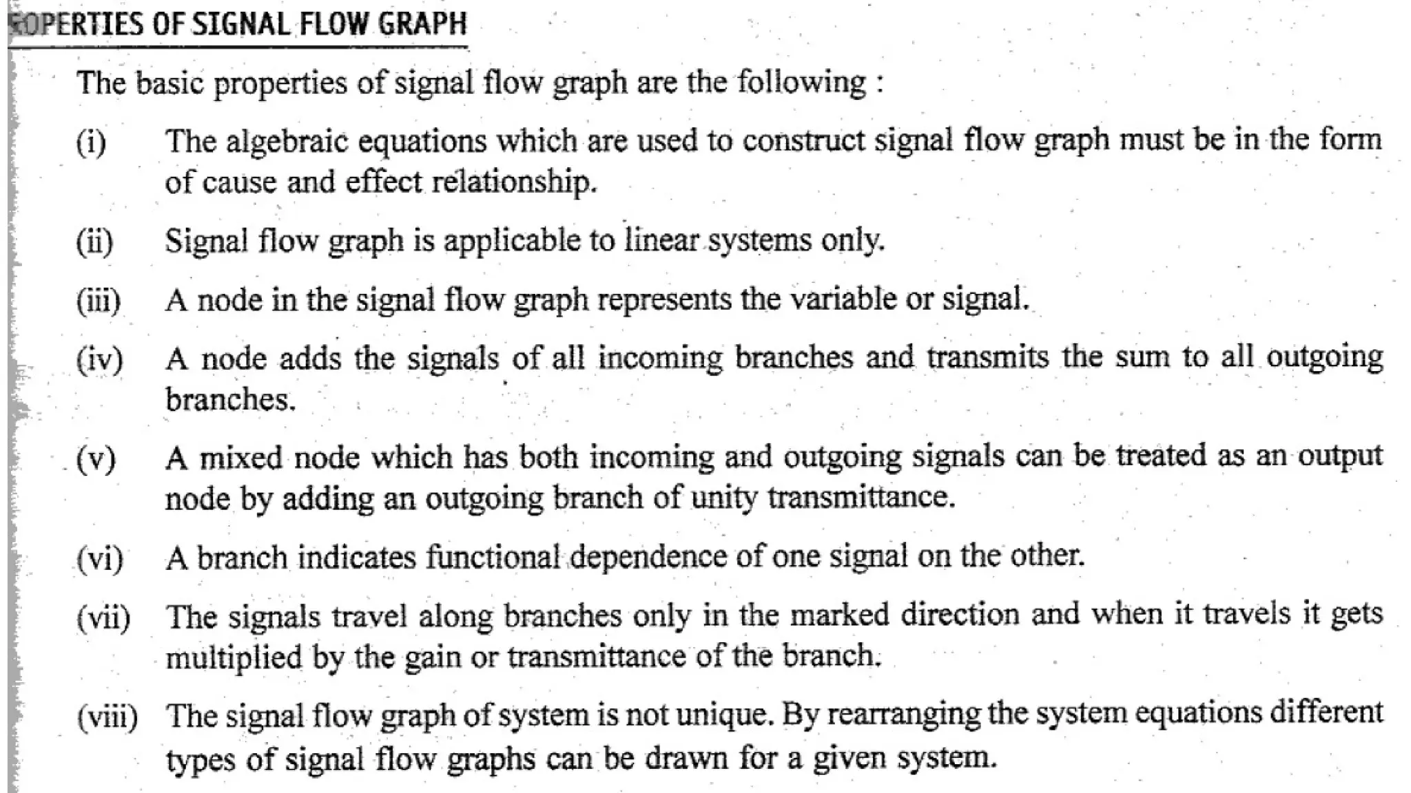
Signal Flow Graph(SFG)
•The SFG is used to represent the control system graphically and it was
developed by S.J.Mason.
• A SFG is a diagram that represents a set of simultaneous linear algebraic eqns.
• By taking L.T, the time domain D.Eqns governing a control system can be
transferred to a set of algebraic eqns in s-domain.
• The SFG & the block diagram approach yields the same information.
• The advantage of SFG is that, using Mason’s gain formula the overall gain of the
system can be computed easily.
89.
• The SFGdepicts the flow of signals from one point of system to another & gives the
relationship among the signals.
• A SFG consists of a n/w in which nodes are connected by directed branches.
• Each node represents a system variable & each branch connected b/w two nodes acts as
a signal multiplier.
• Each branch has a gain or transmittance. When signal passing through a branch, it gets
multiplied by the gain of the branch.
• In SFG, the signal flows in only one direction.
• The direction of signal flow is indicated by an arrow placed on the branch & the
gain(multiplication factor) is indicated along the branch.
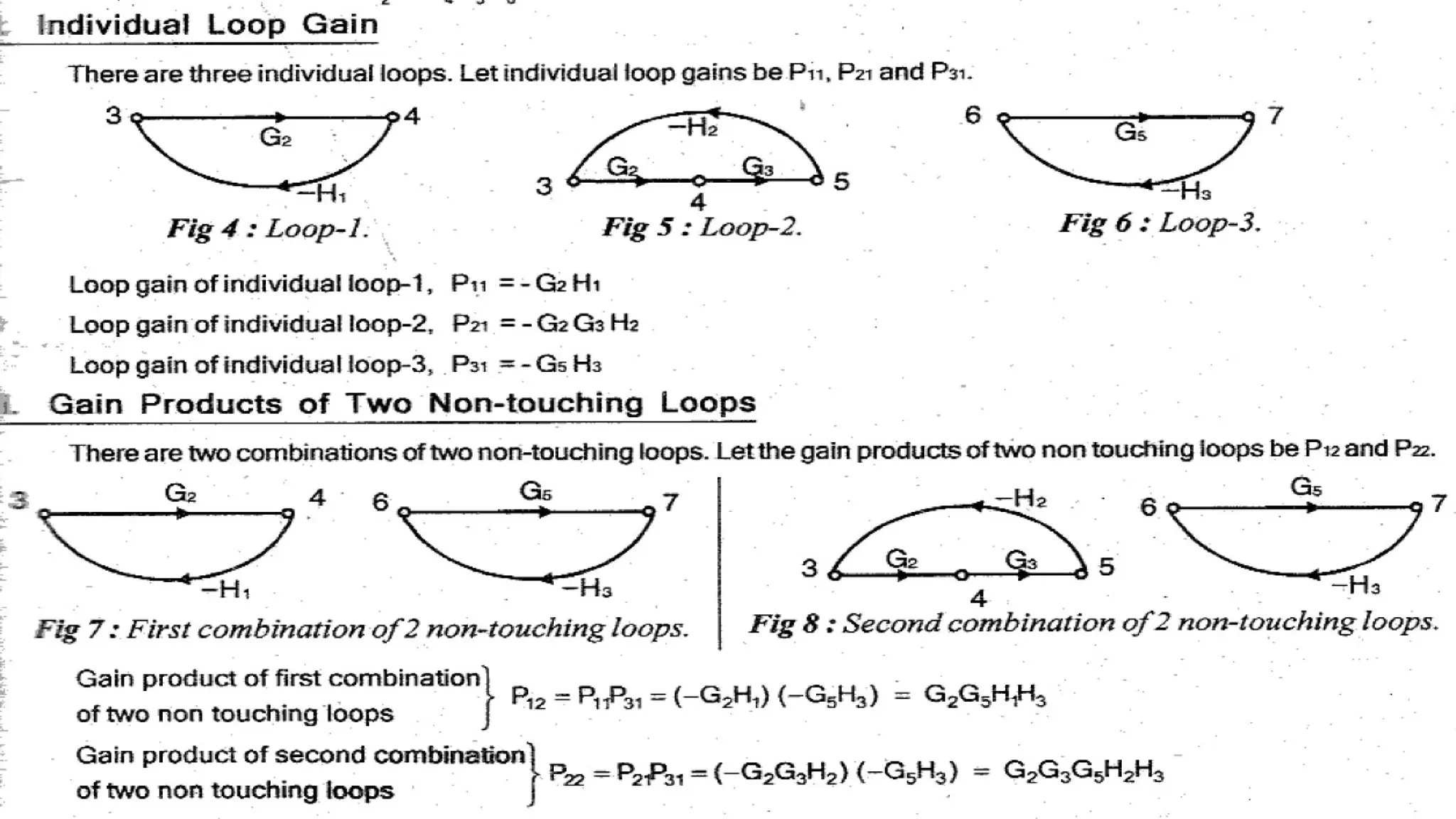
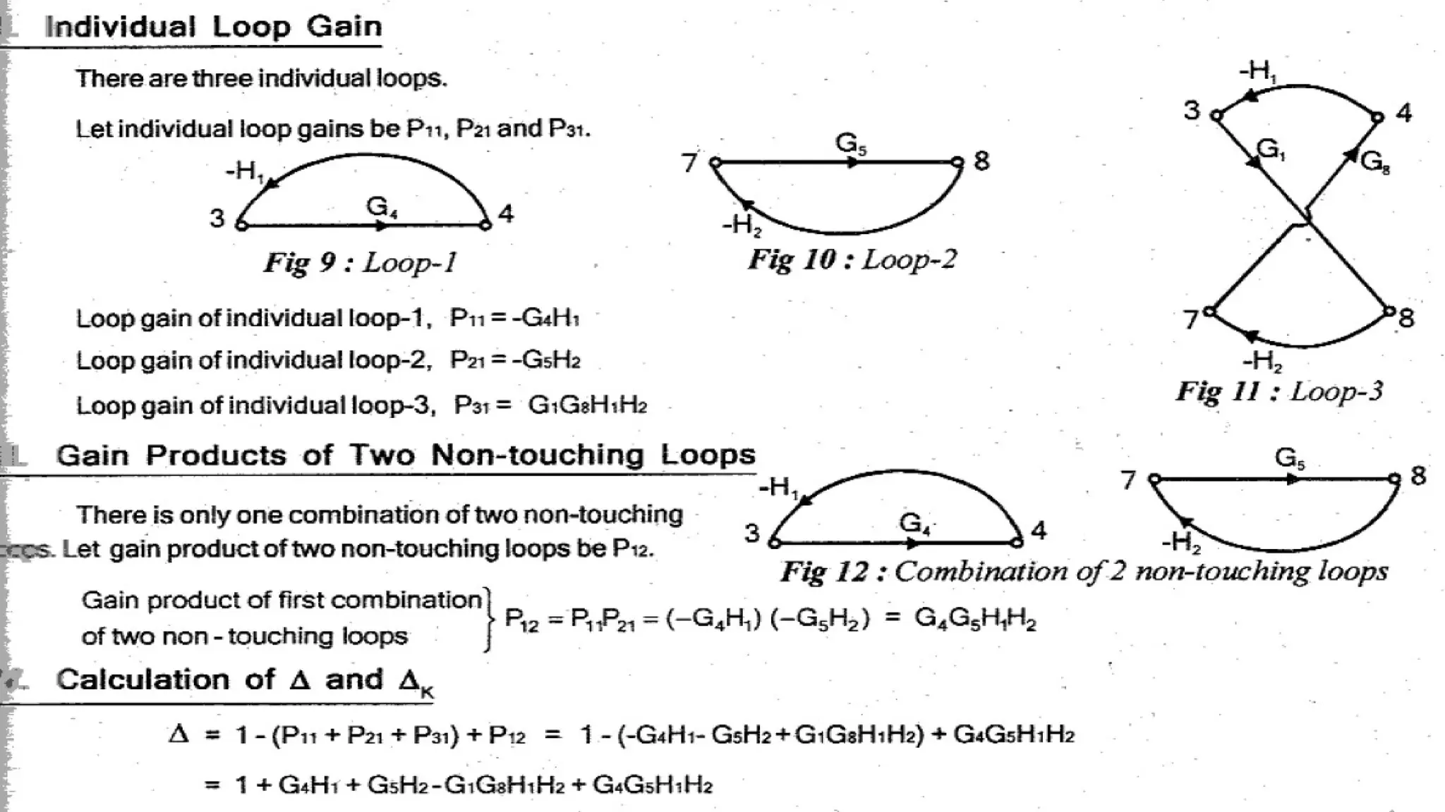
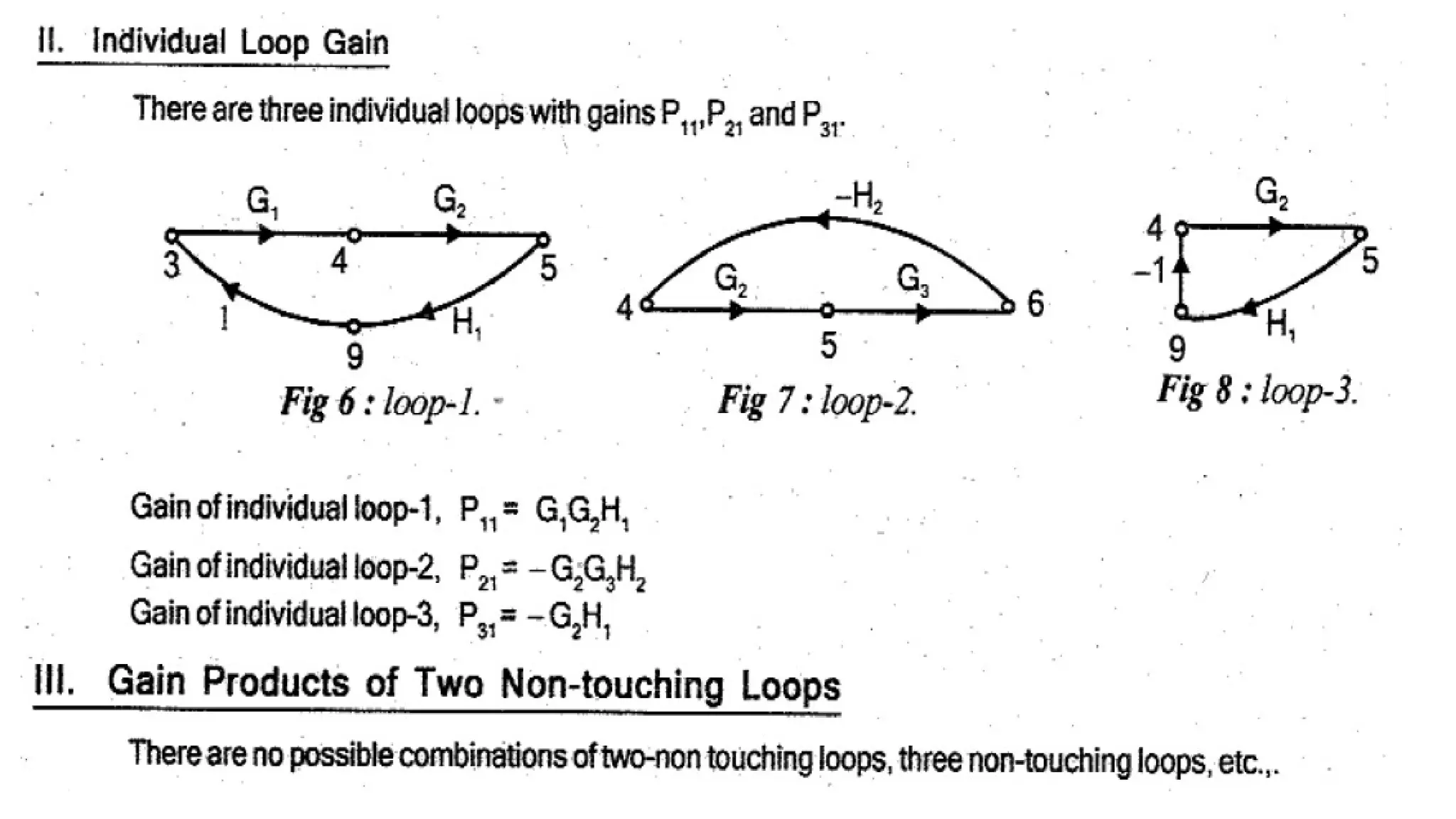
95.
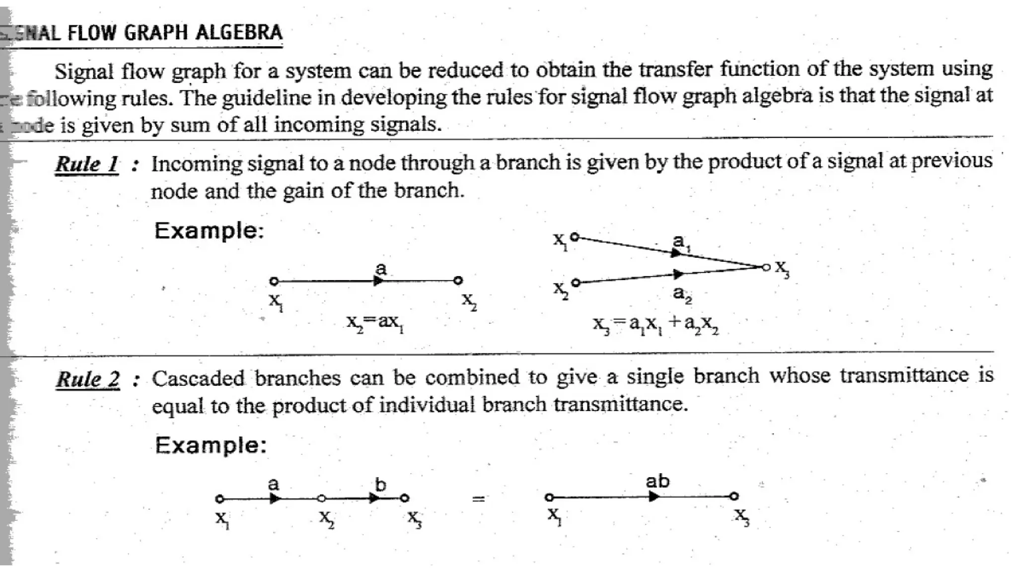
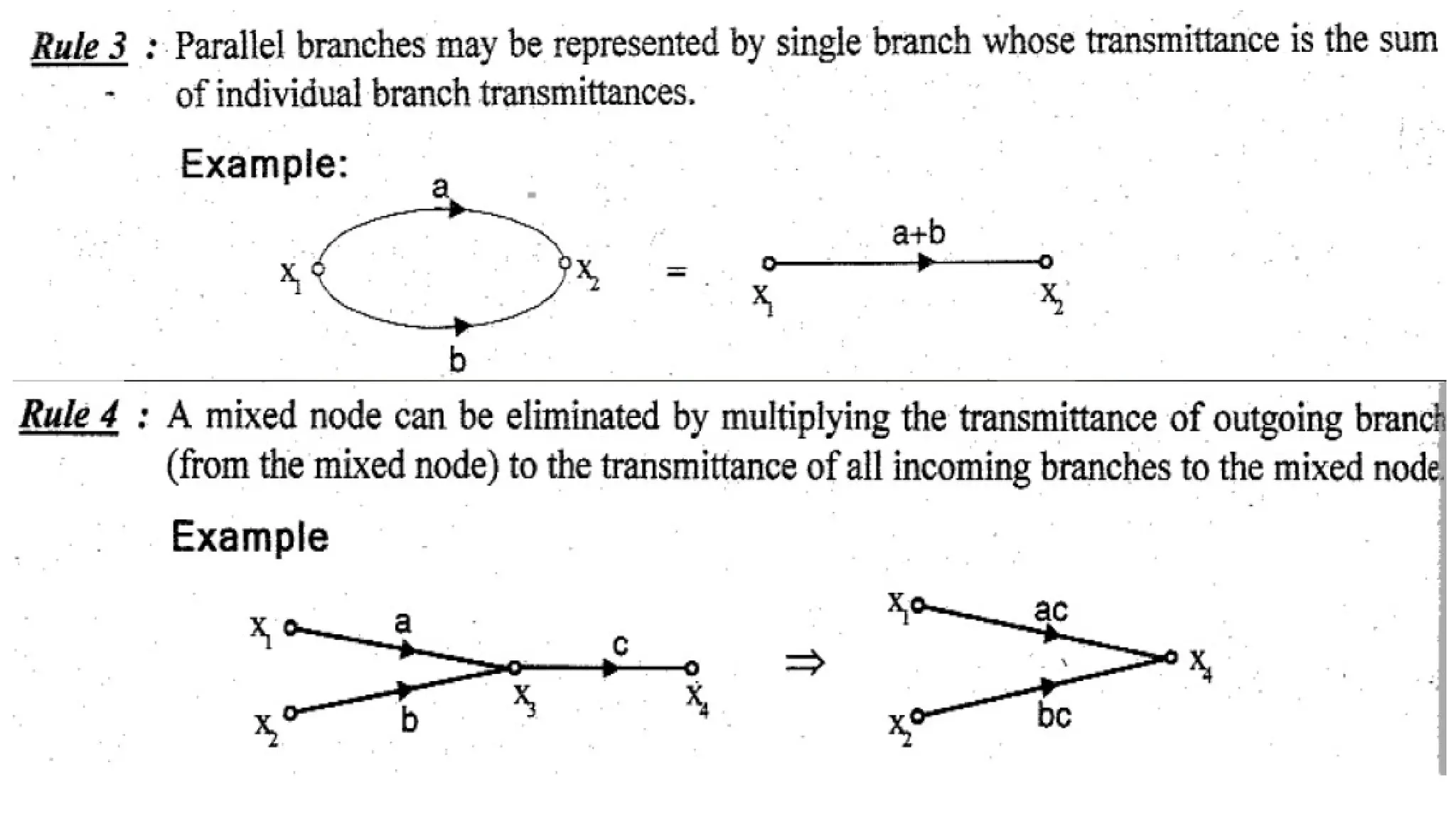
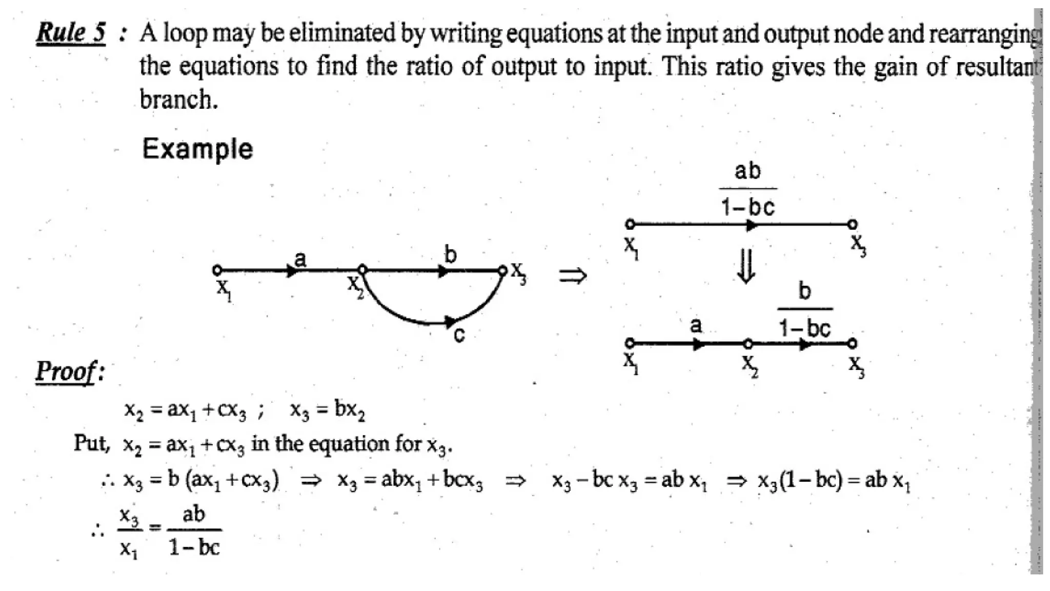
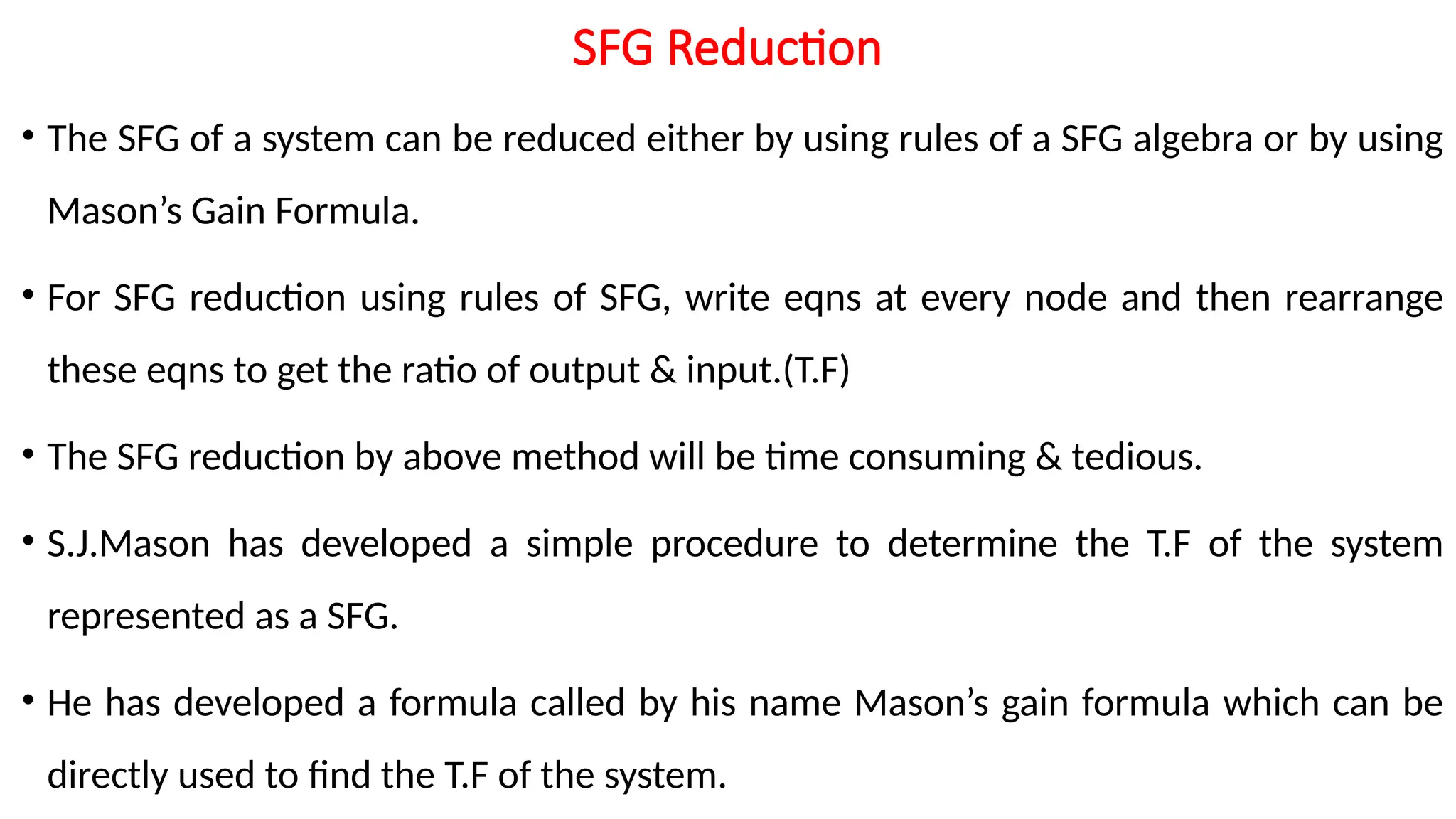
SFG Reduction
• TheSFG of a system can be reduced either by using rules of a SFG algebra or by using
Mason’s Gain Formula.
• For SFG reduction using rules of SFG, write eqns at every node and then rearrange
these eqns to get the ratio of output & input.(T.F)
• The SFG reduction by above method will be time consuming & tedious.
• S.J.Mason has developed a simple procedure to determine the T.F of the system
represented as a SFG.
• He has developed a formula called by his name Mason’s gain formula which can be
directly used to find the T.F of the system.
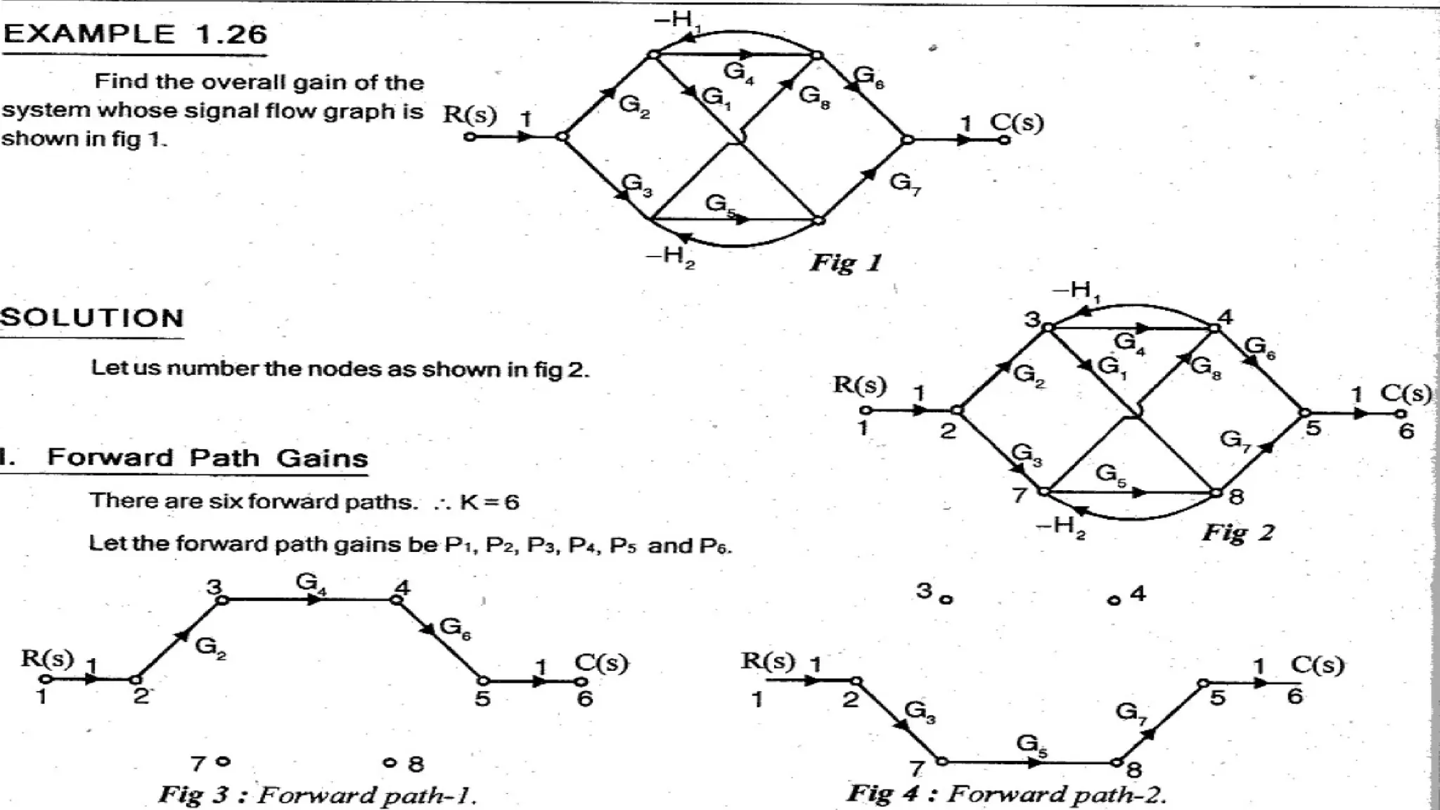
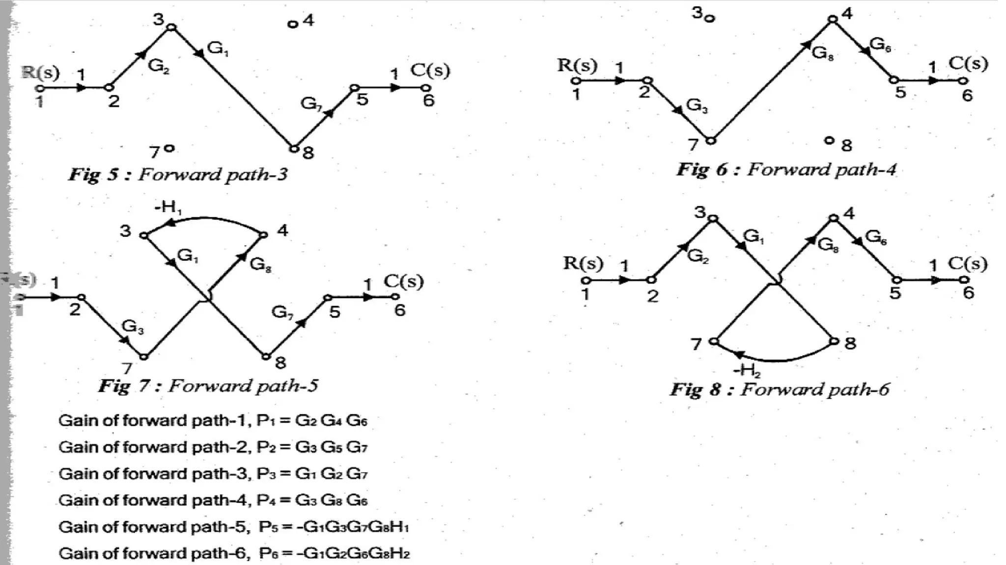
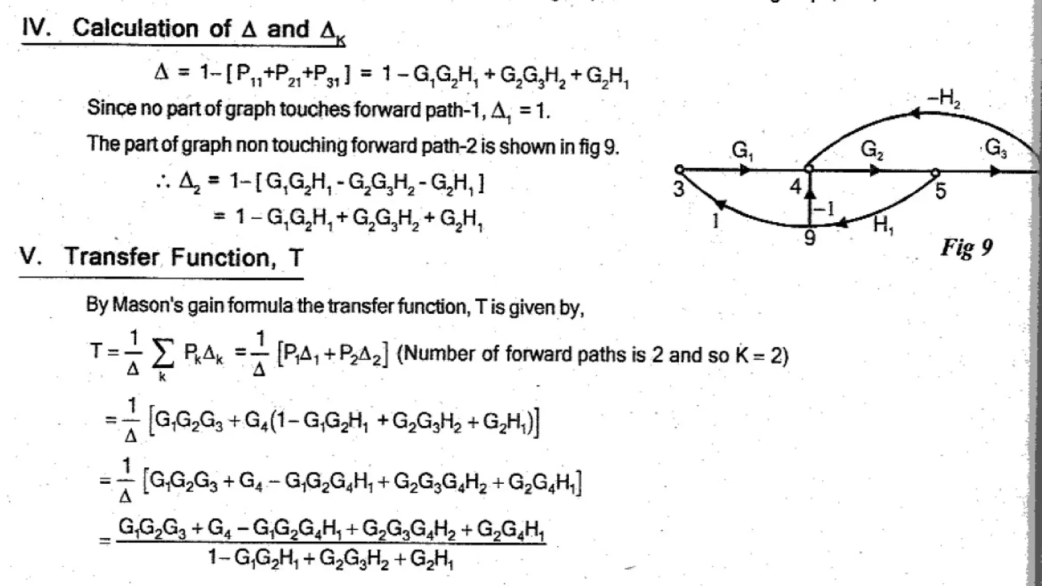
96.
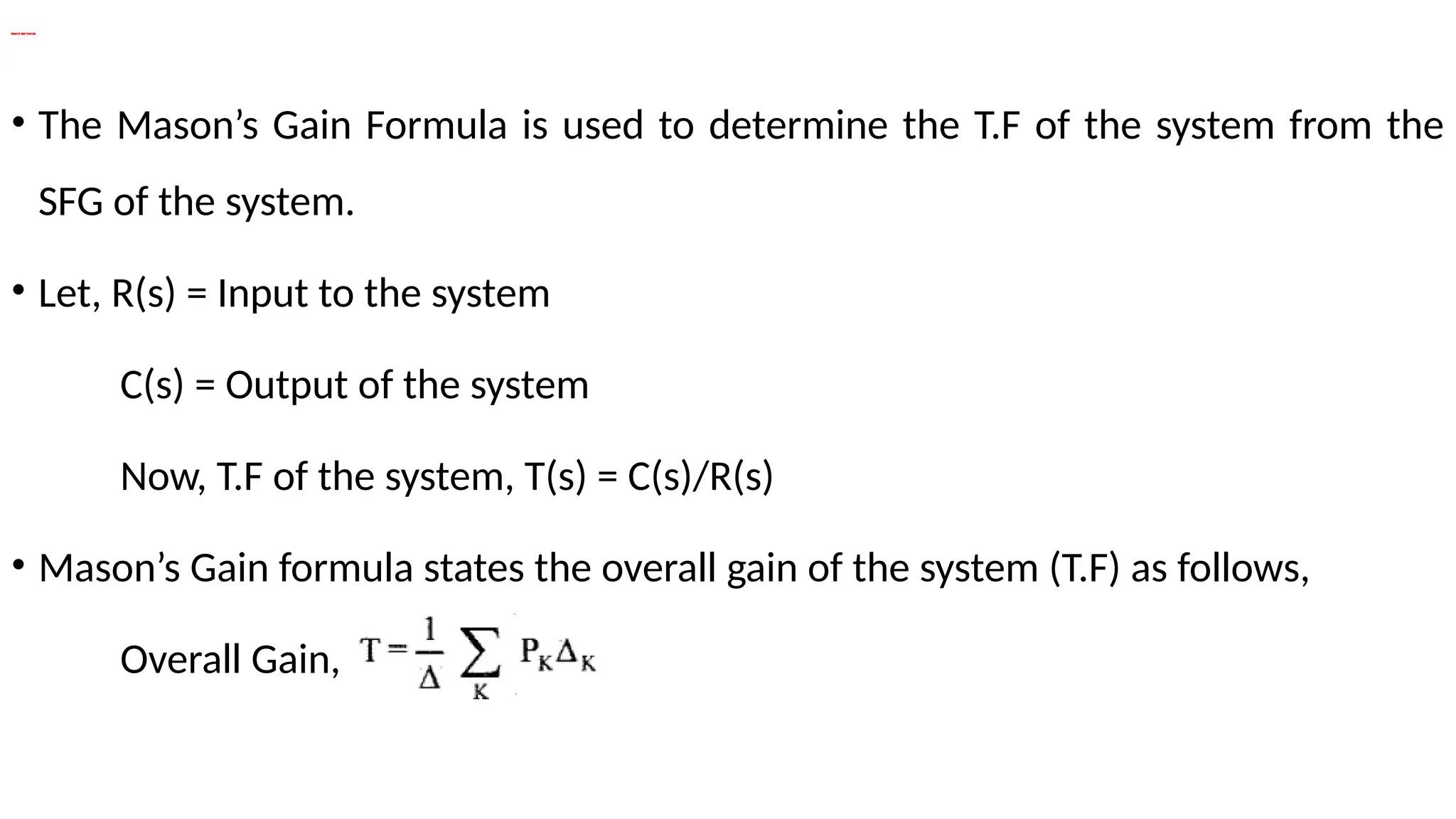
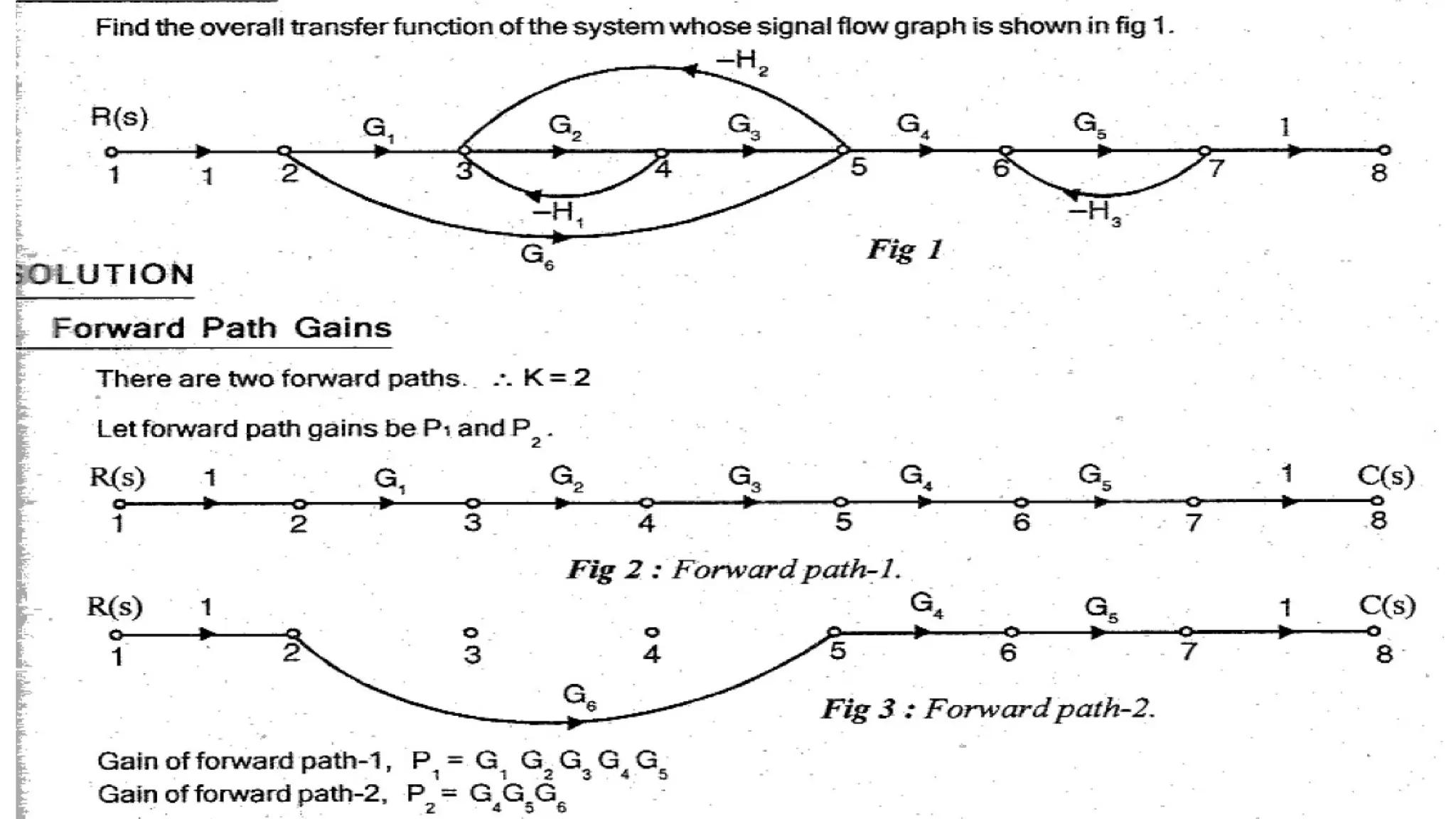
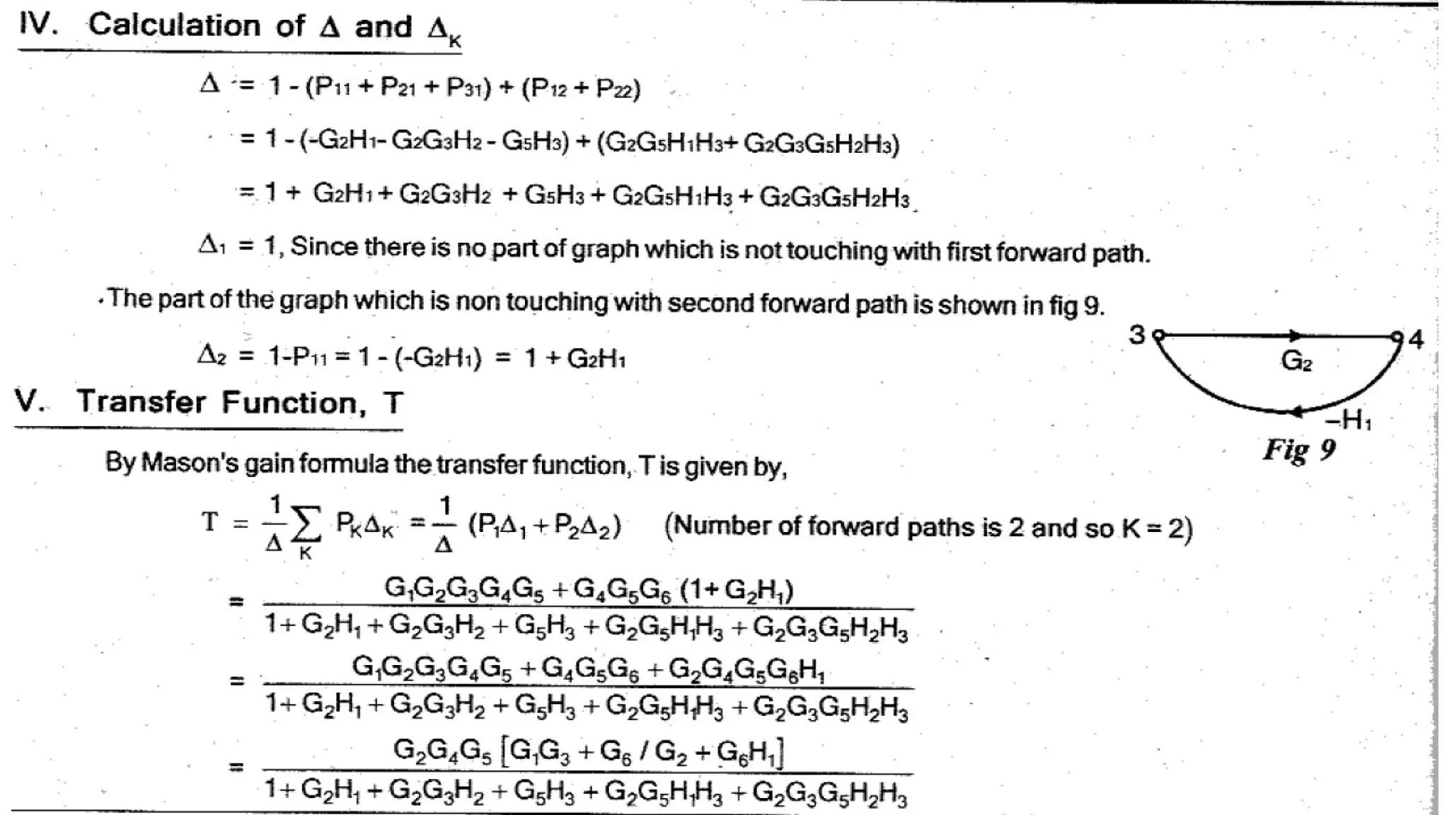
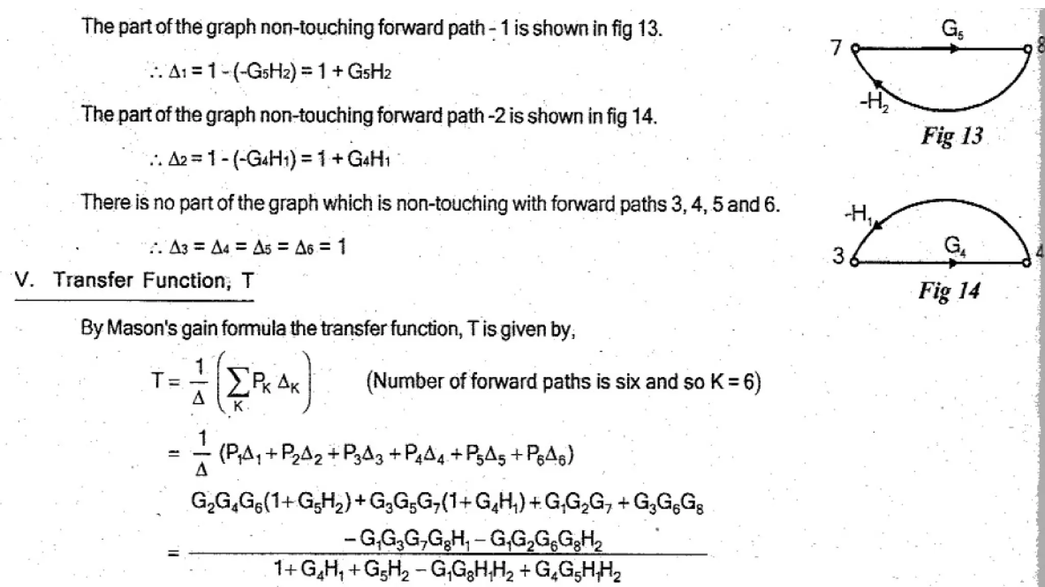
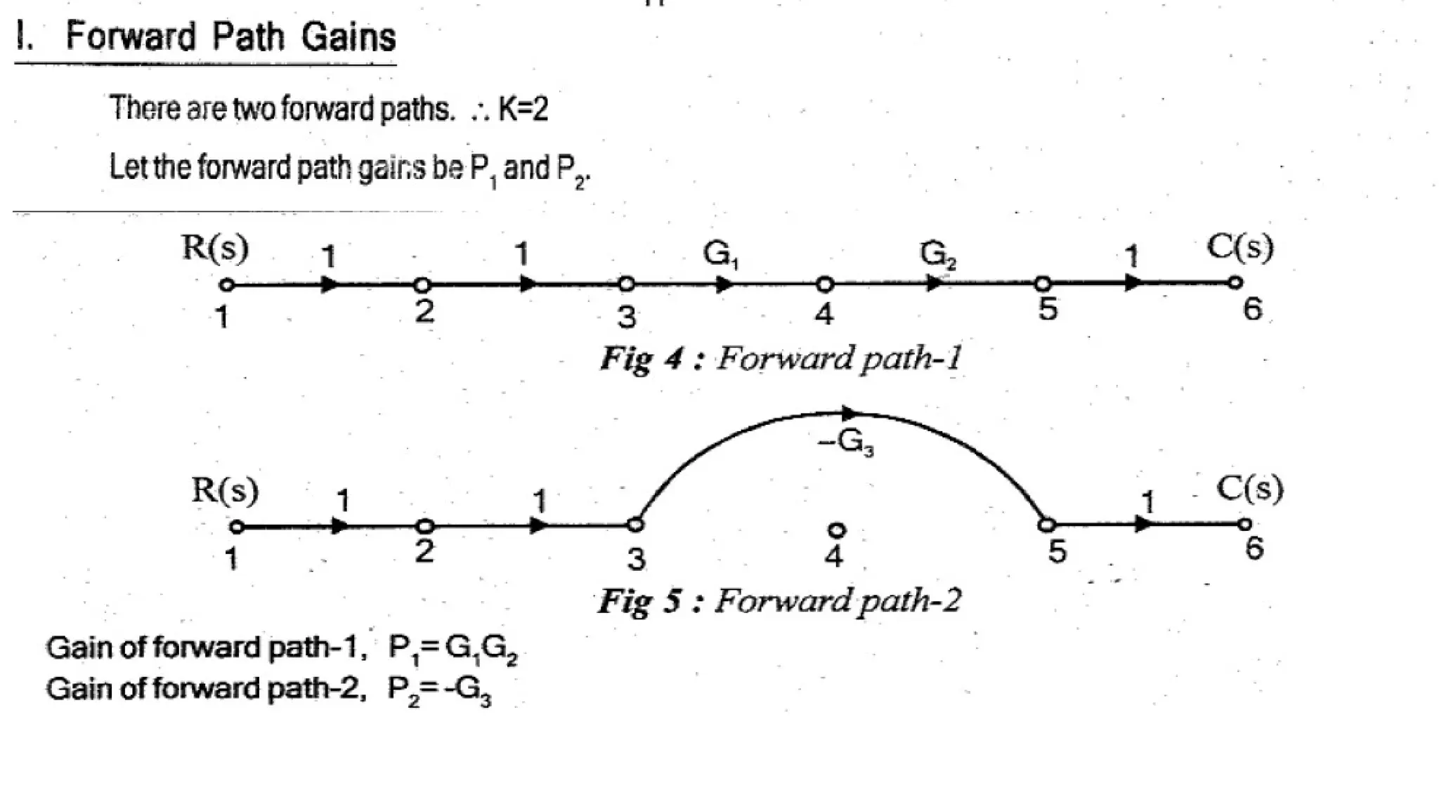
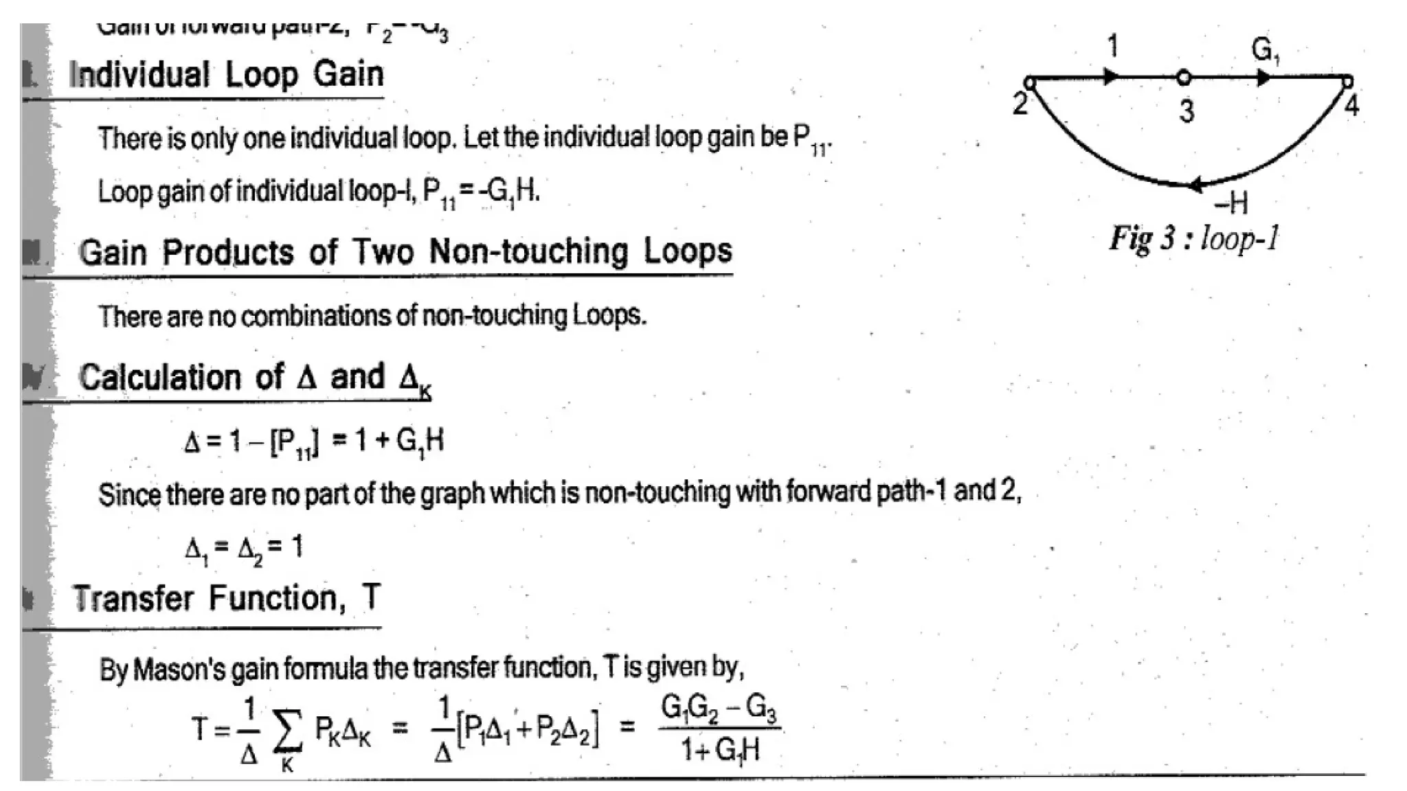
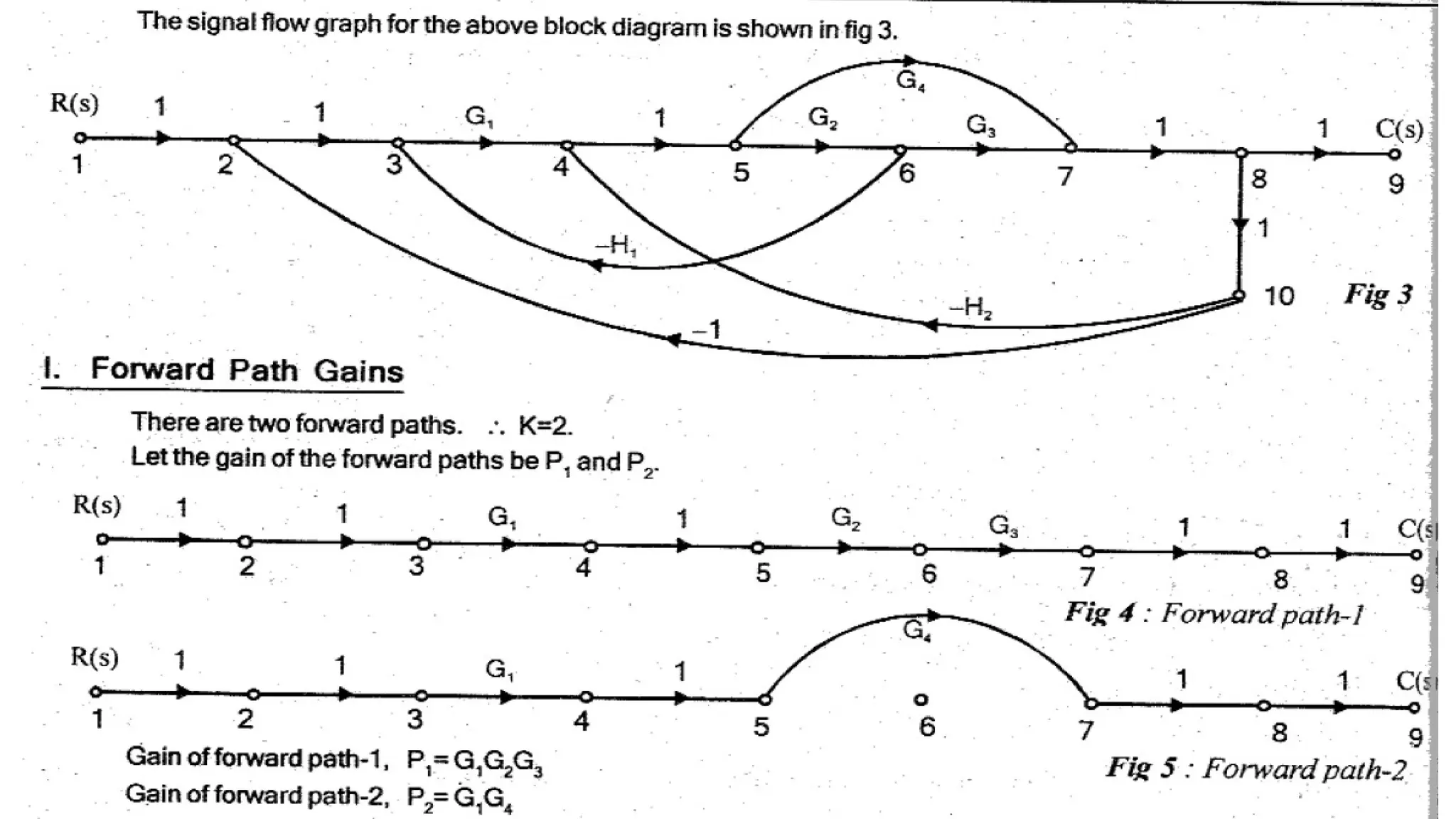
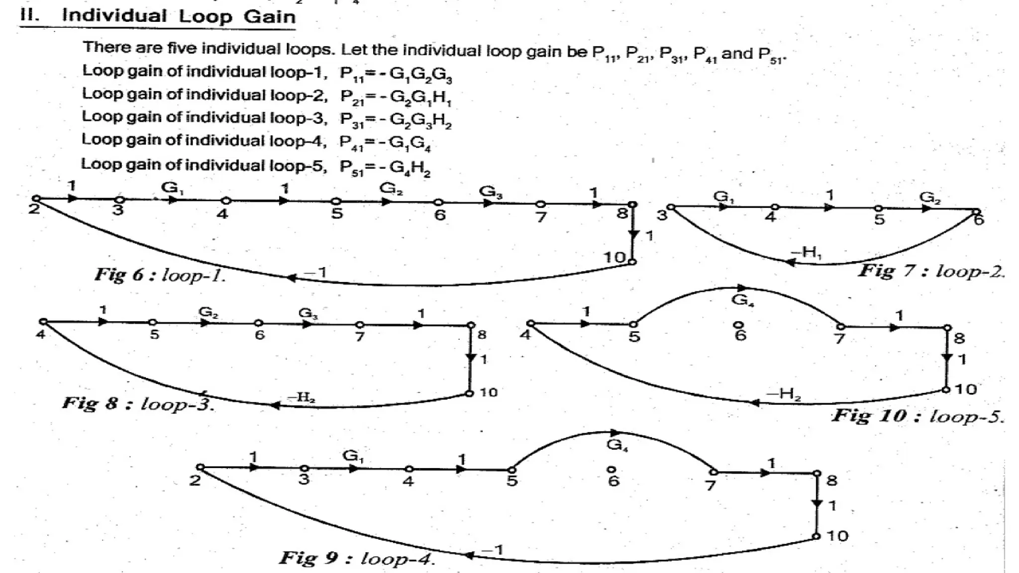
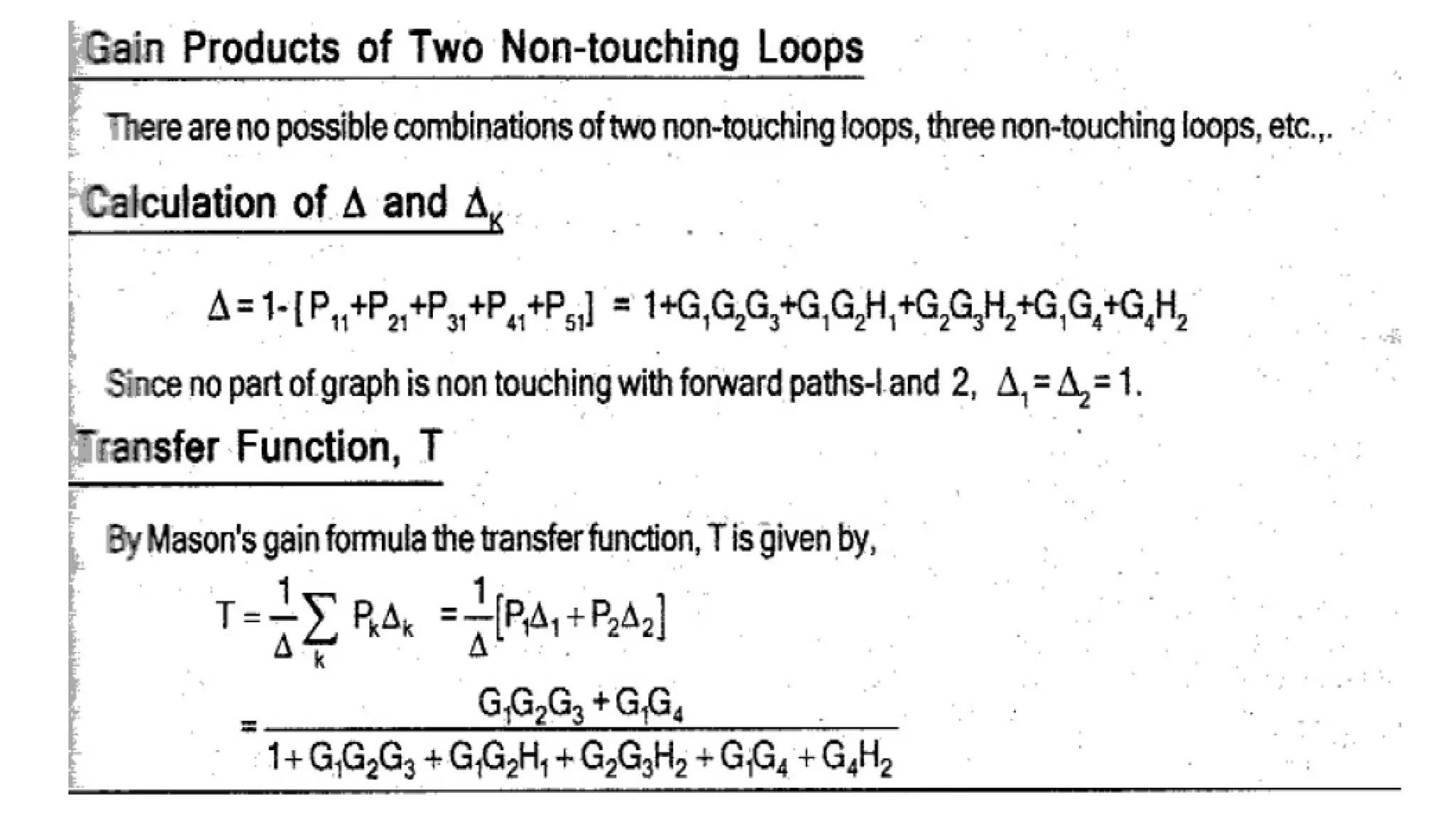
Mason’s Gain Formula
•The Mason’s Gain Formula is used to determine the T.F of the system from the
SFG of the system.
• Let, R(s) = Input to the system
C(s) = Output of the system
Now, T.F of the system, T(s) = C(s)/R(s)
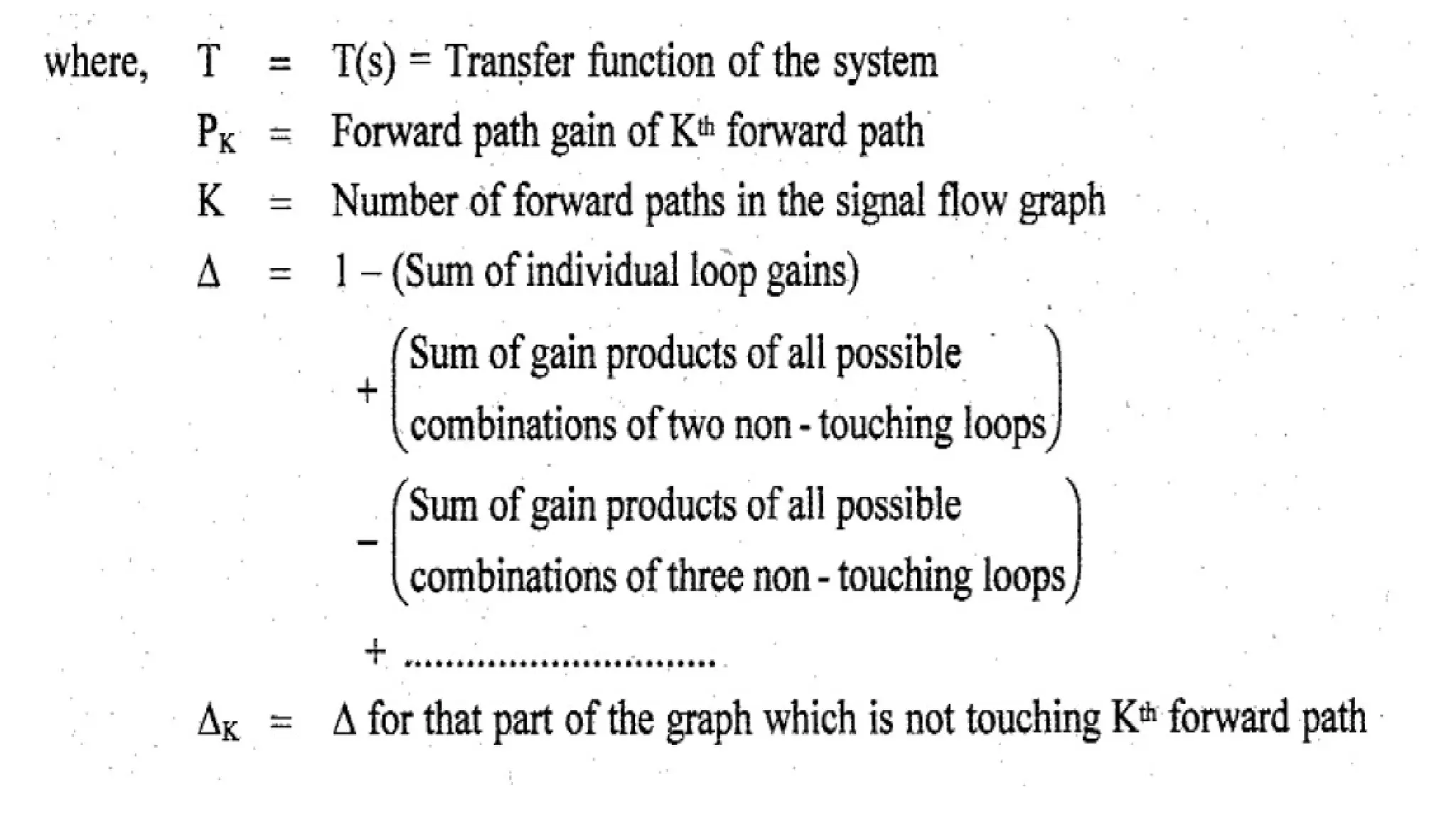
• Mason’s Gain formula states the overall gain of the system (T.F) as follows,
Overall Gain,
98.
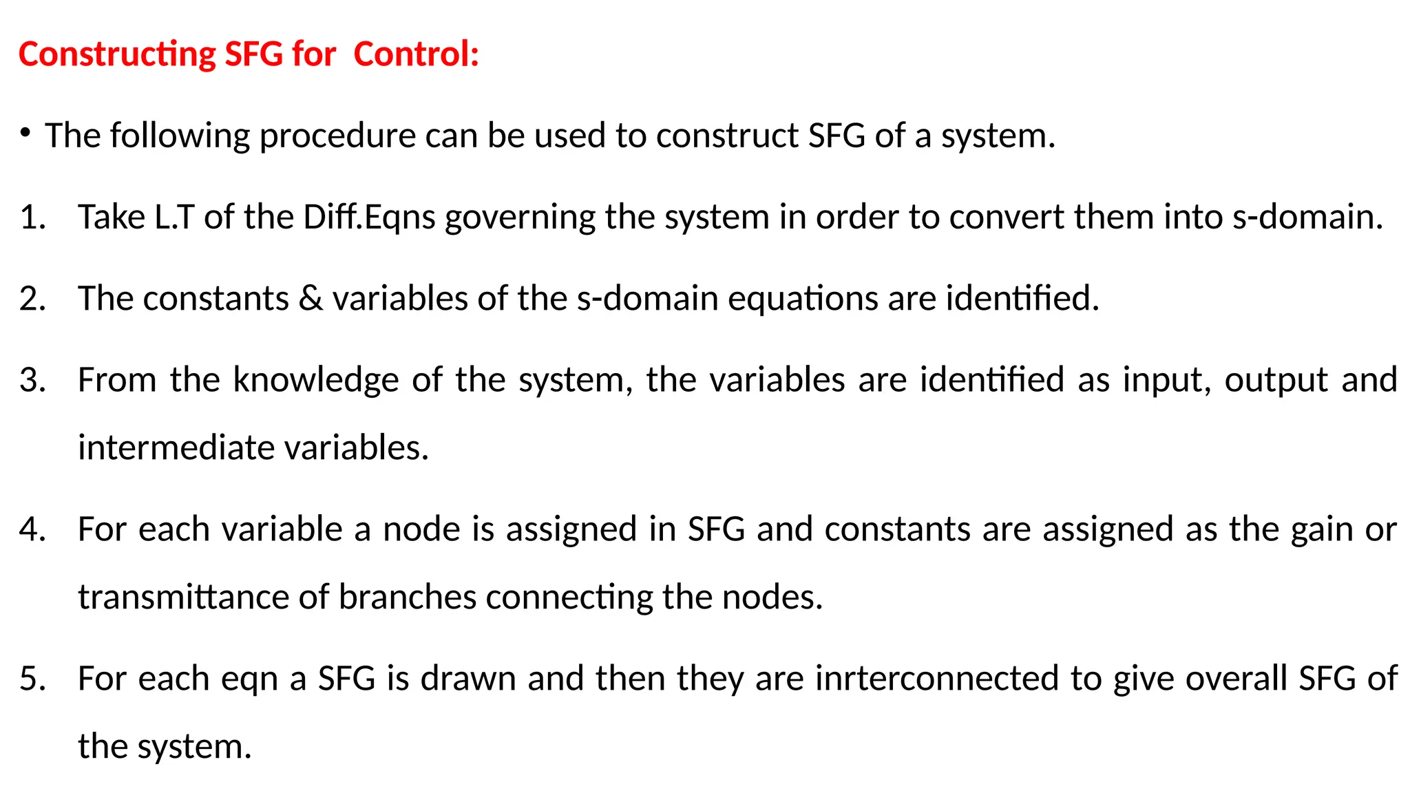
Constructing SFG forControl:
• The following procedure can be used to construct SFG of a system.
1. Take L.T of the Diff.Eqns governing the system in order to convert them into s-domain.
2. The constants & variables of the s-domain equations are identified.
3. From the knowledge of the system, the variables are identified as input, output and
intermediate variables.
4. For each variable a node is assigned in SFG and constants are assigned as the gain or
transmittance of branches connecting the nodes.
5. For each eqn a SFG is drawn and then they are inrterconnected to give overall SFG of
the system.
109.
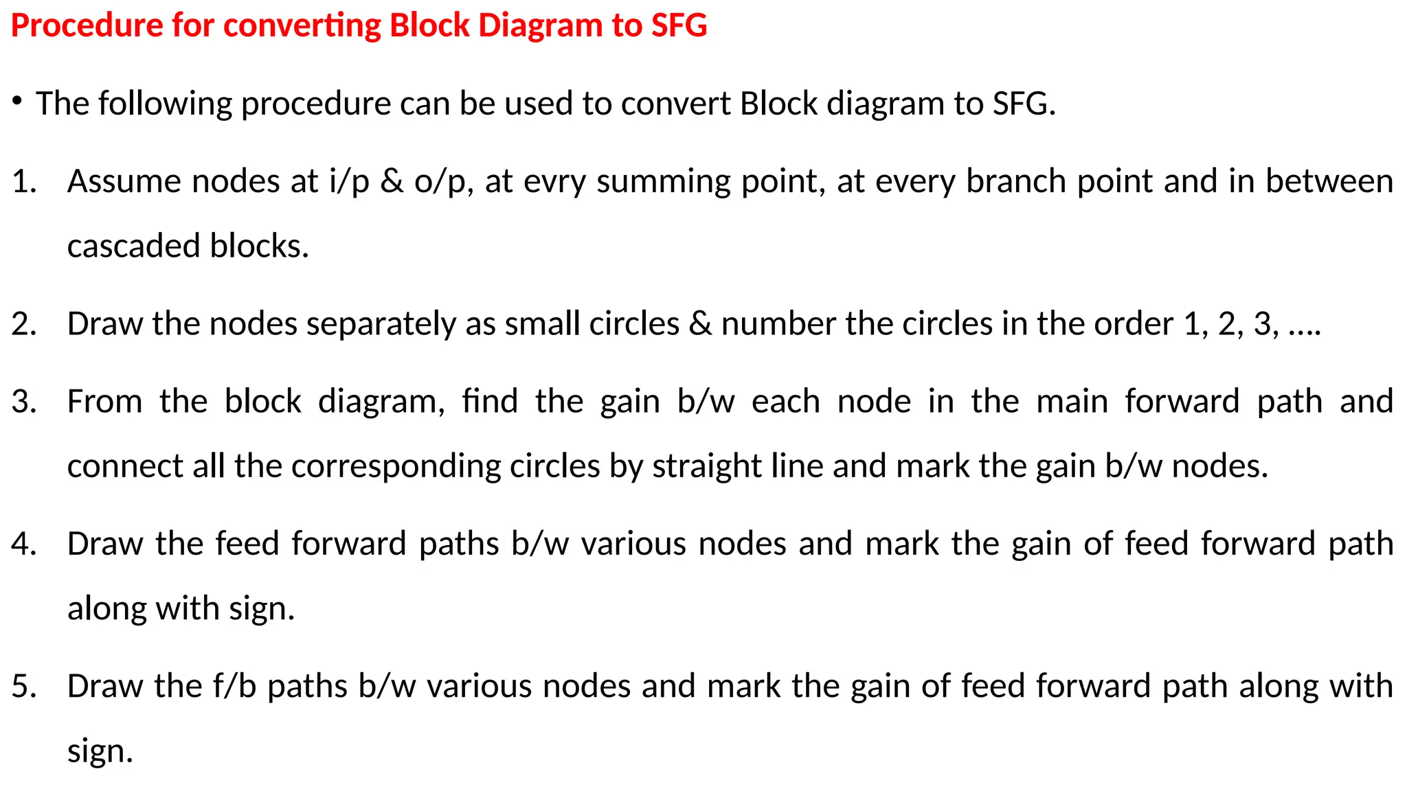
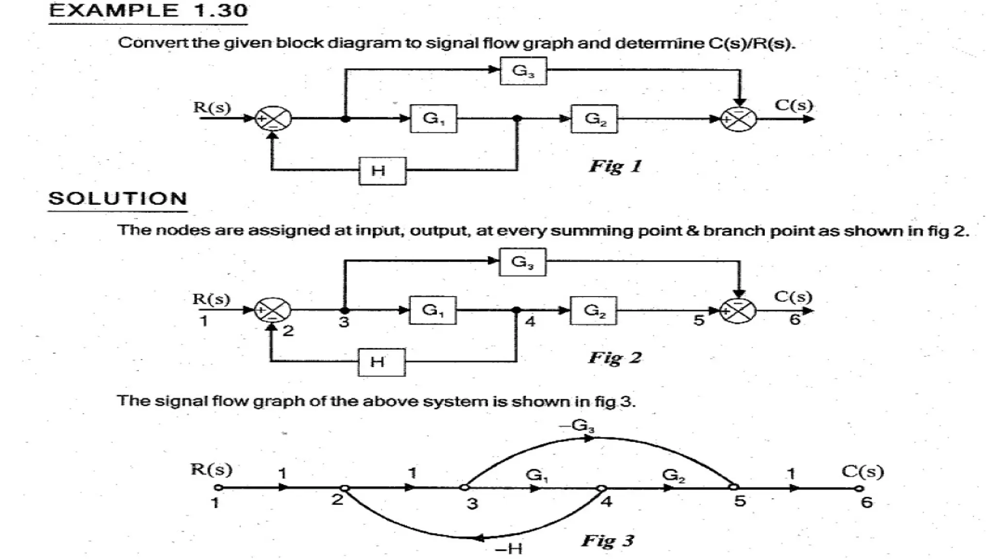
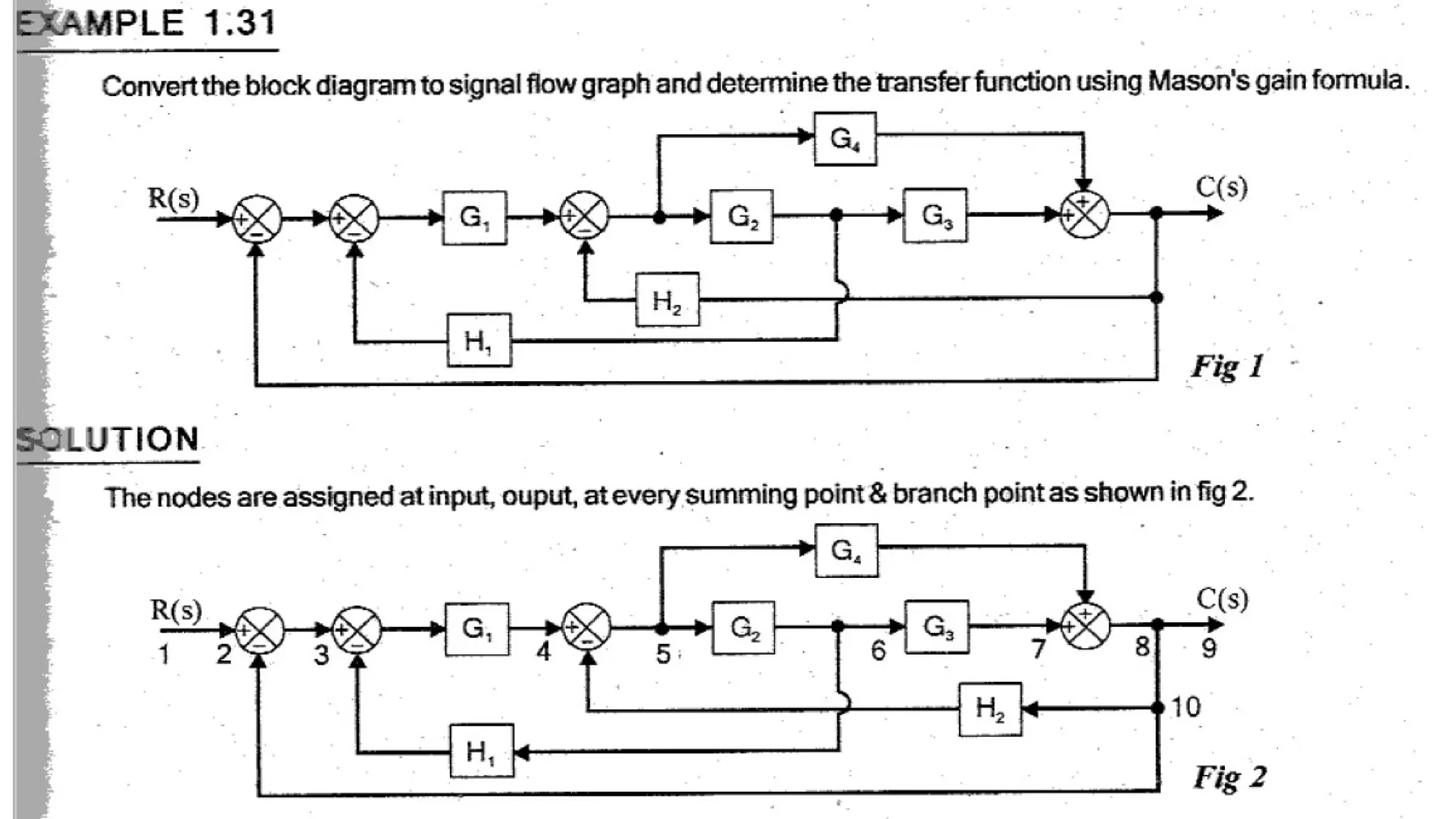
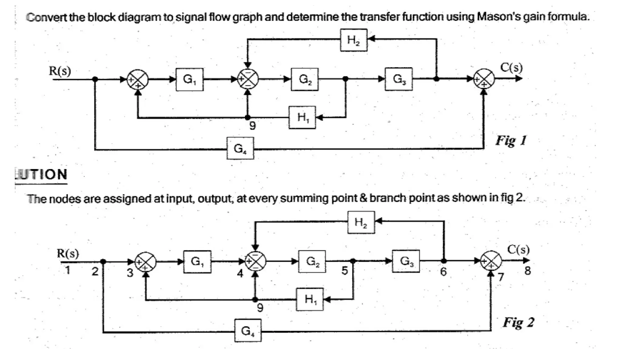
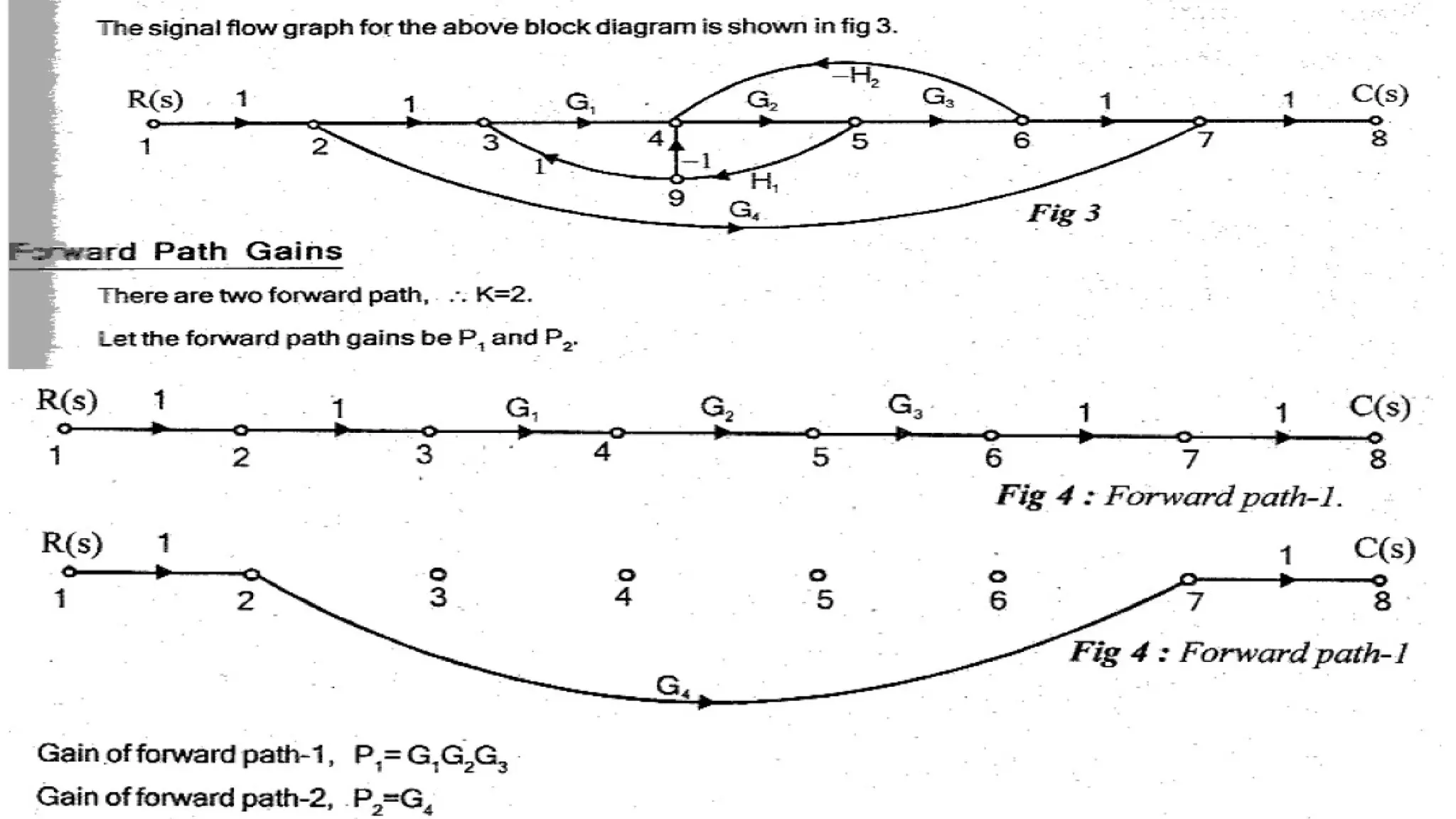
Procedure for convertingBlock Diagram to SFG
• The following procedure can be used to convert Block diagram to SFG.
1. Assume nodes at i/p & o/p, at evry summing point, at every branch point and in between
cascaded blocks.
2. Draw the nodes separately as small circles & number the circles in the order 1, 2, 3, ….
3. From the block diagram, find the gain b/w each node in the main forward path and
connect all the corresponding circles by straight line and mark the gain b/w nodes.
4. Draw the feed forward paths b/w various nodes and mark the gain of feed forward path
along with sign.
5. Draw the f/b paths b/w various nodes and mark the gain of feed forward path along with
sign.
121.
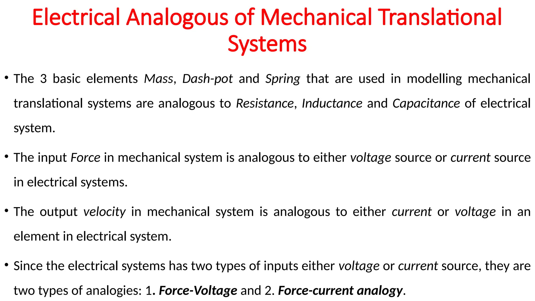
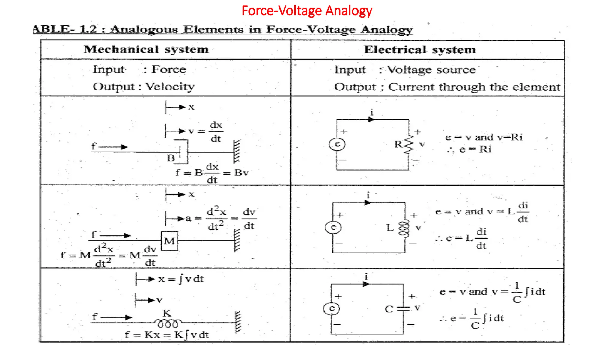
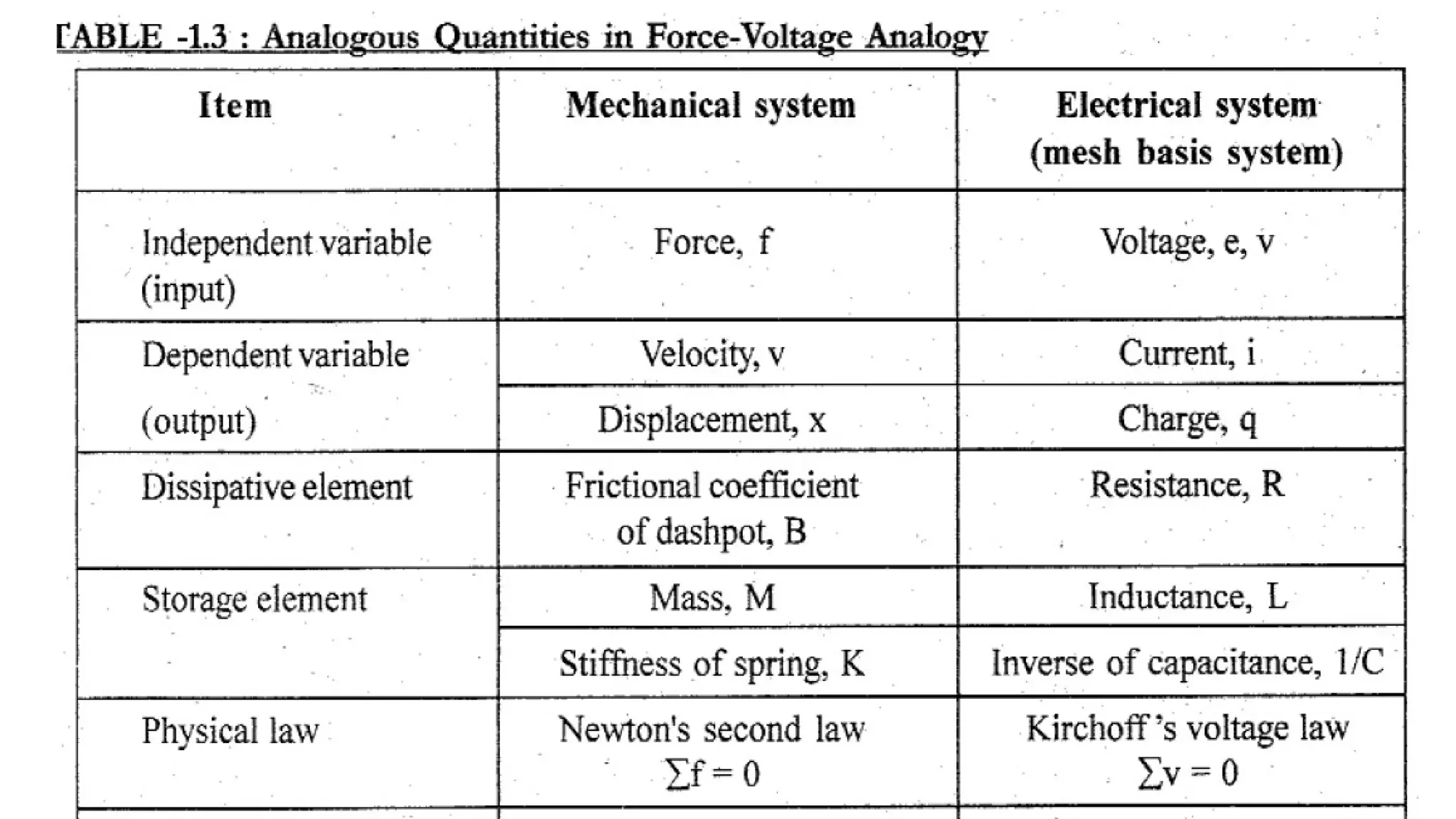
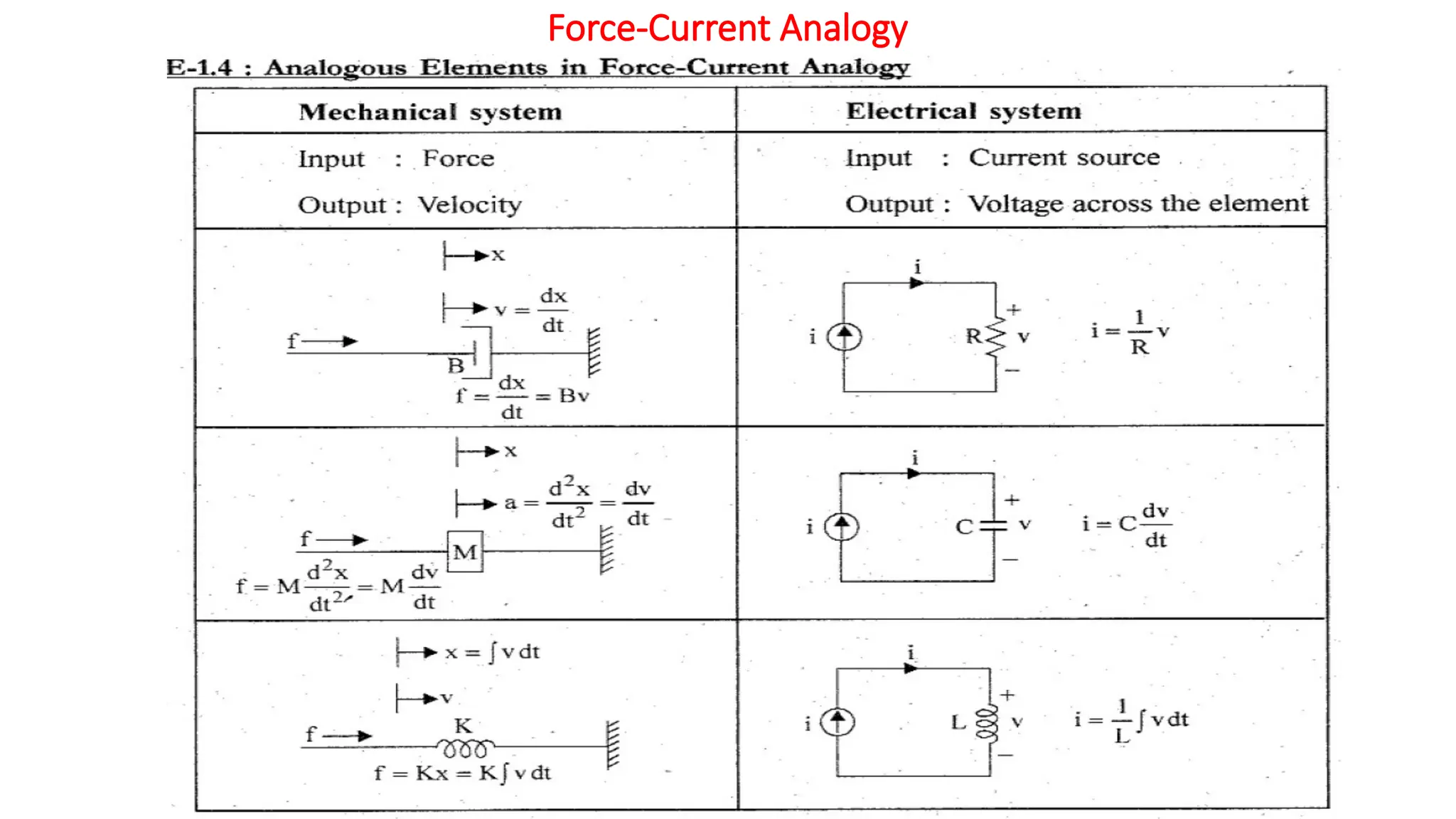
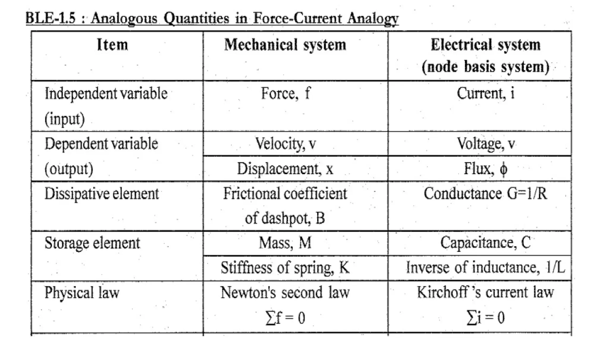
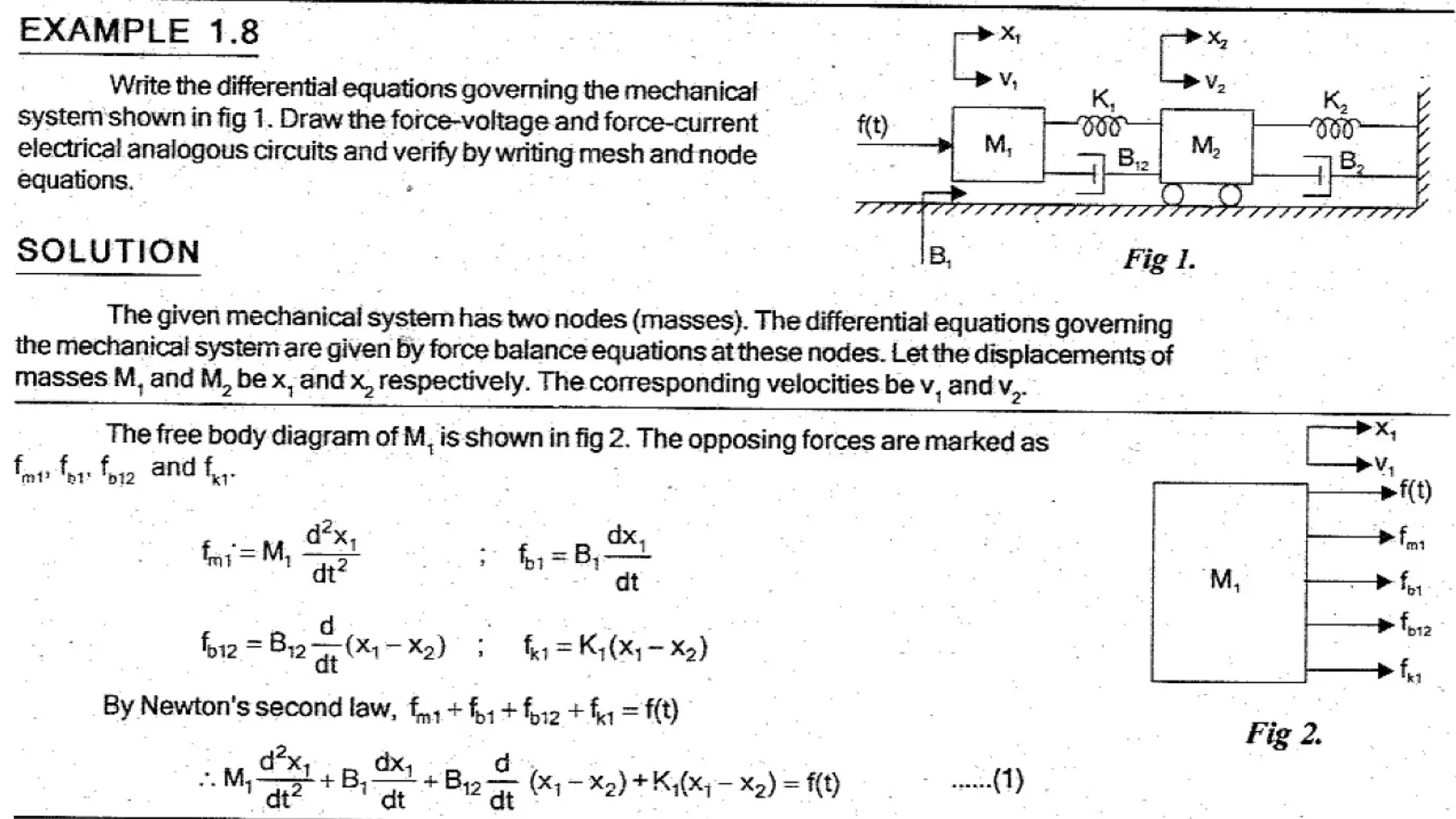
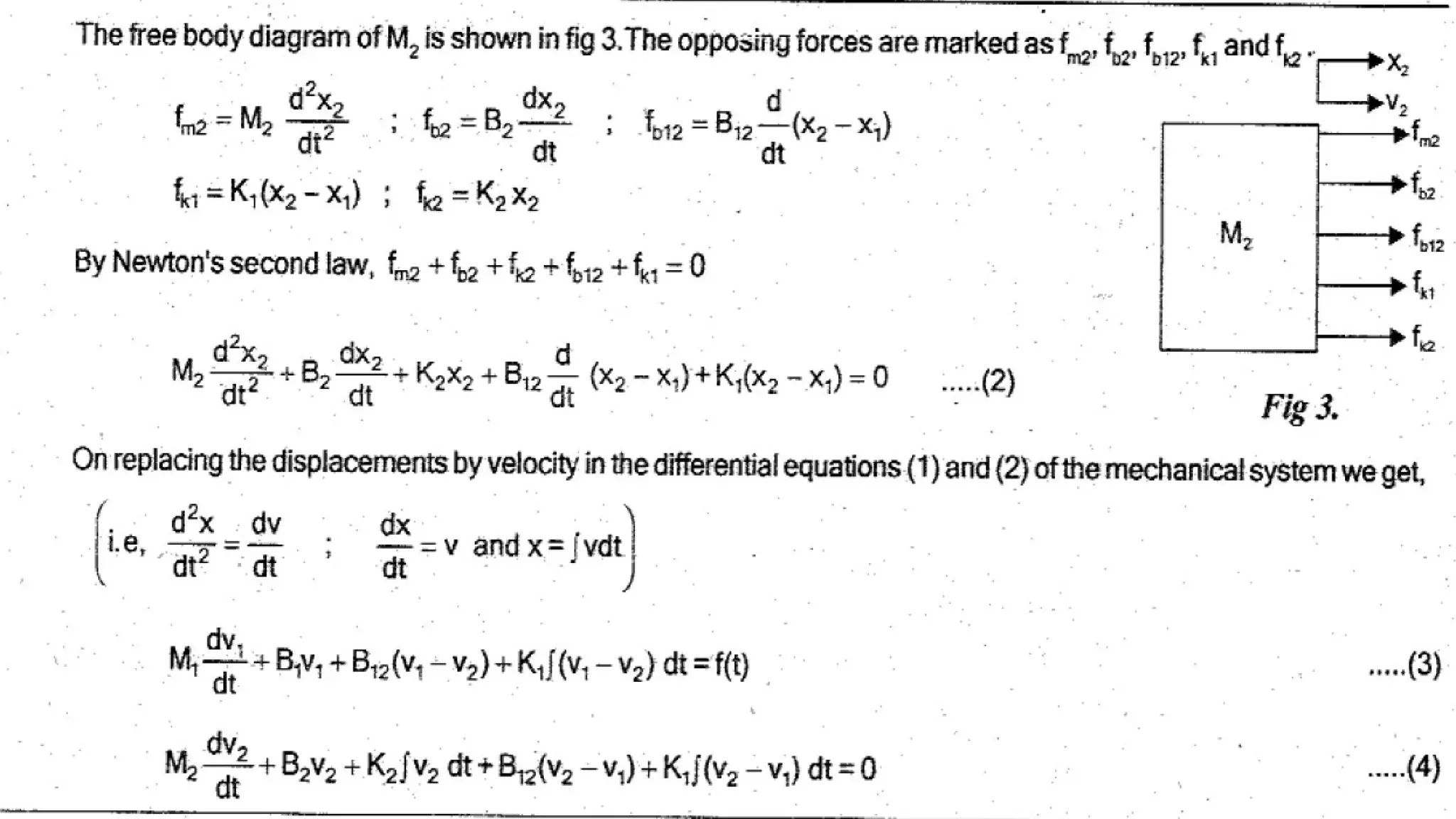
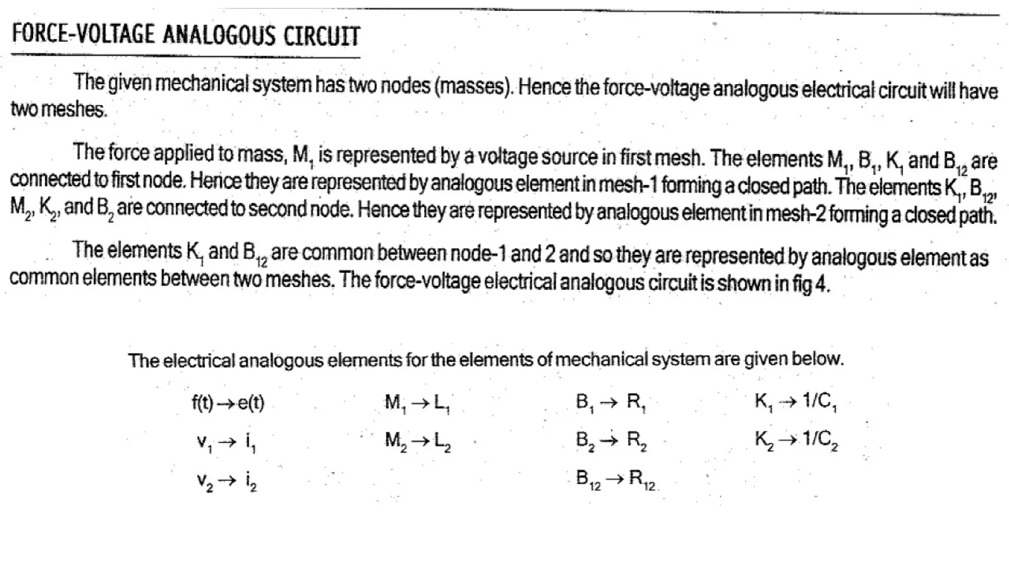
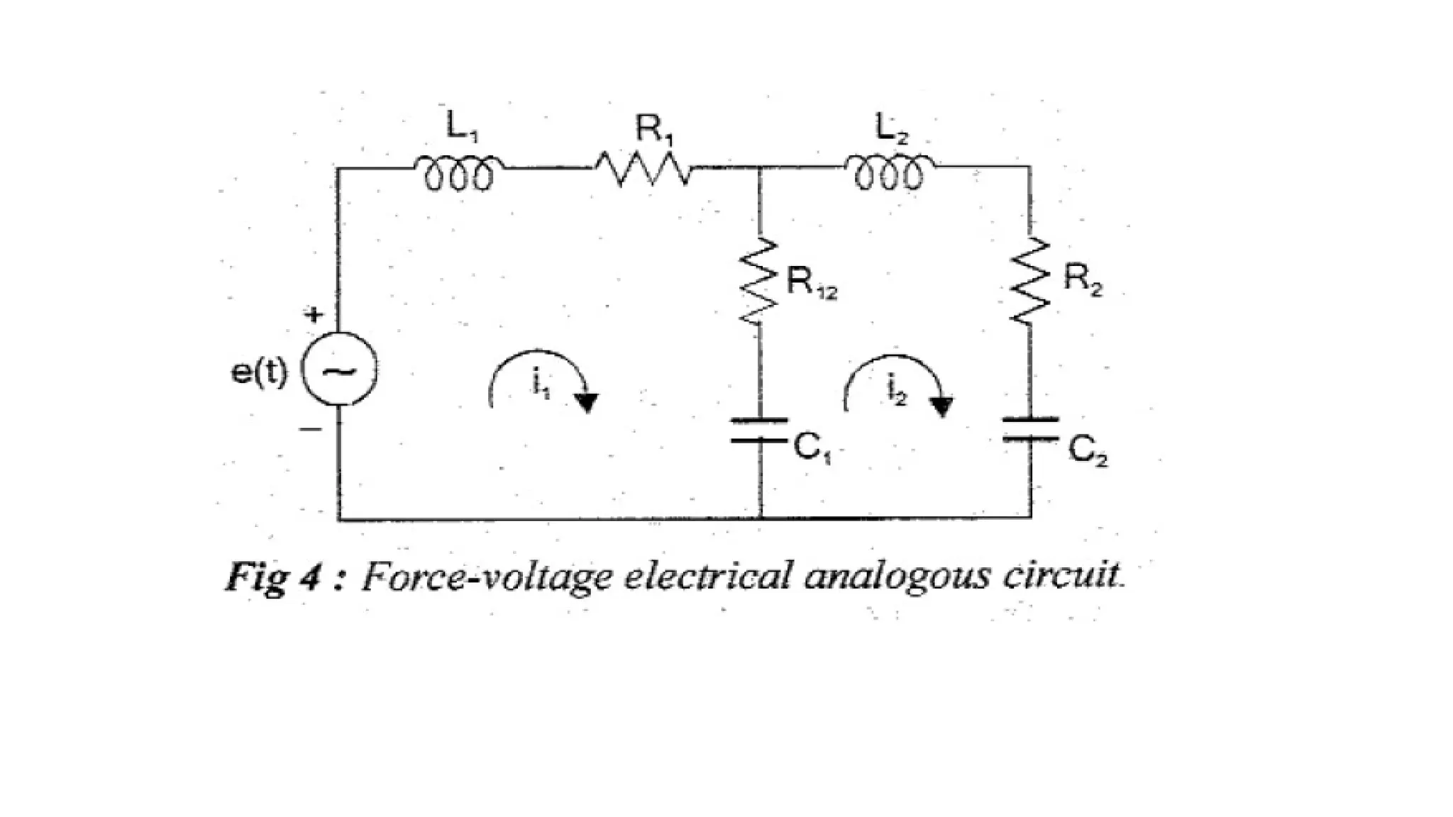
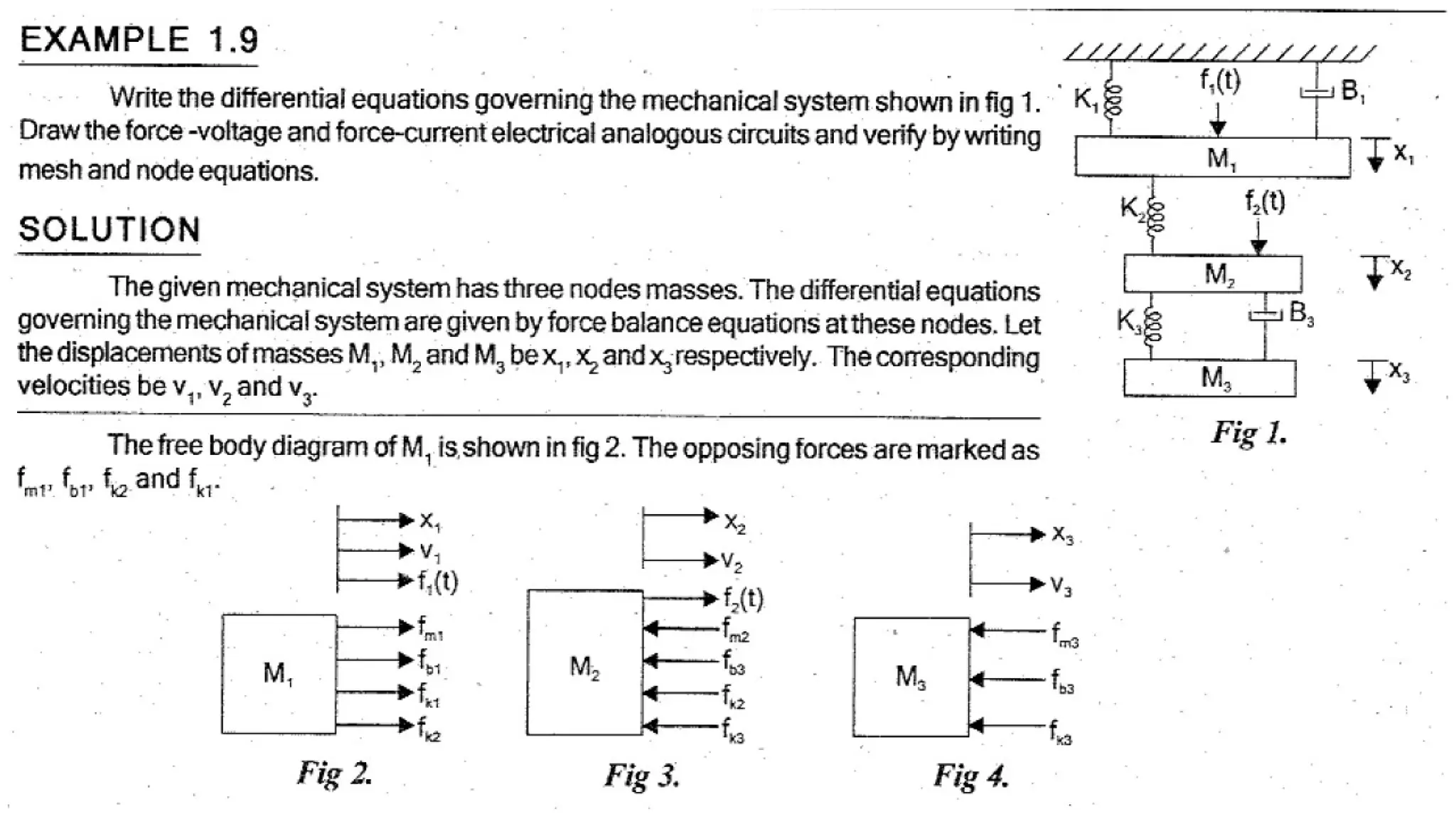
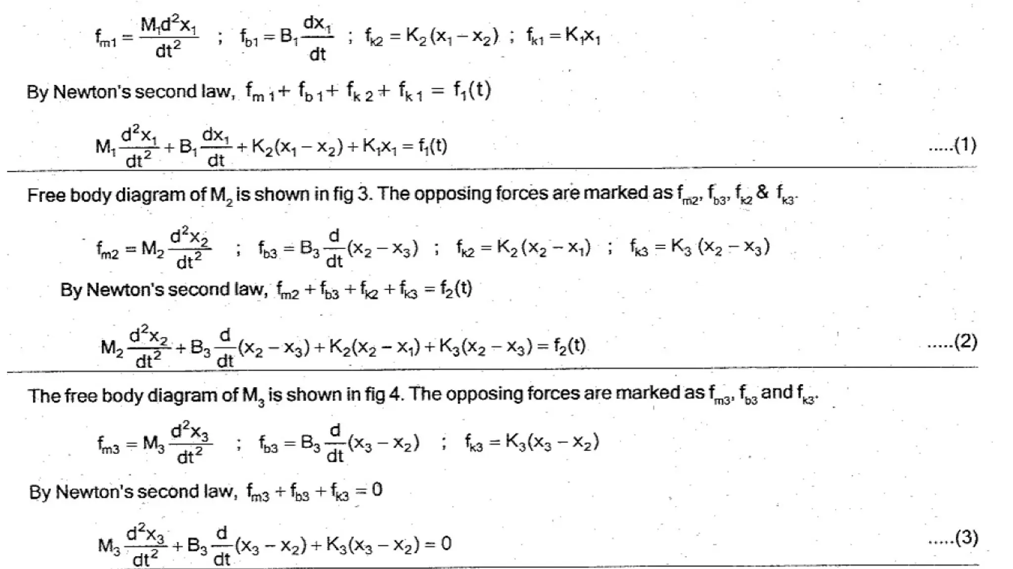
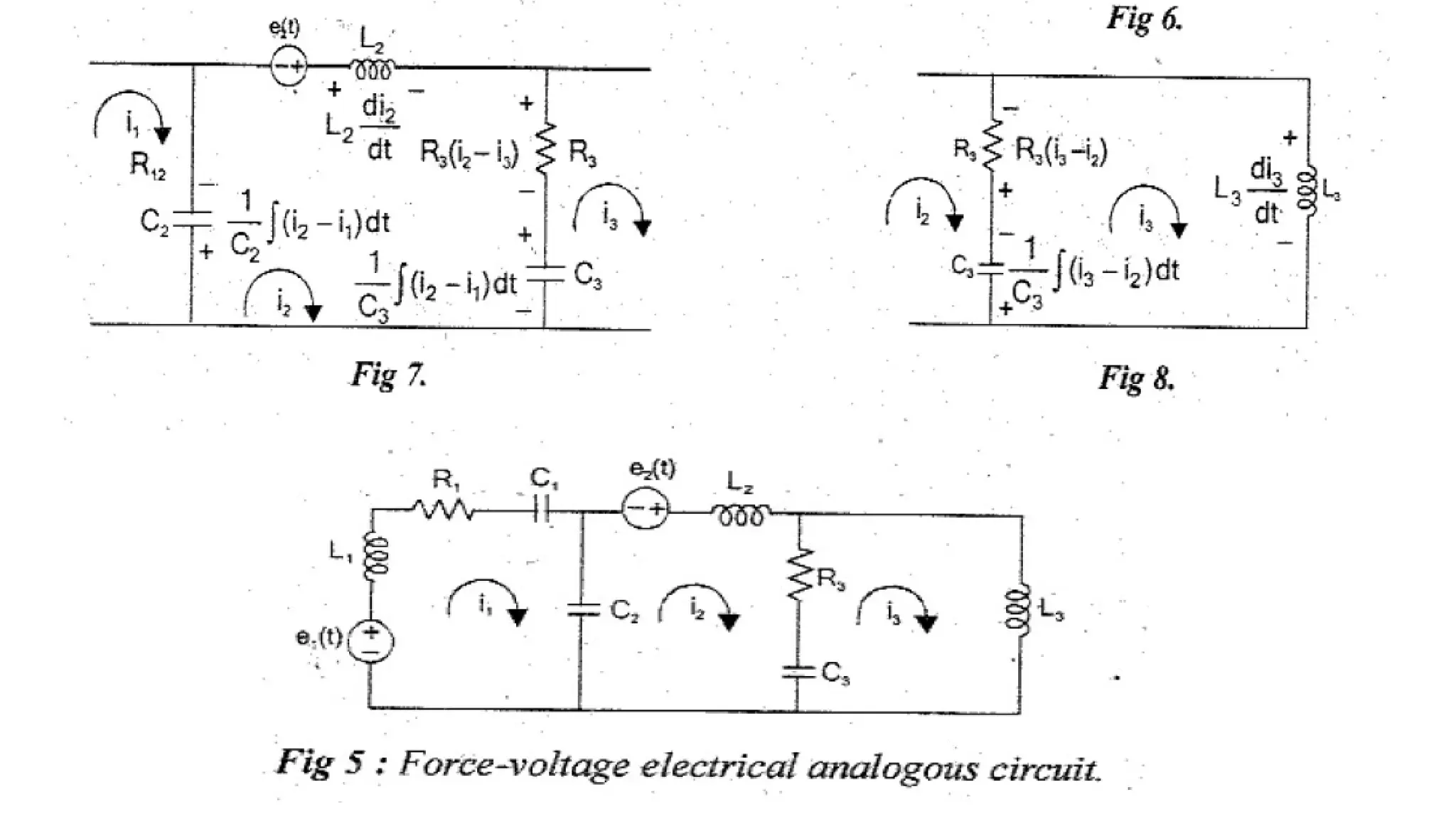
Electrical Analogous ofMechanical Translational
Systems
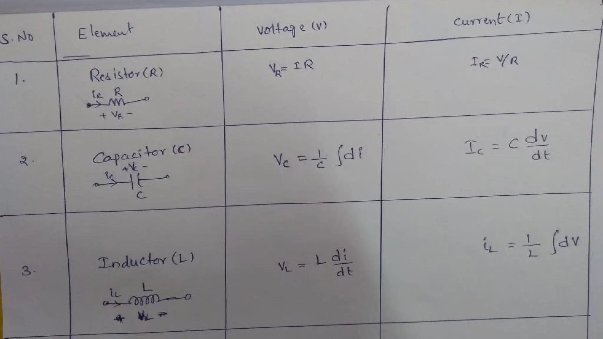
• The 3 basic elements Mass, Dash-pot and Spring that are used in modelling mechanical
translational systems are analogous to Resistance, Inductance and Capacitance of electrical
system.
• The input Force in mechanical system is analogous to either voltage source or current source
in electrical systems.
• The output velocity in mechanical system is analogous to either current or voltage in an
element in electrical system.
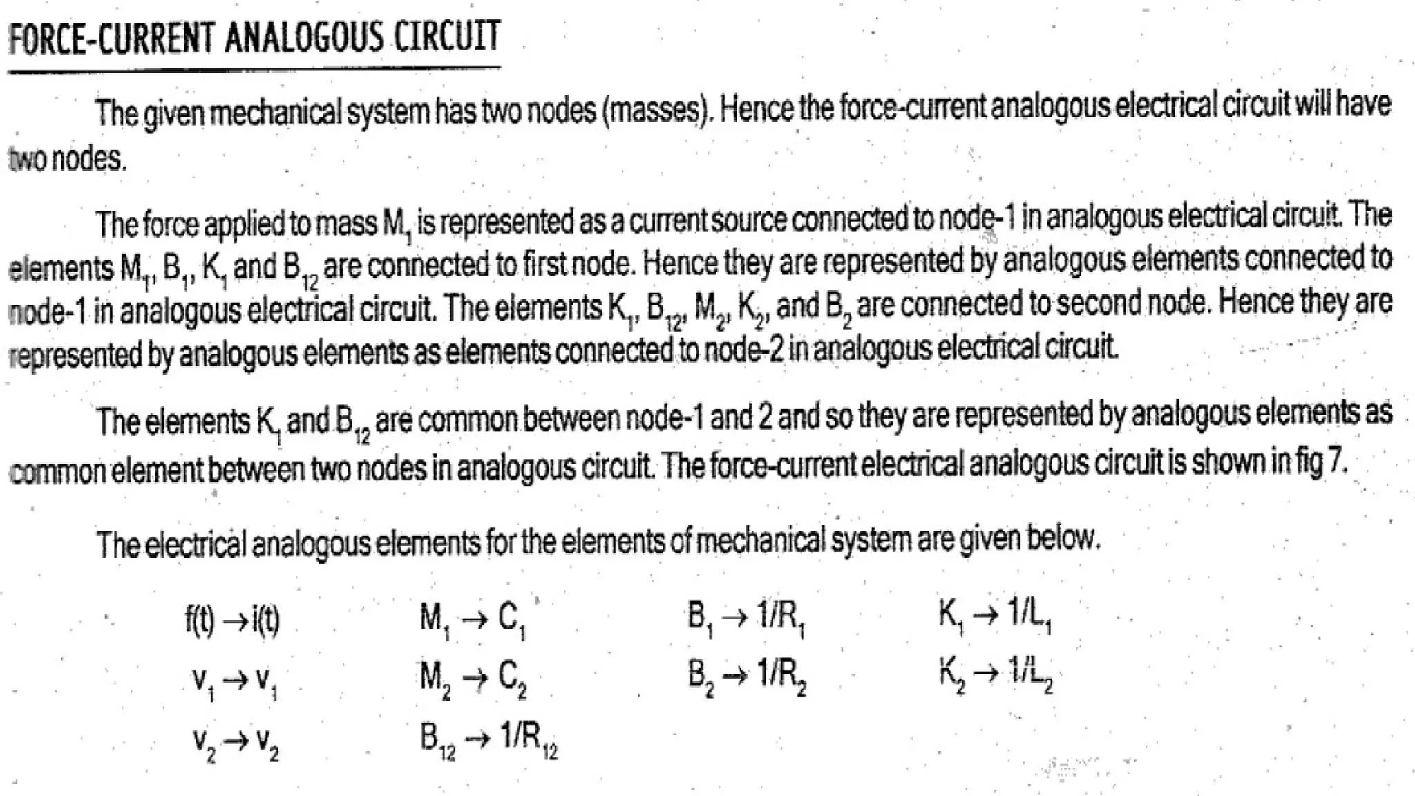
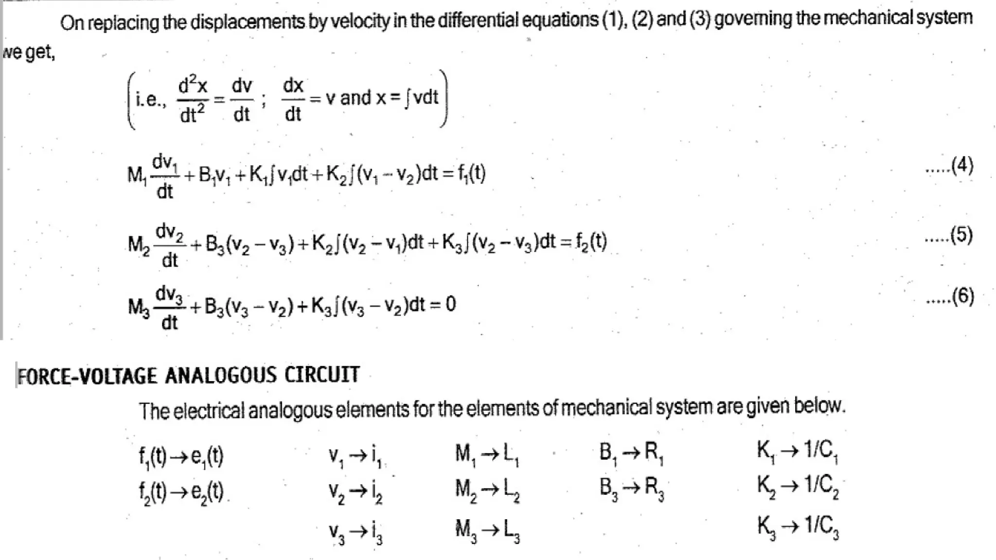
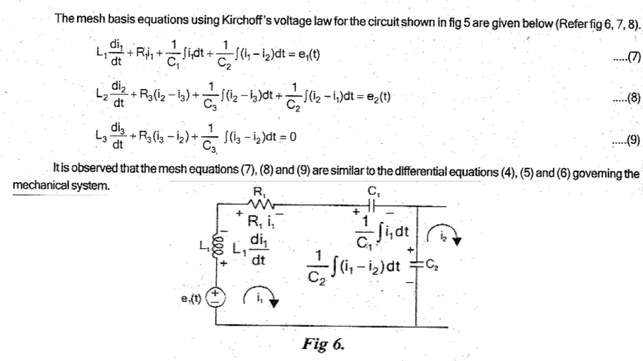
• Since the electrical systems has two types of inputs either voltage or current source, they are
two types of analogies: 1. Force-Voltage and 2. Force-current analogy.
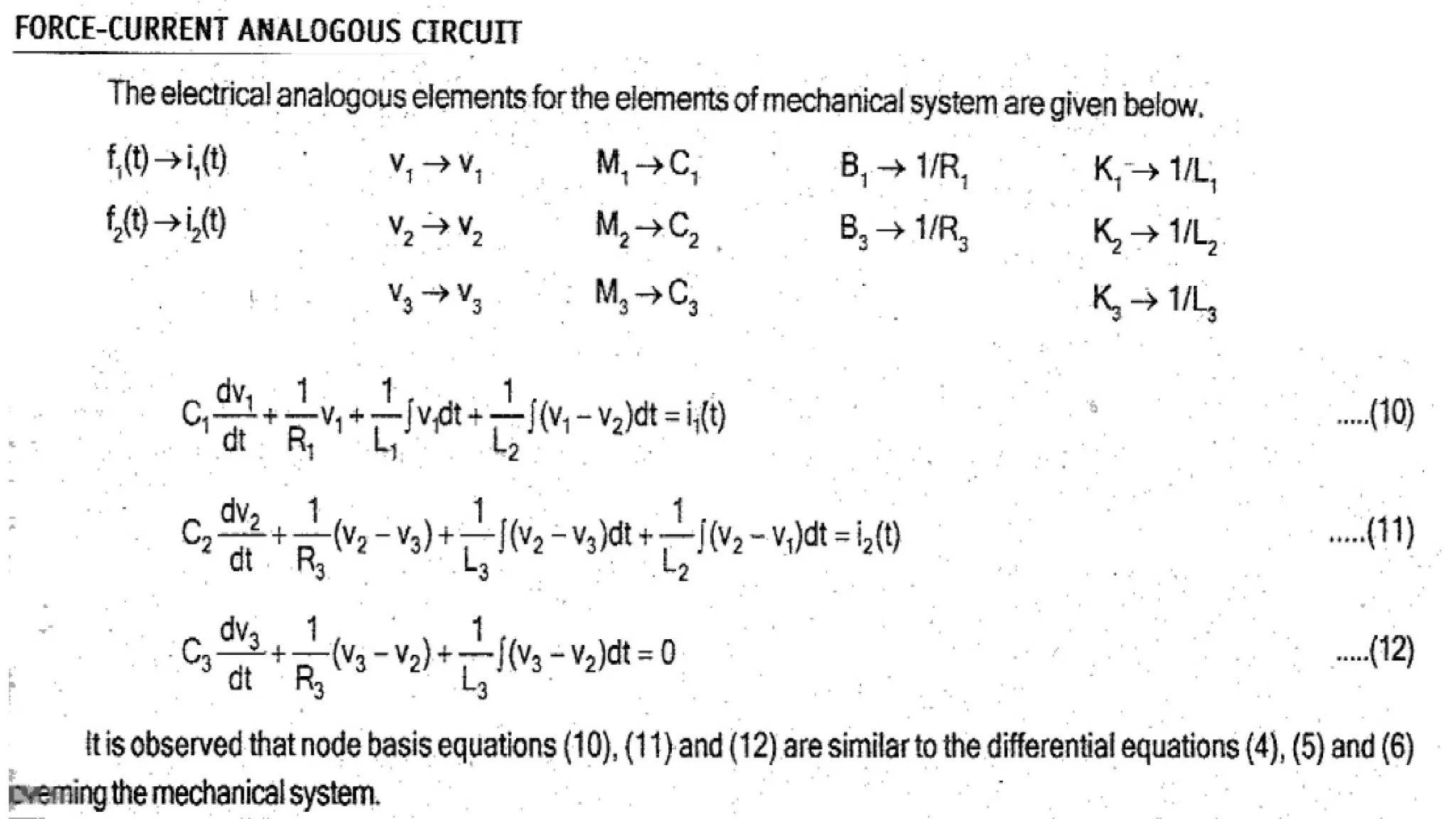
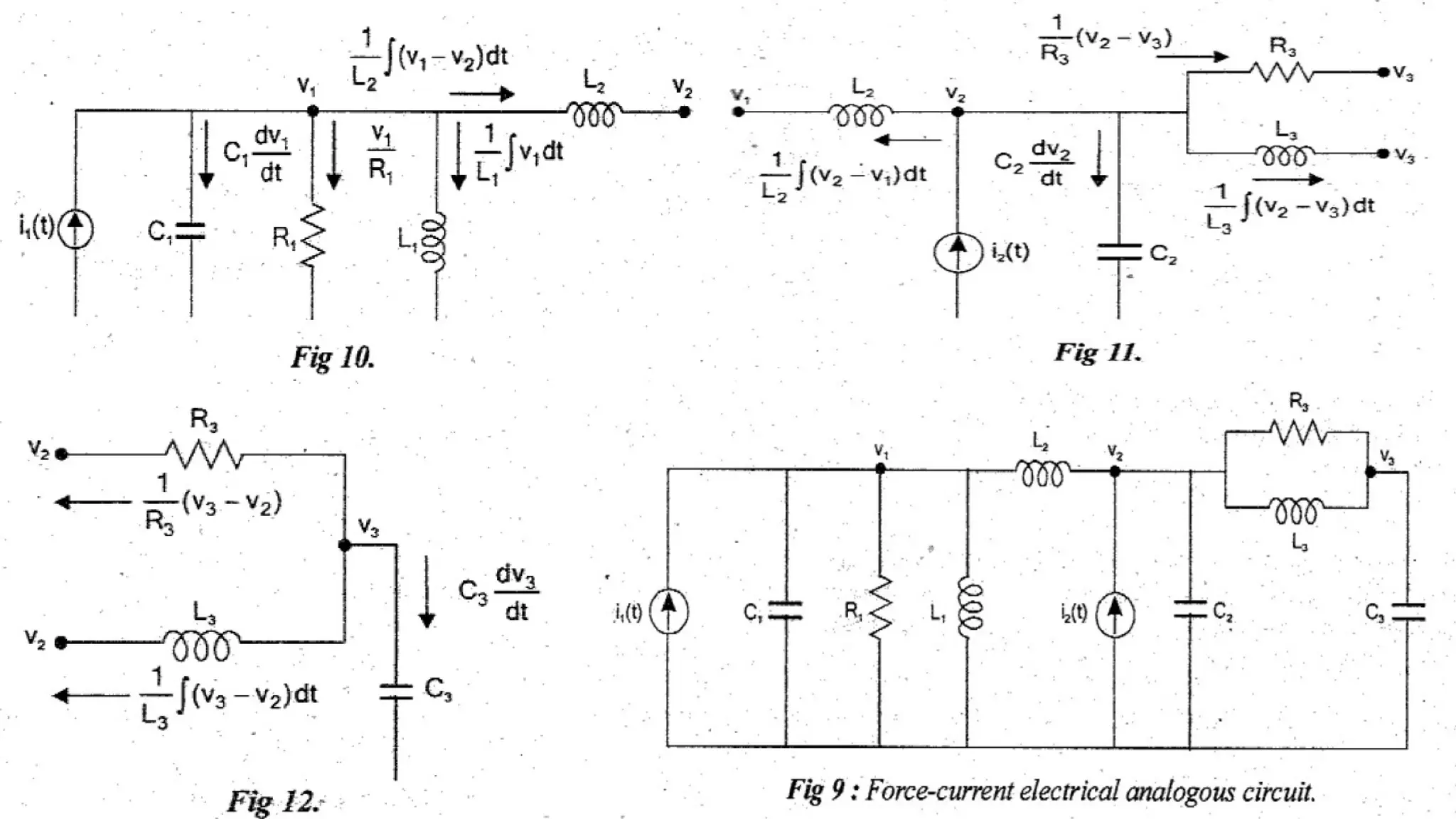
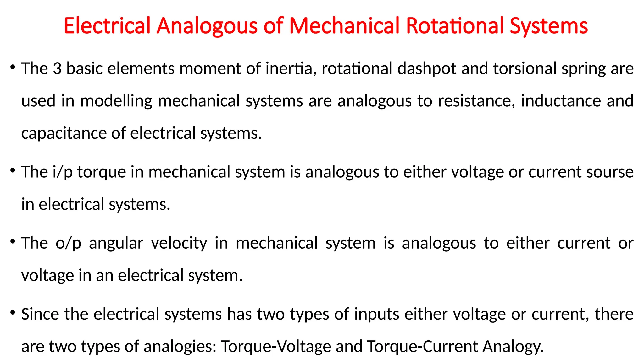
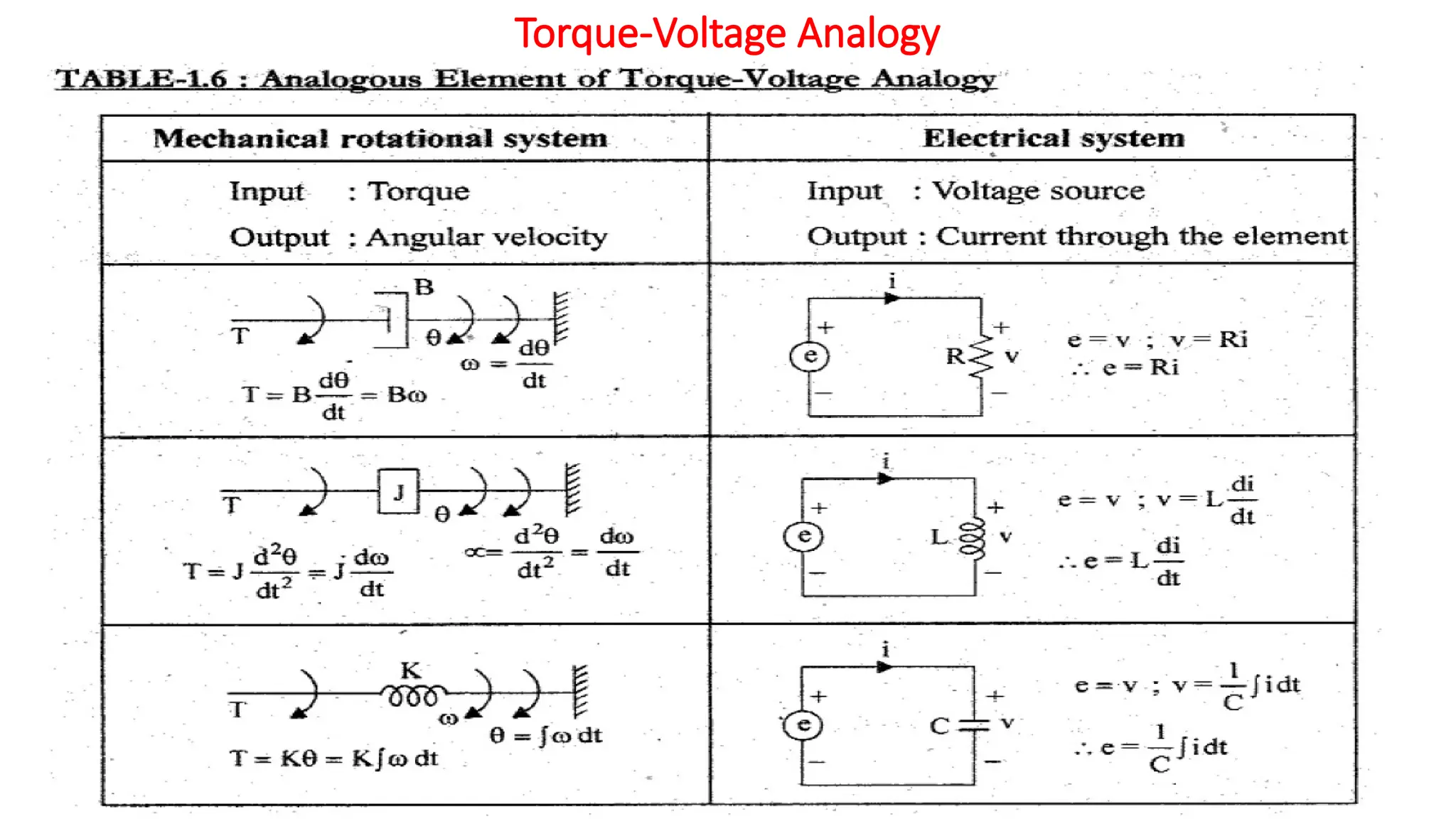
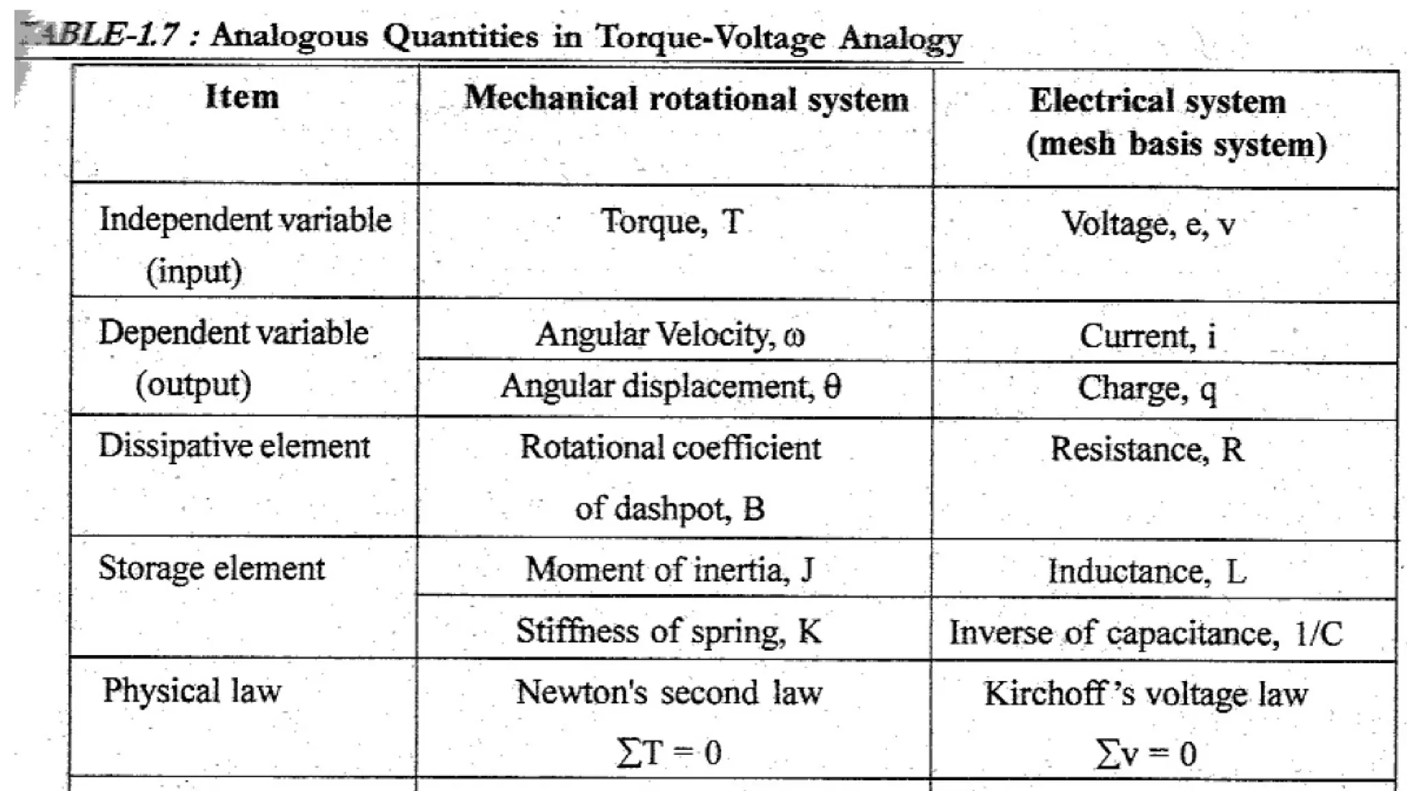
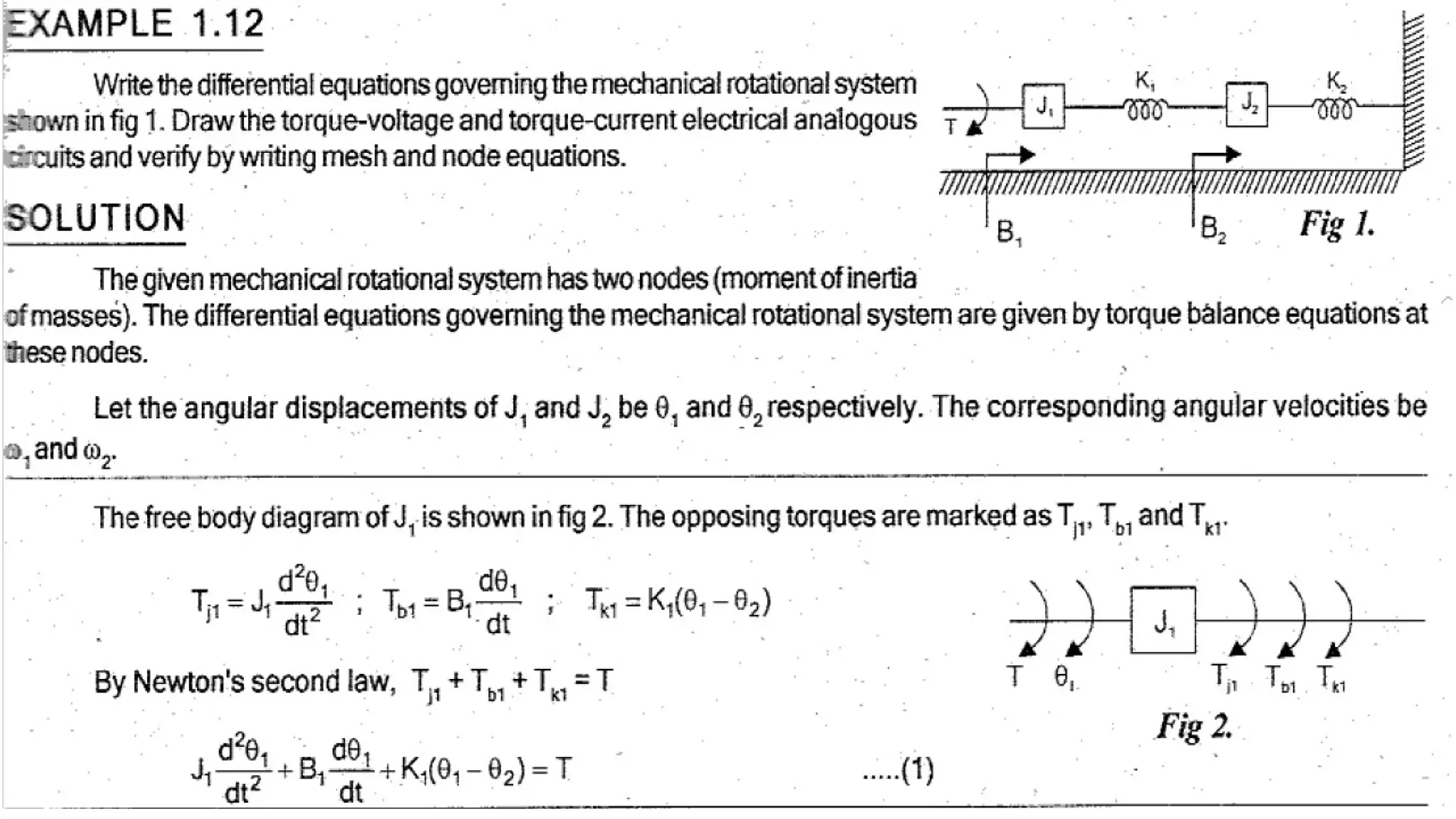
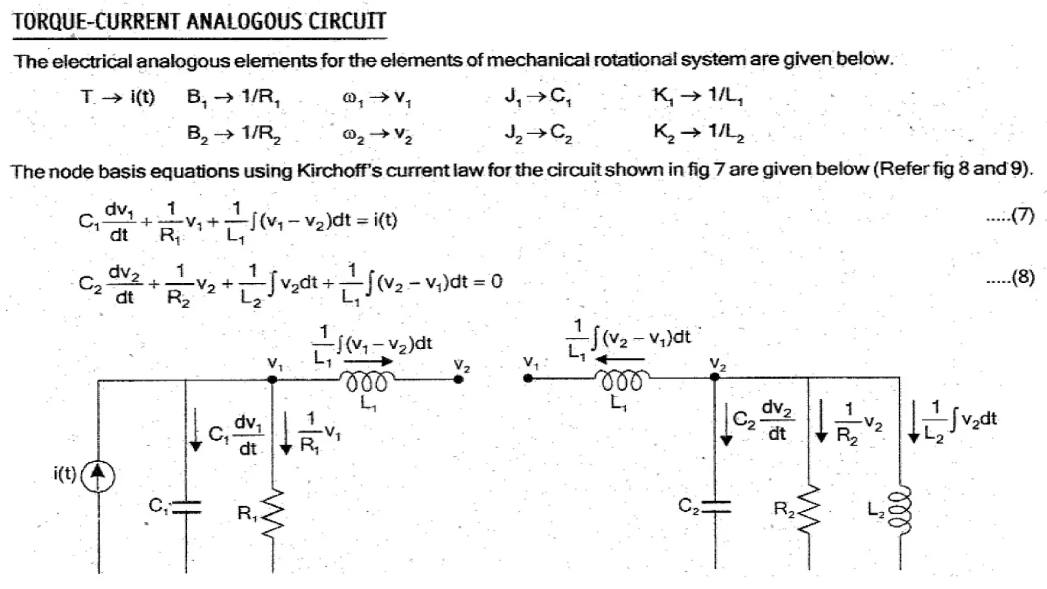
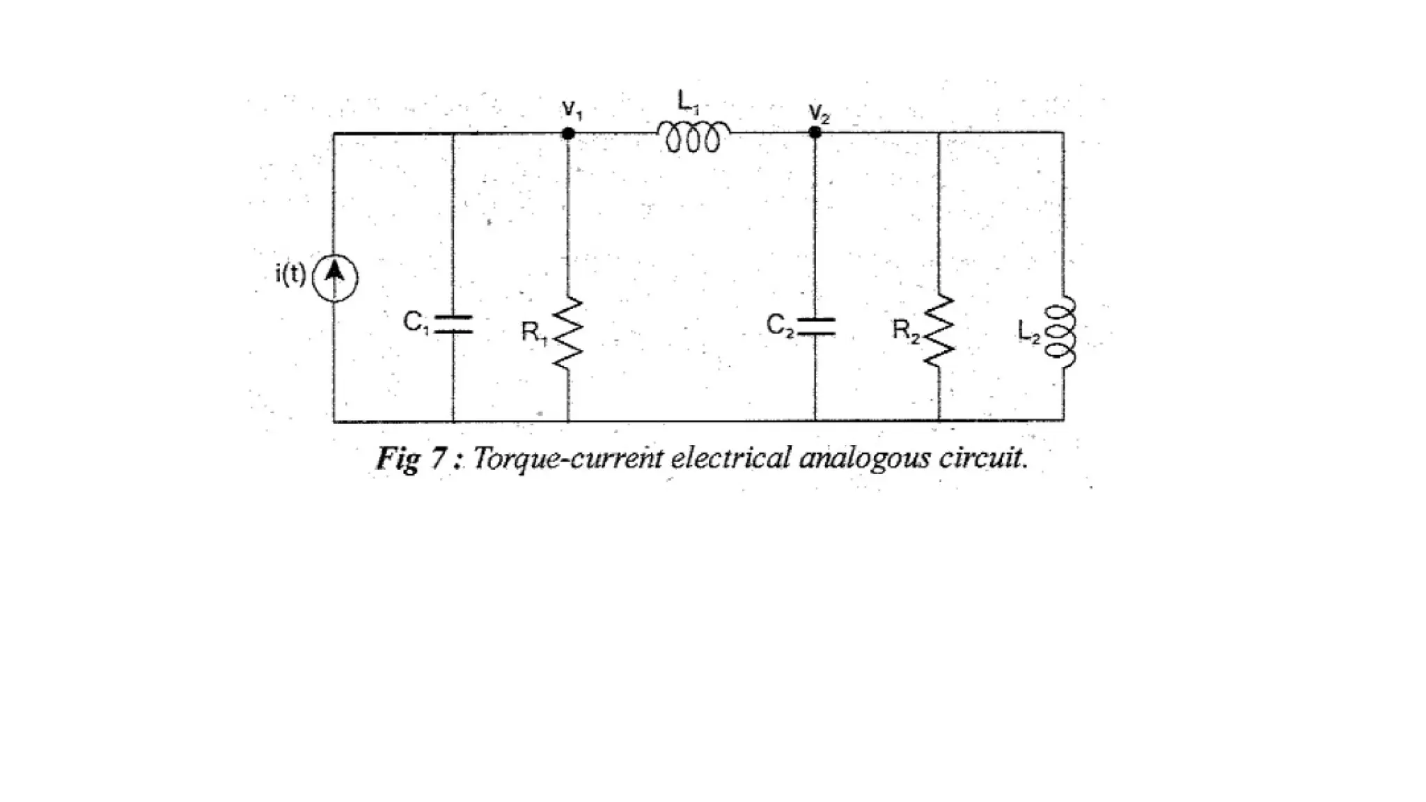
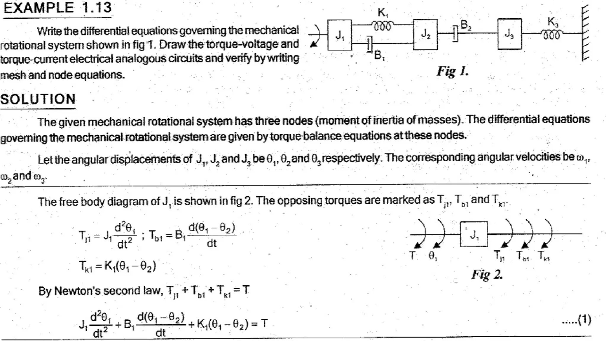
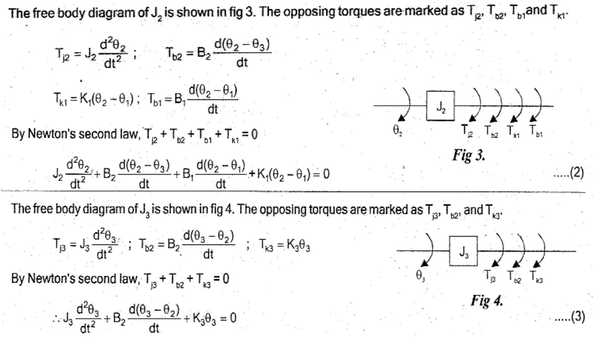
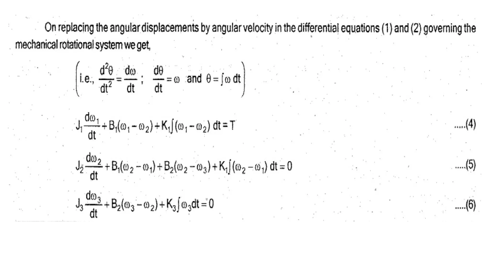
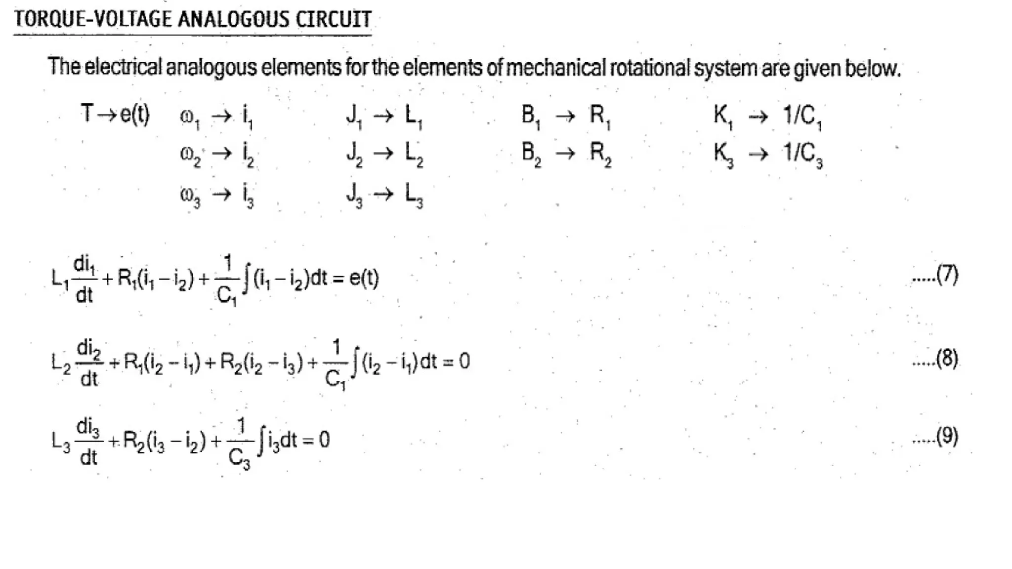
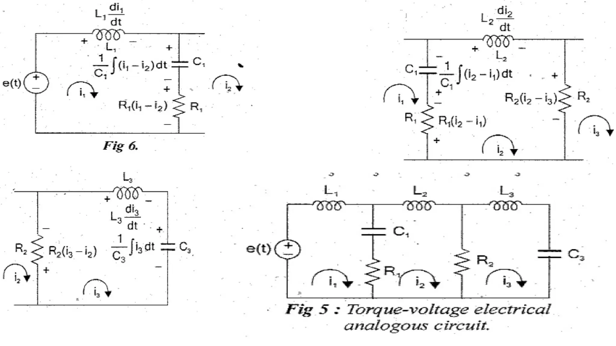
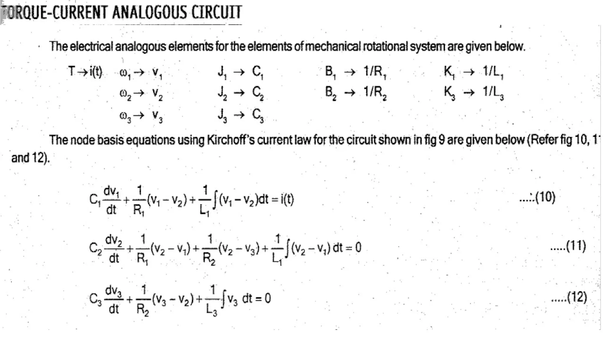
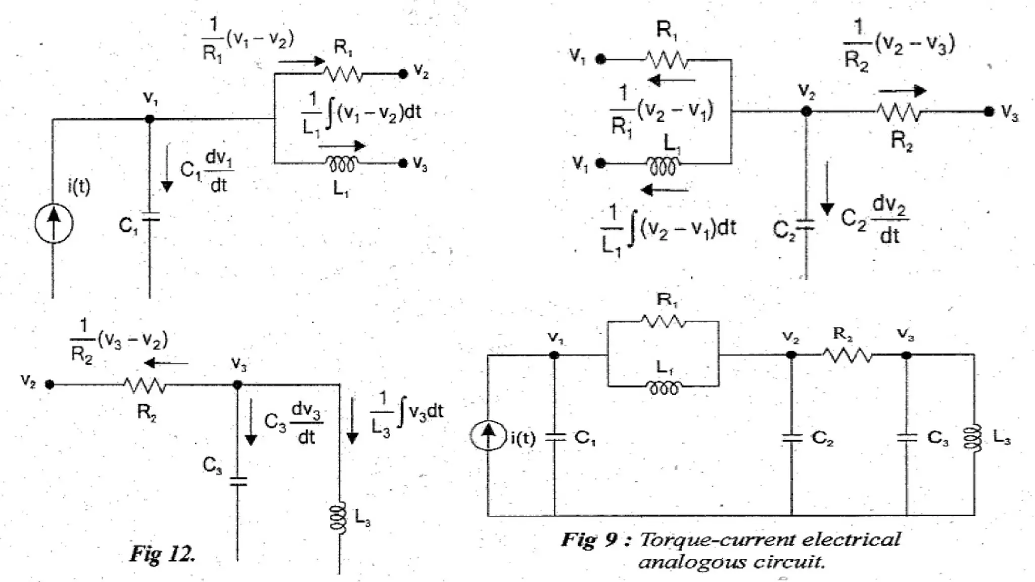
Electrical Analogous ofMechanical Rotational Systems
• The 3 basic elements moment of inertia, rotational dashpot and torsional spring are
used in modelling mechanical systems are analogous to resistance, inductance and
capacitance of electrical systems.
• The i/p torque in mechanical system is analogous to either voltage or current sourse
in electrical systems.
• The o/p angular velocity in mechanical system is analogous to either current or
voltage in an electrical system.
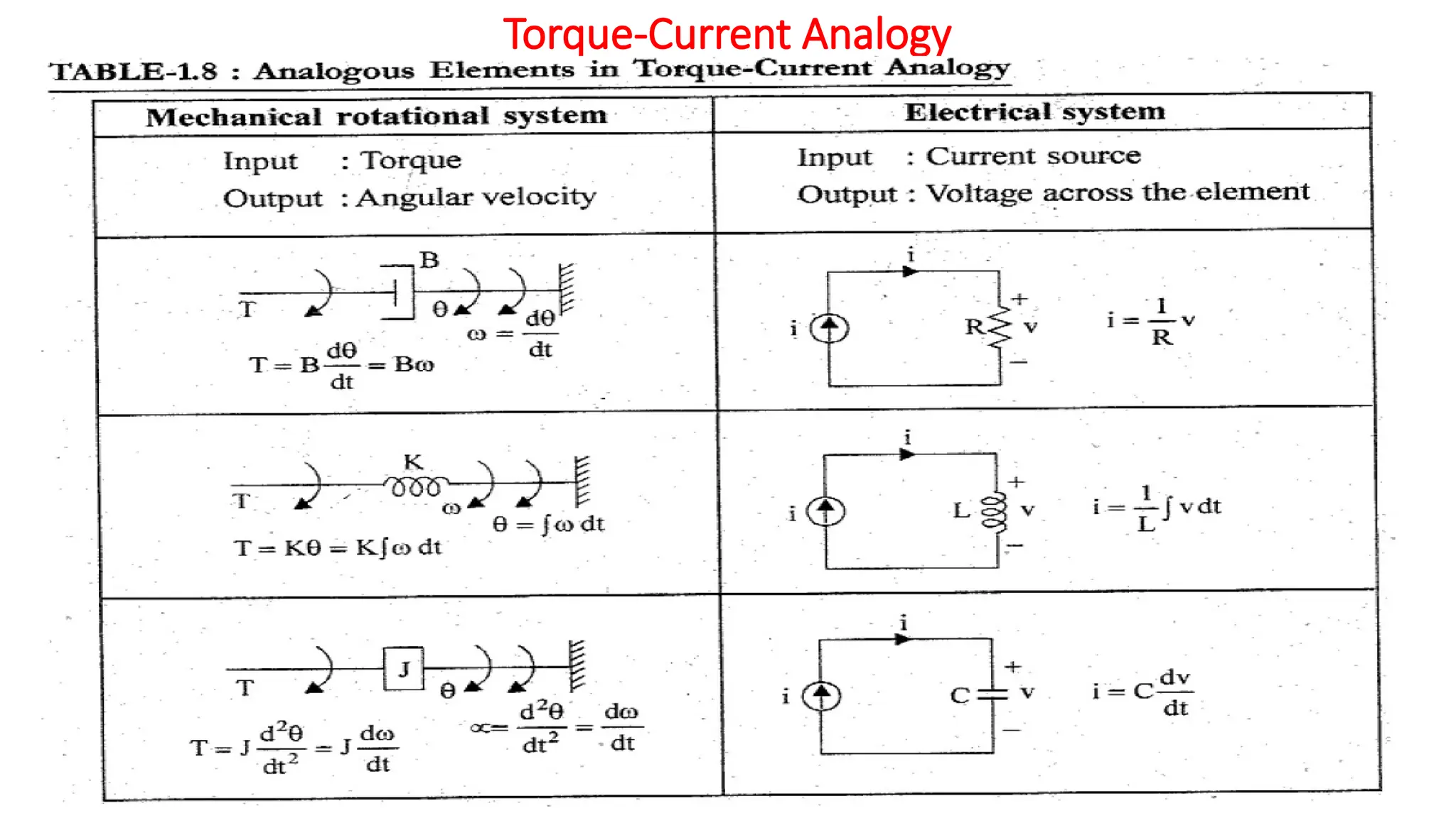
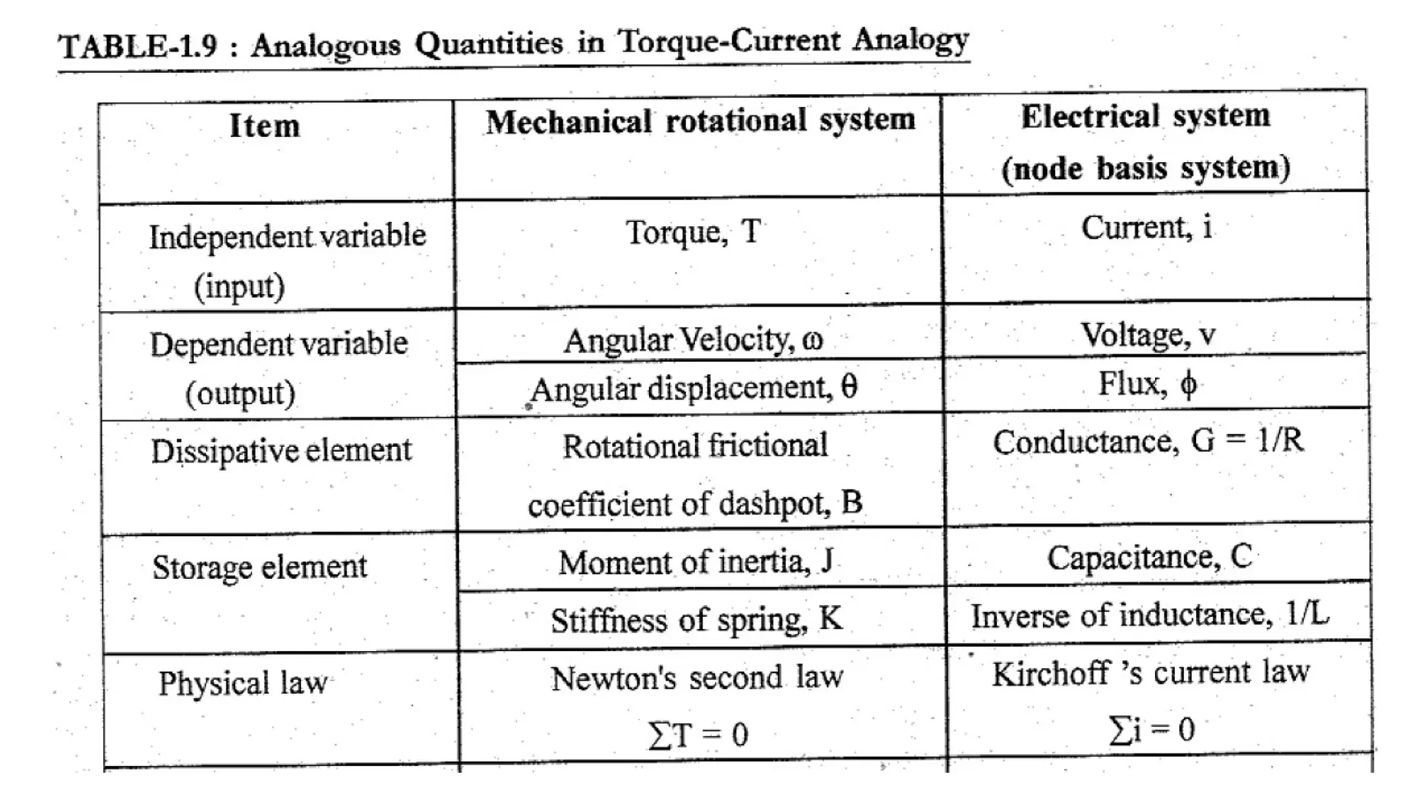
• Since the electrical systems has two types of inputs either voltage or current, there
are two types of analogies: Torque-Voltage and Torque-Current Analogy.