Download to read offline
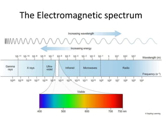


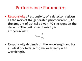

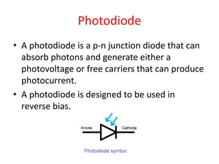
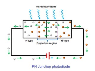

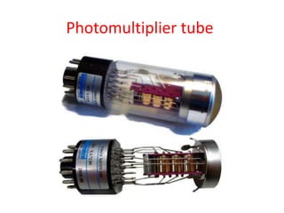

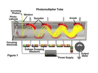


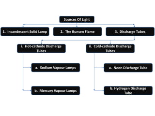


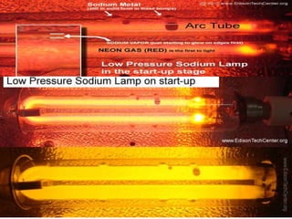


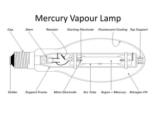


The document discusses spectral instruments, which analyze the interaction between matter and the electromagnetic spectrum, focusing primarily on photon detectors such as photodiodes and photomultiplier tubes. It provides details on their working principles, performance parameters, and various applications in fields like nuclear medicine and light measurement. The document also covers different light sources used in conjunction with these instruments, including incandescent lamps and discharge tubes.


![Human Reproduction [ Reproductive System ] Notes @irfanullah_mehar Irfanullah...](https://cdn.slidesharecdn.com/ss_thumbnails/humanreproductionreproductivesystemnotesirfanullahmeharirfanullahmeharjanantantra-260111172350-56e85778-thumbnail.jpg?width=640&height=640&fit=bounds)


