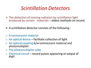
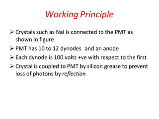
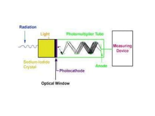
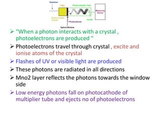
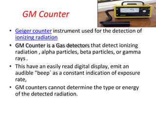
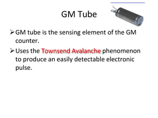
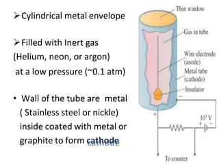
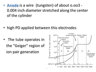
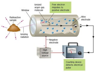
2. Scintillation Detectors
The detection of ionising radiation by scintillation light
produced by certain materials – oldest methods on record.
A scintillation detector consists of the following :
o A luminescent material
o An optical device – facilitate collection of light
o An optical coupling b/w luminescent material and
photomultiplier
o The photomultiplier tube
o Electrical circuit – record pulses appearing at output of
PMT
3. Working Principle
Crystals such as NaI is connected to the PMT as
shown in figure
PMT has 10 to 12 dynodes and an anode
Each dynode is 100 volts +ve with respect to the first
Crystal is coupled to PMT by silicon grease to prevent
loss of photons by reflection
4.
5. “When a photon interacts with a crystal ,
photoelectrons are produced “
Photoelectrons travel through crystal , excite and
ionise atoms of the crystal
Flashes of UV or visible light are produced
These photons are radiated in all directions
Mno2 layer reflects the photons towards the window
side
Low energy photons fall on photocathode of
multiplier tube and ejects no of photoelectrons
6. Photoelectrons are accelerated by potential
applied b/w cathode and first dynode of the tube
On striking first dynode , each photoelectron
ejects several electrons by secondary emission
Electron multiplication process repeated at
subsequent dynodes , each at higher potential
than preceding one
After multiplication of about 10^5 to 10^9 , the
avalanche arrives at collector plate
Produces a voltage pulse at output condenser ,
coupled to an exit pulse amplifying circuit
7. The initial energy of single ionising particle is
transformed to single volt pulse
Whole system enclosed in light tight box –
eliminate effects others than those due to
incident ionising radiation
No of electrons ejected from photocathode α
amount of light reaches it
Amount of light α energy absorbed from photon
beam by crystal
“Size of pulse from the anode α energy of
incident photon in crystal”
8. • ADVANTAGES: higher quantum efficiency and
compact size.
• DISADVANTAGES : Electronic noise is a major
problem due to the small signal amplitude
9. GM Counter
• Geiger counter instrument used for the detection of
ionizing radiation
• GM Counter is a Gas detectors that detect ionizing
radiation , alpha particles, beta particles, or gamma
rays .
• This have an easily read digital display, emit an
audible "beep´ as a constant indication of exposure
rate,
• GM counters cannot determine the type or energy
of the detected radiation.
10. GM Tube
GM tube is the sensing element of the GM
counter.
Uses the Townsend Avalanche phenomenon
to produce an easily detectable electronic
pulse.
11. Cylindrical metal envelope
Filled with Inert gas
(Helium, neon, or argon)
at a low pressure (~0.1 atm)
• Wall of the tube are metal
( Stainless steel or nickle)
inside coated with metal or
graphite to form cathode.
12. • Anode is a wire (tungsten) of about o.oo3 -
0.004 inch diameter stretched along the center
of the cylinder
• high PD applied between this electrodes
• The tube operates in
the "Geiger" region of
ion pair generation
13. WORKING
When ionizing radiation strikes the tube some
molecules of the filled gas are ionized (Directly by
incident radiation or indirectly by means of secondary
electrons produced in the wall of the tube)
This creates positively charged Ions (cation) and
negatively charged (electron).
The strong electric field created by the tube’s
electrodes accelerates the positive ions toward the
cathode and electrons toward the anode.
14. • Due to high volt (GM region 1000v-1400v)
the ions, accelerated by the electric field, can gain enough
energy to produce ionization by collision with gas
molecules. This results in a rapid multiplication of ions and
creates a large no. of electrons avalanche which spread
along the anode.
This is the gas multiplication effect , which is able to
produce a significant output pulse from a single ionizing
event.
15. • One avalanche per original ionizing event will
produce 10^6 to 10^8 excited molecules.
• The excited gas atoms produce uv photons in the
original avalanche.
Moves laterally to the axis of the anode to
instigate further ionizing event by collision with
gas molecule.
16. These collision produce further avalanche and the
process continued in a chain reaction.
This process is known as multiple avalanches
production of multiple avalanches results in an
increased multiplication factor which can produce
109 to 1010 ion pairs
17.
18.
19. • The speed of avalanche is typically 2-4 cm per
microsecond.
• This short, intense pulse of current can be measured
as a count event in the form of a voltage pulse
Dead Time :
After a count has been recorded, it takes the
G-M tube a certain amount of time to reset itself to
be ready to record the next count.
20. • The Dead Time of Geiger tube is the Period between
the initial pulse time and time at which a second
Geiger discharge
• The tubes can produce no further pulses during the
dead time (typically 50 - 100 microseconds)
• The time interval required for GM counter to return
to its original state to deliver full amplitude pulse is
called Recovery Time.
21. Quenching
• If a poor diatomic gas quencher were introduced
to the tube, the positive argon ions, during their
motion toward the cathode, would have multiple
collisions with the quencher gas molecules and
transfer their charge and some energy to them.
• Neutral argon atoms would then be produced
and the quencher gas ions would reach the
cathode instead
22. • Disadvantage of quenching is that for a short
time after a discharge pulse has occurred (the
so-called dead time, which is typically 50 - 100
microseconds), the tube is rendered
insensitive
23. Detection of neutrons
GM tubes will not detect neutrons since these do not ionize the
gas.
To make tube neutron sensitive ,
I. Tube wall should be coated with boron. OR
II. Tube should contain Helium – 3 or boron Tri-fluoride.
The neutron interact with Boron nuclei, producing alpha particles
or directly with the Helium – 3 nuclei producing hydrogen and
tritium ion and electrons.
These charged particles then trigger the normal avalanche process.
24. Characteristics
Geiger counters are used to detect radiation
(low level)
It respond to commonly alpha and beta particles as well as
gamma and x-ray
Has no energy information.
High sensitivity (100% for each ionizing event)
Measures low exposure rates (0.1 mR / hr)
Large dead time (~ 100μs)
large output signal and reasonable cost.
25. Proportional counters
• It works in the proportional region of voltage
response curve.
• Principle is similar to that of GM counter – gas
multiplication effect
26. Difference between propotionl and GM
counter
• The proportional counter is operating in linear mode,
so the energy pulse measured by the detector is
proportional to the energy of the radioactive
particle.
• Thus, the average current flow in the detector is a
function of both the activity (curies) and the energy
(kev) of the source.
• This detector is better at measuring the dose rate of
the source.
27. • The Geiger-Muller detector, on the other hand, operates in
avalanche mode, so the energy pulse measured by the
detector is not proportional to the energy of the
radioactive particle.
• Thus, the average current flow in the detector is a function
of only the activity (curies) of the source. This detector is
better at measuring the activity of the source, and can be
more sensitive to lower energy particles, at the loss of
discrimination of what those particles are.