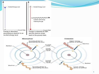
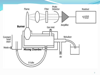
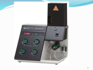
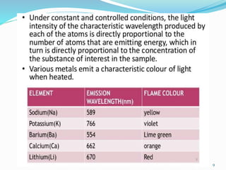
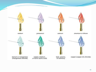
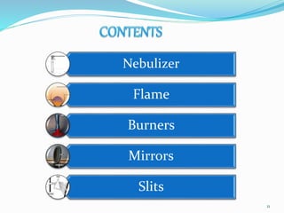
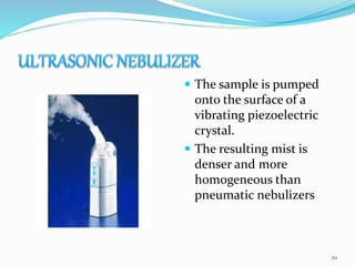
M Asif Shaheen
1
Introduction
 Flame photometry more accurately called Flame
Atomic Emission Spectrometry
 A flame photometer is an instrument used to
determine the concentration of certain metal ions
among them sodium, potassium, calcium and
lithium.
 Flame Photometry is based on measurement of
intensity of the light emitted when a metal is
introduced into flame.
2
Principle
 When a solution of metallic salt is sprayed as fine
droplets into a flame. Due to heat of the flame, the
droplets dry leaving a fine residue of salt. This fine
residue converts into neutral atoms.
 Due to the thermal energy of the flame, the atoms get
excited and there after return to ground state. In this
process of return to ground state, exited atoms emit
radiation of specific wavelength. This wavelength of
radiation emitted is specific for every element
3
 – The wavelength of colour tells what the element is
(qualitative) –
 The colour's intensity tells us how much of the
element present (quantitative)
4
5
7
8
9
10
Nebulizer
Flame
Burners
Mirrors
Slits
11
This is the component of sample delivery system.
which breaks up the bigger liquid droplet to smaller
liquid droplets.
The process of conversion of sample to a fine mist of
finely divided droplets using a jet of compressed gas is
known as Nebulization.
12
Pneumatic
nebulizers
Electro thermal
vaporizer
Ultrasound nebulizer
13
PNEUMATIC
NEBULIZERS
CONCENTRIC
TUBES
CROSS
FLOW
BAGINGTON
FRITTED
DISK
14
 The liquid sample is
sucked through a
capillary tube by a high
pressure jet of gas
flowing around the tip of
the capillary.
 The high velocity breaks
the sample into a mist
and carries it to the
atomization region.
15
 The jet stream flows
right angles to the
capillary tip.
 It uses a high speed
stream of gas
perpendicular to the tip
of the sample capillary
16
 The jet is pumped
through a small orifice in
a sphere on which a thin
film of sample flows
 In this type of nebulizer
the sample solution
flows freely over small
aperture, rather than
passing through a fine
capillary
17
 The sample is pumped
into a fritted disk
through which the gas
jet is flowing and this
gives fine aerosol than
others
 High efficiencies can be
obtained by introducing
the sample at
predetermined location
of the fritted surface
18
 It is an electro thermal
vaporizer contains an
evaporator in a closed
chamber through which
an inert gas carries the
vaporized sample into
the atomizer
19
 The sample is pumped
onto the surface of a
vibrating piezoelectric
crystal.
 The resulting mist is
denser and more
homogeneous than
pneumatic nebulizers
20
21
 It should have proper temperature
 Temperature should remain constant throughout the
operation
 There should not be any fluctuation during burning
To convert the analyte of the liquid sample into
vapour state
To decompose the analyte into atoms and simple
molecules
To excite the formed atoms/free atoms/simple
molecules to emit radiant energy
22
Mecker burner
Total
consumption
burner
Premix of
laminar flow
burner
Lundergraph
burner
Shielded
Burner
Nitrous
Oxide-
Acetylene
Flames
23
 This burner was used
earlier and employed
natural gas and oxygen.
Produces relatively low
temp. and low excitation
energies. This are best
used for ALKALI metals
only. Now-a-days it is not
used.
24
 In this burner fuel and
oxidant are hydrogen
and oxygen gases.
Sample solution is
aspirated through a
capillary by high
pressure of fuel and
Oxidant and burnt at the
tip of burner. Entire
sample is consumed.
25
 In this type of the
burner, aspirated
sample, fuel and oxidant
are thoroughly mixed
before reaching the
burner opening and then
entering the flame.
There is high loss of
sample(95%) as large
droplets are drained out.
26
 In this sample and air is
mixed in a chamber, this
mixed composition is
send to fuel nozzle
where it is atomized.
Here the sample reaches
the flame is only about
5%
27
 In this flame was
shielded from the
ambient atmosphere by a
stream of inert gas.
Shielding is done to get
better analytical
sensitivity and quieter
flame
28
 These flames were superior
to other flames for
effectively producing free
atoms. The drawback of it
is the high temperature
reduces its usefulness for
the determination of alkali
metals as they are easily
ionized and Intense
background emission,
which makes the
measurement of metal
emission very difficult
NITROUS OXIDE ACETYLENE FLAME
29
Fuel Oxidant Temperature 0C
Natural gas Air 1700-1900
Natural gas Oxygen 2700-2800
Hydrogen Air 2000-2100
Hydrogen Oxygen 2550-2700
Acetylene Air 2100-2400
Acetylene Oxygen 3050-3150
Acetylene Nitrous oxide 2600-2800
30
31
Flame Photometry
Non Flame Atomizers
For example: Heated Gravite Furnace
Sample evaporation→ time and temp. controlled drying and ashing
Advantages
1. small samples are analysed
2. 1000-fold more sensitive than flame
3. Oven is adaptable to determination of solid samples
Disadvantages
1. Low accuracy 2. Low precision
2. More ionic interferences due to very high temp.
 The radiation from the
flame is emitted in all the
directions in space. Much
of the radiation is lost and
loss of signal results. A
mirror is located behind
the burner to reflect the
radiation back to the
entrance slit of the
monochromator. The
reflecting surface of the
mirror is front-faced.
32
 The entrance and exit slits are
used before and after the
dispersion elements.
 The entrance slit cuts off
most if radiation from the
surroundings and allows only
the radiation from the flame
and the mirror reflection of
flame to enter the optical
system.
 The exit slit is placed after
the monochromator and
allows only the selected
wavelength range to pass
through the detector
33
Photocell
34
 Measures the amount of light passing through the sample.
 Usually works by converting light signal into electrical signal
 The least expensive of the devices is known as a barrier-layer cell,
or photocell.
 The photocell is composed of a film of light-sensitive material,
frequently selenium, on a plate of iron. Over the light-sensitive
material is a thin, transparent layer of silver. When exposed to
light, electrons in the light-sensitive material are excited and
released to flow to the highly conductive silver in comparison
with the silver, a moderate resistance opposes the electron flow
toward the iron, forming a hypothetical barrier to flow in that
direction. Consequently, this cell generates its own electromotive
force, which can be measured. The produced current is
proportional to incident radiation.
35
Phototube
 The third major type of light detector is the photomultiplier (PM)
tube, which detects and amplifies radiant energy.
 incident light strikes the coated cathode, emitting electrons. The
electrons are attracted to a series of anodes, known as dynodes,
each having a successively higher positive voltage These dynodes are
of a material that gives off many secondary electrons when hit by
single electrons. Initial electron emission at the cathode triggers a
multiple cascade of electrons within the PM tube itself. Because of
this amplification, the PM tube is 200 times more sensitive than the
phototube
36
 PM tubes are used in instruments designed to be extremely sensitive to very low light
levels and light flashes of very short duration.
 The accumulation of electrons striking the anode produces a current signal,
measured in amperes, that is proportional to the initial intensity of the light. The
analog signal is converted first to a voltage and then to a digital signal through the
use of an analog to- digital (A/D) converter. Digital signals are processed
electronically to produce absorbance readings
 Readout device.
 In the past nearly all spectrophotometer used ammeters or galvanometers. Newer digital
devices and printers have now replaced these, and many instruments relay their electrical
output directly to computer circuits where calculations are performed, allowing direct
reporting of sample concentration.
 Microprocessor and recorders
39
Limitations
 Limited number of elements that can be analyzed.
 The sample requires to be introduced as solution into
fine droplets. Many metallic salts, soil, plant and other
compounds are insoluble in common solvents. Hence,
they can’t be analyzed by this method.
 Since sample is volatilized, if small amount of sample
is present, it is tough to analyze by this method. As
some of it gets wasted by vaporization.
 Further during solubilisation with solvents, other
impurities might mix up with sample and may lead to
errors in the spectra observed.
40
41
Chatwal & Anand; Instrumental Methods of Chemical
Analysis, 5/e 2013, page no- 2.370 to 2.375, Himalaya
Publishing House.
B.K Sharma; Instrumental Methods of Chemical
Analysis, 26/e 2007, page no- 430 to 437, GOEL
Publishing House.
42
43

Flame photometer (Atomic Emission Spectroscopy) Flame emission spectroscopy

  • 1.
  • 2.
    Introduction  Flame photometrymore accurately called Flame Atomic Emission Spectrometry  A flame photometer is an instrument used to determine the concentration of certain metal ions among them sodium, potassium, calcium and lithium.  Flame Photometry is based on measurement of intensity of the light emitted when a metal is introduced into flame. 2
  • 3.
    Principle  When asolution of metallic salt is sprayed as fine droplets into a flame. Due to heat of the flame, the droplets dry leaving a fine residue of salt. This fine residue converts into neutral atoms.  Due to the thermal energy of the flame, the atoms get excited and there after return to ground state. In this process of return to ground state, exited atoms emit radiation of specific wavelength. This wavelength of radiation emitted is specific for every element 3
  • 4.
     – Thewavelength of colour tells what the element is (qualitative) –  The colour's intensity tells us how much of the element present (quantitative) 4
  • 5.
  • 7.
  • 8.
  • 9.
  • 10.
  • 11.
  • 12.
    This is thecomponent of sample delivery system. which breaks up the bigger liquid droplet to smaller liquid droplets. The process of conversion of sample to a fine mist of finely divided droplets using a jet of compressed gas is known as Nebulization. 12
  • 13.
  • 14.
  • 15.
     The liquidsample is sucked through a capillary tube by a high pressure jet of gas flowing around the tip of the capillary.  The high velocity breaks the sample into a mist and carries it to the atomization region. 15
  • 16.
     The jetstream flows right angles to the capillary tip.  It uses a high speed stream of gas perpendicular to the tip of the sample capillary 16
  • 17.
     The jetis pumped through a small orifice in a sphere on which a thin film of sample flows  In this type of nebulizer the sample solution flows freely over small aperture, rather than passing through a fine capillary 17
  • 18.
     The sampleis pumped into a fritted disk through which the gas jet is flowing and this gives fine aerosol than others  High efficiencies can be obtained by introducing the sample at predetermined location of the fritted surface 18
  • 19.
     It isan electro thermal vaporizer contains an evaporator in a closed chamber through which an inert gas carries the vaporized sample into the atomizer 19
  • 20.
     The sampleis pumped onto the surface of a vibrating piezoelectric crystal.  The resulting mist is denser and more homogeneous than pneumatic nebulizers 20
  • 21.
  • 22.
     It shouldhave proper temperature  Temperature should remain constant throughout the operation  There should not be any fluctuation during burning To convert the analyte of the liquid sample into vapour state To decompose the analyte into atoms and simple molecules To excite the formed atoms/free atoms/simple molecules to emit radiant energy 22
  • 23.
    Mecker burner Total consumption burner Premix of laminarflow burner Lundergraph burner Shielded Burner Nitrous Oxide- Acetylene Flames 23
  • 24.
     This burnerwas used earlier and employed natural gas and oxygen. Produces relatively low temp. and low excitation energies. This are best used for ALKALI metals only. Now-a-days it is not used. 24
  • 25.
     In thisburner fuel and oxidant are hydrogen and oxygen gases. Sample solution is aspirated through a capillary by high pressure of fuel and Oxidant and burnt at the tip of burner. Entire sample is consumed. 25
  • 26.
     In thistype of the burner, aspirated sample, fuel and oxidant are thoroughly mixed before reaching the burner opening and then entering the flame. There is high loss of sample(95%) as large droplets are drained out. 26
  • 27.
     In thissample and air is mixed in a chamber, this mixed composition is send to fuel nozzle where it is atomized. Here the sample reaches the flame is only about 5% 27
  • 28.
     In thisflame was shielded from the ambient atmosphere by a stream of inert gas. Shielding is done to get better analytical sensitivity and quieter flame 28
  • 29.
     These flameswere superior to other flames for effectively producing free atoms. The drawback of it is the high temperature reduces its usefulness for the determination of alkali metals as they are easily ionized and Intense background emission, which makes the measurement of metal emission very difficult NITROUS OXIDE ACETYLENE FLAME 29
  • 30.
    Fuel Oxidant Temperature0C Natural gas Air 1700-1900 Natural gas Oxygen 2700-2800 Hydrogen Air 2000-2100 Hydrogen Oxygen 2550-2700 Acetylene Air 2100-2400 Acetylene Oxygen 3050-3150 Acetylene Nitrous oxide 2600-2800 30
  • 31.
    31 Flame Photometry Non FlameAtomizers For example: Heated Gravite Furnace Sample evaporation→ time and temp. controlled drying and ashing Advantages 1. small samples are analysed 2. 1000-fold more sensitive than flame 3. Oven is adaptable to determination of solid samples Disadvantages 1. Low accuracy 2. Low precision 2. More ionic interferences due to very high temp.
  • 32.
     The radiationfrom the flame is emitted in all the directions in space. Much of the radiation is lost and loss of signal results. A mirror is located behind the burner to reflect the radiation back to the entrance slit of the monochromator. The reflecting surface of the mirror is front-faced. 32
  • 33.
     The entranceand exit slits are used before and after the dispersion elements.  The entrance slit cuts off most if radiation from the surroundings and allows only the radiation from the flame and the mirror reflection of flame to enter the optical system.  The exit slit is placed after the monochromator and allows only the selected wavelength range to pass through the detector 33
  • 34.
    Photocell 34  Measures theamount of light passing through the sample.  Usually works by converting light signal into electrical signal  The least expensive of the devices is known as a barrier-layer cell, or photocell.  The photocell is composed of a film of light-sensitive material, frequently selenium, on a plate of iron. Over the light-sensitive material is a thin, transparent layer of silver. When exposed to light, electrons in the light-sensitive material are excited and released to flow to the highly conductive silver in comparison with the silver, a moderate resistance opposes the electron flow toward the iron, forming a hypothetical barrier to flow in that direction. Consequently, this cell generates its own electromotive force, which can be measured. The produced current is proportional to incident radiation.
  • 35.
  • 36.
    Phototube  The thirdmajor type of light detector is the photomultiplier (PM) tube, which detects and amplifies radiant energy.  incident light strikes the coated cathode, emitting electrons. The electrons are attracted to a series of anodes, known as dynodes, each having a successively higher positive voltage These dynodes are of a material that gives off many secondary electrons when hit by single electrons. Initial electron emission at the cathode triggers a multiple cascade of electrons within the PM tube itself. Because of this amplification, the PM tube is 200 times more sensitive than the phototube 36
  • 37.
     PM tubesare used in instruments designed to be extremely sensitive to very low light levels and light flashes of very short duration.  The accumulation of electrons striking the anode produces a current signal, measured in amperes, that is proportional to the initial intensity of the light. The analog signal is converted first to a voltage and then to a digital signal through the use of an analog to- digital (A/D) converter. Digital signals are processed electronically to produce absorbance readings
  • 38.
     Readout device. In the past nearly all spectrophotometer used ammeters or galvanometers. Newer digital devices and printers have now replaced these, and many instruments relay their electrical output directly to computer circuits where calculations are performed, allowing direct reporting of sample concentration.  Microprocessor and recorders
  • 39.
  • 40.
    Limitations  Limited numberof elements that can be analyzed.  The sample requires to be introduced as solution into fine droplets. Many metallic salts, soil, plant and other compounds are insoluble in common solvents. Hence, they can’t be analyzed by this method.  Since sample is volatilized, if small amount of sample is present, it is tough to analyze by this method. As some of it gets wasted by vaporization.  Further during solubilisation with solvents, other impurities might mix up with sample and may lead to errors in the spectra observed. 40
  • 41.
  • 42.
    Chatwal & Anand;Instrumental Methods of Chemical Analysis, 5/e 2013, page no- 2.370 to 2.375, Himalaya Publishing House. B.K Sharma; Instrumental Methods of Chemical Analysis, 26/e 2007, page no- 430 to 437, GOEL Publishing House. 42
  • 43.

Editor's Notes

  • #19 Fritted glass is finely porous glass through which gas or liquid may pass
  • #21 Piezoelectricity /piˌeɪzoʊˌilɛkˈtrɪsɪti/ is the electric charge that accumulates in certain solid materials (such as crystals, certain ceramics, and biological matter such as bone, DNA and various proteins)[1] in response to applied mechanical stress. The word piezoelectricity means electricity resulting from pressure