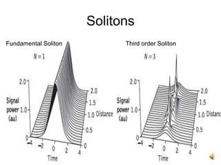
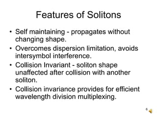
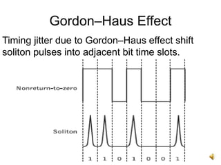
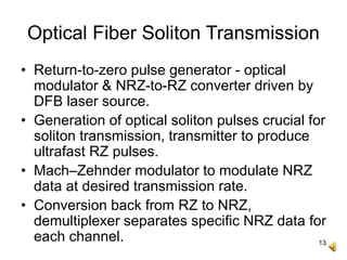
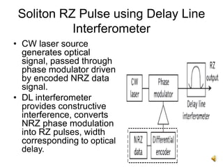
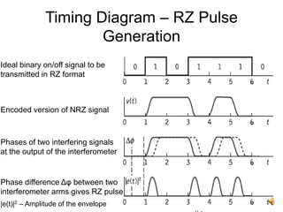
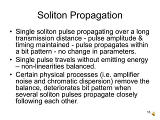
1
Soliton Systems
MEC
2
Contents
• Introduction.
• Features of Solitons.
• Gordon-Haus Effect.
• Soliton Transmission System.
• Waveform / Timing Diagram.
• Challenges.
3
Solitons
• First described in 1834 by John Scott
Russell.
• Soliton or Solitary wave - self reinforcing
wave packet, maintains shape, propagates
at constant velocity.
• Akira Hasegawa of AT&T Bell Labs - first
to suggest that solitons could exist in
optical fibers.
• 1973 - Robin Bullough made the first
mathematical report of existence of optical
solitons.
4
Solitons
• Nonlinear ultrashort optical pulses of pico-
seconds width.
• Maintains shape while propagating at a
constant velocity, no distortion.
• Caused by a cancellation of nonlinear and
dispersive effects in the medium.
• Potential to support very high optical
transmission rates (Tb/s) over long distances.
• Inherent stability facilitates long-distance
transmission without using repeaters, could
double transmission capacity.
5
Solitons
Fundamental Soliton Third order Soliton
6
Features of Solitons
• Self maintaining - propagates without
changing shape.
• Overcomes dispersion limitation, avoids
intersymbol interference.
• Collision Invariant - soliton shape
unaffected after collision with another
soliton.
• Collision invariance provides for efficient
wavelength division multiplexing.
7
Gordon–Haus Effect
• Timing jitter - amplified spontaneous
emission noise on optically amplified fiber
link produce random variations of solitons’
central frequencies.
• Chromatic dispersion within single-mode
fiber converts variations in frequency to
jitter in pulse arrival times.
• Pulses move out of correct bit time slots,
create errors in soliton transmission.
8
Gordon–Haus Effect
Timing jitter due to Gordon–Haus effect shift
soliton pulses into adjacent bit time slots.
9
Gordon–Haus Effect
• ASE noise and Gordon–Haus jitter limit
maximum permissible transmission distance
for optical soliton transmission system.
• Additive nature of the ASE noise - large SNR
required to differentiate binary zeros from
ones - necessites increasing optical signal
power for longer transmission distances.
10
Gordon–Haus Effect
• At such transmission distances, Gordon–
Haus effect dominates, cause bit errors
due to random displacements of pulses
ending up in neighboring time slots.
• Balance between effect of ASE noise and
Gordon–Haus jitter required.
• Use of in-line modulation or synchronous
modulation schemes reduce unwanted
noise sources, very long transmission
distances (>10 000 km) achieved.
11
Gordon–Haus Effect
Acceptable range of values for ASE noise and Gordon–Haus jitter
12
Optical Fiber Soliton Transmission
13
Optical Fiber Soliton Transmission
• Return-to-zero pulse generator - optical
modulator & NRZ-to-RZ converter driven by
DFB laser source.
• Generation of optical soliton pulses crucial for
soliton transmission, transmitter to produce
ultrafast RZ pulses.
• Mach–Zehnder modulator to modulate NRZ
data at desired transmission rate.
• Conversion back from RZ to NRZ,
demultiplexer separates specific NRZ data for
each channel.
14
Soliton RZ Pulse using Delay Line
Interferometer
• CW laser source
generates optical
signal, passed through
phase modulator driven
by encoded NRZ data
signal.
• DL interferometer
provides constructive
interference, converts
NRZ phase modulation
into RZ pulses, width
corresponding to optical
delay.
15
Timing Diagram – RZ Pulse
Generation
Ideal binary on/off signal to be
transmitted in RZ format
Encoded version of NRZ signal
Phases of two interfering signals
at the output of the interferometer
Phase difference Δφ between two
interferometer arms gives RZ pulse
|e(t)|2 – Amplitude of the envelope
16
Soliton Propagation
• Single soliton pulse propagating over a long
transmission distance - pulse amplitude &
timing maintained - pulse propagates within
a bit pattern - no change in parameters.
• Single pulse travels without emitting energy
– non-linearities balanced.
• Certain physical processes (i.e. amplifier
noise and chromatic dispersion) remove the
balance, deteriorates bit pattern when
several soliton pulses propagate closely
following each other.
17
Soliton Propagation
• Soliton interaction cause one pulse shed
energy to another, produces destructive
interference.
• Maintain safe distance between two
consecutive soliton pulses to avoid any
destructive interaction.
• Strength of interaction - distance between
two interacting soliton pulses.
• Avoidance of interaction necessitates
large bandwidth capacity.
18
Soliton Propagation
Soliton bit stream Soliton collision
Safe separation distances
T0 – Bit duration, τ – Soliton pulse width
19
Soliton Propagation
• Soliton transmission systems can be
single-wavelength or multiwavelength
channel.
• Single-wavelength channel system - one
transmitter used to launch the RZ pulses
onto optical fiber.
• Multiwavelength-channel systems -
several transmitters simultaneously, data
multiplexed using WDM.
20
Soliton Propagation
• Ability to generate accurate ultrashort pulses
declines with increasing transmission rate.
• At high transmission rates over long
distances, optical soliton pulses suffer from
fiber attenuation & dispersive effects, low
SNR, need for optical amplification &
dispersion compensation – DMS systems.
• Dispersion and polarization limit increase of
transmission rates and distances.
21
Soliton Transmission
• Maximum allowable transmission bit rate for
soliton pulses:
• q0 - separation of soliton pulses over a bit
period length is dimensionless, τ - soliton
pulse width, T0 - duration of bit period.
22
Soliton Transmission
• q0 determines pulse separation, provides
value of separation between adjacent
soliton pulses to avoid interaction.
• T0/τ determines nature of nonlinear
propagation for soliton pulses.
• 0 < T0/τ < 1 for higher interaction strength,
interaction decreases when T0/τ >>1.
• Rule of thumb - T0/τ of 6 to 8 to ensure safe
distance b/w adjacent soliton pulses.
23
Dispersion Length
• Length LD of single-mode optical fiber over
which the pulse width of soliton broadens
significantly due to dispersion.
β2 - second-order dispersion coefficient, τ -
soliton pulse width, LA - optical amplifier
spacing, LA<<LD.
24
Dispersion Length
• When LA >> LD, main factor affecting the
pulse width and signal power is fiber
attenuation.
• α LD describes propagation of such soliton
pulses more accurately.
• When αLD ≥ 1, there will be large fiber
attenuation, optical pulses cannot maintain
their soliton nature.
• αLD ≤ 1 to preserve soliton nature.
25
Thank You

Soliton systems

  • 1.
  • 2.
    2 Contents • Introduction. • Featuresof Solitons. • Gordon-Haus Effect. • Soliton Transmission System. • Waveform / Timing Diagram. • Challenges.
  • 3.
    3 Solitons • First describedin 1834 by John Scott Russell. • Soliton or Solitary wave - self reinforcing wave packet, maintains shape, propagates at constant velocity. • Akira Hasegawa of AT&T Bell Labs - first to suggest that solitons could exist in optical fibers. • 1973 - Robin Bullough made the first mathematical report of existence of optical solitons.
  • 4.
    4 Solitons • Nonlinear ultrashortoptical pulses of pico- seconds width. • Maintains shape while propagating at a constant velocity, no distortion. • Caused by a cancellation of nonlinear and dispersive effects in the medium. • Potential to support very high optical transmission rates (Tb/s) over long distances. • Inherent stability facilitates long-distance transmission without using repeaters, could double transmission capacity.
  • 5.
  • 6.
    6 Features of Solitons •Self maintaining - propagates without changing shape. • Overcomes dispersion limitation, avoids intersymbol interference. • Collision Invariant - soliton shape unaffected after collision with another soliton. • Collision invariance provides for efficient wavelength division multiplexing.
  • 7.
    7 Gordon–Haus Effect • Timingjitter - amplified spontaneous emission noise on optically amplified fiber link produce random variations of solitons’ central frequencies. • Chromatic dispersion within single-mode fiber converts variations in frequency to jitter in pulse arrival times. • Pulses move out of correct bit time slots, create errors in soliton transmission.
  • 8.
    8 Gordon–Haus Effect Timing jitterdue to Gordon–Haus effect shift soliton pulses into adjacent bit time slots.
  • 9.
    9 Gordon–Haus Effect • ASEnoise and Gordon–Haus jitter limit maximum permissible transmission distance for optical soliton transmission system. • Additive nature of the ASE noise - large SNR required to differentiate binary zeros from ones - necessites increasing optical signal power for longer transmission distances.
  • 10.
    10 Gordon–Haus Effect • Atsuch transmission distances, Gordon– Haus effect dominates, cause bit errors due to random displacements of pulses ending up in neighboring time slots. • Balance between effect of ASE noise and Gordon–Haus jitter required. • Use of in-line modulation or synchronous modulation schemes reduce unwanted noise sources, very long transmission distances (>10 000 km) achieved.
  • 11.
    11 Gordon–Haus Effect Acceptable rangeof values for ASE noise and Gordon–Haus jitter
  • 12.
  • 13.
    13 Optical Fiber SolitonTransmission • Return-to-zero pulse generator - optical modulator & NRZ-to-RZ converter driven by DFB laser source. • Generation of optical soliton pulses crucial for soliton transmission, transmitter to produce ultrafast RZ pulses. • Mach–Zehnder modulator to modulate NRZ data at desired transmission rate. • Conversion back from RZ to NRZ, demultiplexer separates specific NRZ data for each channel.
  • 14.
    14 Soliton RZ Pulseusing Delay Line Interferometer • CW laser source generates optical signal, passed through phase modulator driven by encoded NRZ data signal. • DL interferometer provides constructive interference, converts NRZ phase modulation into RZ pulses, width corresponding to optical delay.
  • 15.
    15 Timing Diagram –RZ Pulse Generation Ideal binary on/off signal to be transmitted in RZ format Encoded version of NRZ signal Phases of two interfering signals at the output of the interferometer Phase difference Δφ between two interferometer arms gives RZ pulse |e(t)|2 – Amplitude of the envelope
  • 16.
    16 Soliton Propagation • Singlesoliton pulse propagating over a long transmission distance - pulse amplitude & timing maintained - pulse propagates within a bit pattern - no change in parameters. • Single pulse travels without emitting energy – non-linearities balanced. • Certain physical processes (i.e. amplifier noise and chromatic dispersion) remove the balance, deteriorates bit pattern when several soliton pulses propagate closely following each other.
  • 17.
    17 Soliton Propagation • Solitoninteraction cause one pulse shed energy to another, produces destructive interference. • Maintain safe distance between two consecutive soliton pulses to avoid any destructive interaction. • Strength of interaction - distance between two interacting soliton pulses. • Avoidance of interaction necessitates large bandwidth capacity.
  • 18.
    18 Soliton Propagation Soliton bitstream Soliton collision Safe separation distances T0 – Bit duration, τ – Soliton pulse width
  • 19.
    19 Soliton Propagation • Solitontransmission systems can be single-wavelength or multiwavelength channel. • Single-wavelength channel system - one transmitter used to launch the RZ pulses onto optical fiber. • Multiwavelength-channel systems - several transmitters simultaneously, data multiplexed using WDM.
  • 20.
    20 Soliton Propagation • Abilityto generate accurate ultrashort pulses declines with increasing transmission rate. • At high transmission rates over long distances, optical soliton pulses suffer from fiber attenuation & dispersive effects, low SNR, need for optical amplification & dispersion compensation – DMS systems. • Dispersion and polarization limit increase of transmission rates and distances.
  • 21.
    21 Soliton Transmission • Maximumallowable transmission bit rate for soliton pulses: • q0 - separation of soliton pulses over a bit period length is dimensionless, τ - soliton pulse width, T0 - duration of bit period.
  • 22.
    22 Soliton Transmission • q0determines pulse separation, provides value of separation between adjacent soliton pulses to avoid interaction. • T0/τ determines nature of nonlinear propagation for soliton pulses. • 0 < T0/τ < 1 for higher interaction strength, interaction decreases when T0/τ >>1. • Rule of thumb - T0/τ of 6 to 8 to ensure safe distance b/w adjacent soliton pulses.
  • 23.
    23 Dispersion Length • LengthLD of single-mode optical fiber over which the pulse width of soliton broadens significantly due to dispersion. β2 - second-order dispersion coefficient, τ - soliton pulse width, LA - optical amplifier spacing, LA<<LD.
  • 24.
    24 Dispersion Length • WhenLA >> LD, main factor affecting the pulse width and signal power is fiber attenuation. • α LD describes propagation of such soliton pulses more accurately. • When αLD ≥ 1, there will be large fiber attenuation, optical pulses cannot maintain their soliton nature. • αLD ≤ 1 to preserve soliton nature.
  • 25.