TrustArc Webinar - Unlock the Power of AI-Driven Data Discovery
D04532226
1. IOSR Journal of Engineering (IOSRJEN) www.iosrjen.org
ISSN (e): 2250-3021, ISSN (p): 2278-8719
Vol. 04, Issue 05 (May. 2014), ||V3|| PP 22-26
International organization of Scientific Research 22 | P a g e
Design and Performance Analysis of Optical Transmission
System
Virendra kumar, A.K.Jaiswal, Mukesh kumar, Nilesh agrawal, Rohini Saxena
1 PG Student ECE, SHIATS (Deemed-to-be-university), U.P., India,
2 professor, ECE, SHIATS (Deemed-to-be-university), U.P., India,
3,4,5 Assistant professor, ECE, SHIATS (Deemed-to-be-university), U.P., India,
Abstract: - In this paper we have discussed a simulated long haul optical transmission system Over the single
mode fibre which is prove to the liner chromatic dispersion as well as Non linearity. Both Parameter have been
of great concern as these confine the overall Efficiency of the system. Loop control is commonly chosen as an
important component in optical communication system. Loop control is very simple, has a multiplier for
increasing the length of optical fibre. E DFA is used for amplification of the signal. The objective of this paper
is to analyze the performance of two different modulation scheme i.e RZ and NRZ modulation format at
10GB/s. RZ and NRZ modulation format is the scheme used to avoid intersymbol interference on an optical
carrier wave for transmission over optical fibre. Each modulation method has its own advantages and
disadvantages for the particular channel conditions. The performance of RZ and NRZ based simulated optical
communication system with single channel over single mode fibre is investigated. Based on modulated outputs
of RZ and NRZ codes, a comprehensive comparison is developed in terms of Q factor BER , eye diagrams and
average input power to establish the merits and demerits of the RZ formats in short as well as long haul optical
communication system.
Keywords: - non return to zero,(NRZ), return to zero( RZ), Q factor ,BER
I. INTRODUCTION
The basic optical transmission system consist three basic component which are fibre media
(transmission channel) light sources input (convert electrical into optical signal)1, light detector as the output
(convert optical signal into electrical signal). loop control is major component used as a multiple optical fibre
communication system. Another key component is EDFA. These provide high bit rate data transmission over
long distance with appropriate optical amplification3. There are two typical choices for the modulation format
of the signal known as the RZ pulse generator and NRZ systems in Optical fibre has been discussed by
analyzing the different modulation format by using different parameters setting. The value of different
parameters has been investigated such as Q factor, BER Eye height input power, ouput power.
Opti System Simulator Software is an advanced, innovative, rapidly developing and powerful software
simulator tool for the design, testing and optimization of virtually any type of optical link in the physical layer
of a broad spectrum of optical networks from ultra-long-haul system . It is an innovative optical communication
system simulation package which was explored by opti Wave Company in order to meet the academic
requirement of the system designers, optical communications engineers, researches .
II. BACK GROUND THEORY
Fibre optic communication is one way to transmit the information or data from one place to another by
sending the pulses of light through an optical. Fibre optic is a natural consequence of the internet growth. Fibre
optic act like an optical wire made it as the most suitable for the communication channel. There are three basics
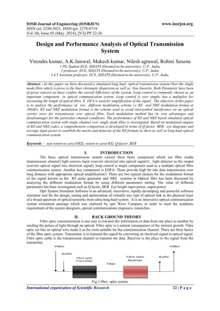
of the fibre optic system. Transmitter is to transmit the signal by converting an electrical signal to optical signal.
Fibre optic cable is the transmission channel to transmit the data. Receiver is the place to the signal from the
transmitter.
Fig 1 fibre optic system
2. Design and Performance Analysis Of Optical Transmission System
International organization of Scientific Research 23 | P a g e
Loop Controller .loop control is an interdisciplinary branch of engineering and mathematics that deals with the
behaviour of dynamical system with input. The external input of a system is called the references. When output
variable of a system need to follow a certain reference over time, a controller manipulates the input to a system
to obtain the desired effect on the output of the system.
III. MODULATION FORMAT OVERVIEW
Return to zero (RZ):
In the RZ format each pulse that represents bit 1 is shorter than the bit slot, and its amplitude returns to
zero before the bit duration is over. Pulse width remains the same in the case of RZ format. RZ is used in far
zero before the bit duration is over. Pulse width remains the same in the case of RZ format. RZ is used in far
away communication signals in which the signal drops to zero between each pulse. This takes place even if a
number of consecutive “0” or “1” occurs in the signal. The RZ pulse code modulation signal is self-clocking .
Therefore, separate clock does not need to be sent alongside the signal, but suffers from using twice the
bandwidth to obtain the same data-rate as compared to NRZ format. The main characteristic of RZ modulated
signals is a relatively broad optical spectrum, resulting in a reduced dispersion tolerance and a reduced spectral
efficiency .RZ pulse enables an increased fairness to fibre nonlinear effects .
Non Return to zero (NRZ): In the NRZ format the pulse remains on throughout the bit slot and its amplitude
Non return does not drop to zero between two or more successive bits. As a result, pulse width varies depending
on the bit pattern. In the early days or in commercial system NRZ are used in fibre-optical communication, due
to a) it is not sensitive to laser phase noise b) it requires a relatively low electrical bandwidth for transmitters
and receivers compared with RZ; c) it has the simplest configuration of transmitter and receiver; d)less cost.
Unfortunately, NRZ modulation format is not appropriate for high bit rate and long distances optical
communication system .NRZ modulation may be better in case of large number of channels.
IV. SIMULATION SET UP
Optical communication system consists of a transmitter, a transmission channel and receiver.
Transmitter consists a continuous wave laser(CW),pseudo random bit sequence generator(PRBS),pulse
modulation generator and modulator. Single mode Optical fibre(SMF) is used as a transmission channel.
Receiver side consists a photodetector.The input signal has been generated by non return to zero(NRZ) and
Return to zero(RZ) pseudorandom binary sequence in two simulation set up. Input signal is modulated with
continuous wave laser (CW) through Mach-Zehnder modulator. Input signal is supplied by continuous laser
with 1550nm wavelength at power 5dbm which is vastly modulated at 10Gbps. with different modulation
format in Mach-Zehnder modulator. The extinction ratio 30db has been applied to Mach-zehnder modulator. In
this optical communication system . Loop control and EDFA have been used to the purpose of multiple the
optical fibre and signal amplification respectively. By purpose of loop control 1,2,3,4 etc multiplier the basic
optical fibre length instated signal passes through Erbium-doped fibre amplifier(EDFA). EDFA amplify the
signal before receive by photo detector PIN. Then amplified signal will pass through Bessel optical filter.
Properties of the Bessel optical filter are carrier wavelength & lambda; =1550 nm and bandwidth = 4 x Bit rate.
The initial setting for proposed design with a view to optical transmission take place is shown below.
Input power: 5dbm
Frequency at CW laser: 1550nm Fibre length: 25km
Attenuation Coefficient at cable section: 0.2db/km
Extinction ratio of Mach-zehnder modulator: 30db
Fig.2 Design model of simulation system for NRZ
3. Design and Performance Analysis Of Optical Transmission System
International organization of Scientific Research 24 | P a g e
Fig 3 Design model of simulation system for RZ.
V. RESULT AND DISCUSSION
In this paper, analysis the parametric performance and comparison of modulation format in optical
fibre transmission system is done by opti-system simulation tool. The outcome of experimental simulation at
various transmissions distance using different modulation format for single transmission channel with Loop
control and amplifier EDFA are tabulated in TABLE-1 and TABLE -2 respectively. Amplification is performed
with the help of the EDFA component and dispersion compensation with help of loop control. The eye diagrams
are also shown in figure.4 (a) to 4(c)
Fig.(a)
Fig. (b)
Fig(c)
Fig 4(a) Eye digram without loop control; (b) Eye diagram with NRZ ( C) Eye digram with RZ
4. Design and Performance Analysis Of Optical Transmission System
International organization of Scientific Research 25 | P a g e
Table 1: NRZ modulation (performance with variation of input power)
TABLE 2 : RZ MODULATION (performance with variation of input power)
INPUT POWER
(mw)
Max Q FACTOR
5 20.9464
10 35.5063
15 49.136
20 61.3772
25 95.9005
fig.5 Variation of Q factor versus input power
Fig;5 shows that Q factor increases initially with launched power, reaches a peak value.A moderate
bigger value of less average power is favourable to the performance of the transmission system. From the figure
we can find that IN RZ format as the input optical power increases , the Q factor also increases.However,in
NRZ modulation as the optical power increases , Q –factor does not vary and remains constant.
The Analysis of the simulated system with RZ and NRZ has been performed which reveals that RZ is
better in long haul optical communication system whereas NRZ format is useful in short distance
communication.
Table2: NRZ with loop control and EDFA (Performance with variation of length
Table 4 RZ with loop control and EDFA (performance with variation of length)
Fibre Length
(km)
Max Q factor
2 414.271
4 282.669
6 148.192
8 83.035
10 26.5012
12 20.9464
0
50
100
150
RZ
NRZ
INPUT POWER
(mw)
MAX Q – FACTOR
5 7.60183
10 7.63729
15 7.62866
20 7.03043
25 6.50585
Fibre
length(km)
Max Q FACTOR
2 152.888
4 46.7991
6 27.7291
8 19.1576
10 12.5177
12 10.902
5. Design and Performance Analysis Of Optical Transmission System
International organization of Scientific Research 26 | P a g e
Distance (km)
Fig6 Variation Q factor versus distance
From fig 6 we have focused on the –Q –factor of RZ Modulation and NRZ modulation and analyzed that
overall RZ has greater Q – factor than NRZ with respect to various distances.
VI. CONCLUSION
A radio over fibre system was designed and simulated using the optisystem software. The system
performance based on RZ and NRZ formats were analyzed taking into consideration Subsequently, comparative
analysis of the simulated designed system were carried out. The Observation through Q factor, BER revealed
that R Z modulation has best performance for long distance optical communication system because of low Bit
Error rate.NRZ is used for small distance communication system at low bit rates .An advantage of the NRZ
format is that the bandwidth associated with the bit stream is smaller than that of the RZ format.
REFERENCES
[1] Hamim Nasoha and Sevia M. Idrus, “Modeling and performance Analysis of Radio over fiber
system”Asia pacific coference on Applied Electromagnetics Producings photanics technology centre
malyasiya. 2007.
[2] Prachi Shukla, Kanwar Preet Kaur “Performance Analysis of EDFA for different Pumping
Configurations at High Data Rate” International Journal of Engineering and Advanced Technology
(IJEAT) ISSN: 2249 – 8958, Volume-2, Issue 5 june 2013
[3] A. García-Pérez, J. A. Andrade-Lucio, O. G. Ibarra-Manzano, E. Alvarado-Méndez,,M. Trejo Duran and
H. Gutierrez Martin “Modulation Formats for High Bit-Rate Fiber Transmission”. Vol. 16 no. 2 Mayo-
Agosto 2006.
[4] Bo Xu, “Study of Fiber Nonlinear Effects on Fiber Optic Communication Systems”.doctral
diss.,University of Virginia, august 2003.
[5] V. Bobrovs, J. Porins, G. Ivanovs “Influence of Nonlinear Optical Effects on the NRZ and RZ Modulation
Signals in WDM Systems” ISSN 1392-1215 SIGNALU TECHNOLOGY 2007. Nr 4(76)
0
200
400
600
NRZ
RZ