Downloaded 223 times
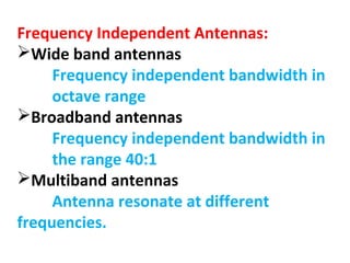


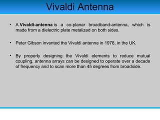
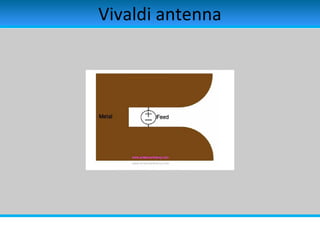


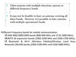


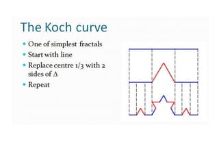


The document discusses various types of antennas, including frequency independent, wideband, broadband, multiband, and RFID antennas, highlighting their characteristics and design methods. It details the construction and operational principles of specific antennas like spiral and Vivaldi antennas, including their bandwidth enhancement techniques. Additionally, it outlines the frequency bands used in mobile communication and mentions different antenna structures and configurations such as fractal antennas.


