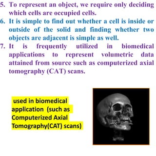
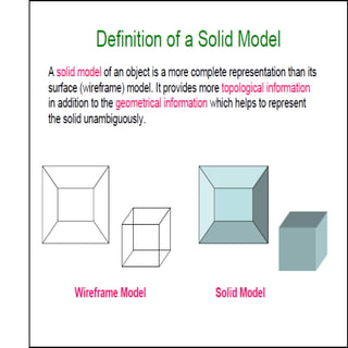
SOLID MODELING
schemes
UNIT-II -part-B
Solid Modelling:
Definition of cell composition and
spatial occupancy enumeration,
Sweep representation,
Constructive solid geometry,
Boundary representations.
1. Defines a set of primitive cells
2. Differs from primitive instancing(“Glue”
operation)
3. Unambiguous but not necessarily unique
4. Often used in biomedical application (such as
Computerized Axial Tomography(CAT) scans)
Cell-decomposition
1. In cell-decomposition, an object may be
represented as the addition of cells into which it
may be decomposed.
2. Each cell-decomposition system described a set
of primitive cells that are typically
parameterized and are frequently curved.
3. Cell-decomposition differs from primitive
instancing in that we may compose more
complicated objects from simple, primitive
ones as a bottom-up fashion by "gluing" them
together.
4. The glue operation may be thought of as a
limited form union in which the objects should
not intersect.
5. Further limitation on gluing cells frequently
require that two cells share a single point, edge,
or face.
6. Although cell-decomposition representation of
an object is unambiguous.
7. Cell-decompositions are also hard to validate,
as each pair of cells should potentially be tested
for intersection.
8. Cell-decomposition is significant for use in
finite element analysis.
Spatial-Occupancy Enumeration
1. This is a special case of cell-decomposition
in which the solid is decomposed in
identical cells arranged in a fixed regular
grid.
2. These cells are frequently called voxels
(volume elements), in analogy to pixels.
3. The most common cell type is the cube,
and the representation of space like a
regular array of cubes is called as
cuberile.
4. While representing an object by using
spatial-occupancy enumeration, only we
control the presence or absence of a single
cell at each of the position in the grid.
5. To represent an object, we require only deciding
which cells are occupied cells.
6. It is simple to find out whether a cell is inside or
outside of the solid and finding whether two
objects are adjacent is simple as well.
7. It is frequently utilized in biomedical
applications to represent volumetric data
attained from source such as computerized axial
tomography (CAT) scans.
used in biomedical
application (such as
Computerized Axial
Tomography(CAT) scans)
A series of voxels in a stack, with a
single voxel shaded
Wire Frame Model
•Oldest form of 3D modeling
•Old technology - not used
today
•Model Contains edges
and vertices
• Cannot represent complex
surfaces
•No details regarding interior
of part
•Ambiguous
Surface Model
•Came after Wireframe models
•Still used today
•Model Contains edges and
vertices and exterior surfaces
• Can represent complex
exterior surfaces
•No details regarding interior of
part
•Too ambiguous for engineering
analysis
Solid Model
•Model Contains
edges and vertices ,
exterior surfaces, and
interior details
•Part is
unambiguously
defined
•May be used for
engineering
analysis
Why Solid Modeling?
• Recall weakness of wireframe and surface
modeling
– Ambiguous or not clear geometric description
– incomplete geometric description
– lack topological information
– Tedious or too long modeling process
Solid model
• Solid modeling is based on complete, valid and
unambiguous
geometric representation of physical object.
– Complete → points in space can be
classified.(inside/outside)
– Valid →vertices, edges, faces are connected properly.
– Unambiguous → There can only be one
interpretation of object
• Analysis automation and integration is possible only with
solid models→ has properties such as weight, moment of
inertia, mass.
• Solid model consist of geometric and topological data
– Geometry → shape, size, location of geometric
elements
– Topology →connectivity and associatively of
geometric elements →non graphical, relational
information
P1907202034442303339991
Solid model representation schemes
1. Primitive instancing
2. Regularized Boolean set
operations
3. Sweep representations.
4. Boundary representations (B-reps)
5. Constructive solid geometry
(CSG)
6. Spatial-partitioning
representations
Primitives
Primitives in-use
Boundary representation (B-Rep)
1. Solid model is defined by their enclosing surfaces or
boundaries. This technique consists of the geometric
information about the faces, edges and vertices of an
object with the topological data on how these are
connected.
2. Why B-Rep includes such topological information?
1. A solid is represented as a closed space in 3D
space (surface connect without gaps)
2. The boundary of a solid separates points inside from
points outside solid.
3. B- Rep model
1. Technique guarantees that surfaces definitively
divide model space into solid and even after model
modification commands.
2. B-Rep graph store face, edge and vertices as
nodes, with pointers, or branches between the
nodes to indicate connectivity.
Boundary representation- validity
• System must validate topology of created solid.
• B-Rep has to fulfill certain conditions to disallow self-
intersecting and open objects
• This condition include
– Each edge should adjoin exactly two faces and have
a vertex at each end.
– Vertices are geometrically described by point
coordinates
– At least three edges must meet at each vertex.
– Faces are described by surface equations
– The set of faces forms a complete skin of the solid
with no missing parts.
– Each face is bordered by an ordered set of edges for
closed loop
– Faces must only intersect at common edges or
vertices.
– The boundaries of faces do not intersect themselves
B-Rep data structure
solid
f4
E3
E5
f5E2
E6
E7
E8
v1 v2
v3
f1
v5
f3 E4
f2
E1 v4
vertex1 vertex2vertex3vertex4vertex5
(x, y, z)
face1 face2 face3 face4 face5
Combinatorial
edge1 edge2 edge3 edge4 edge5 edge6 edge7 edge8 structure /
topology
Metric information/
geometry
• Valid B-Reps are unambiguous
• Not fully unique, but much more so than CSG
• Potential difference exists in division of
– Surfaces into faces.
– Curves into edges
• Capability to construct unusual shapes that would
not be possible with the available CSG aircraft
fuselages, swing shapes
• Less computational time to reconstruct the image
• Requires more storage
• More prone to validity failure than CSG
• Model display limited to planar faces and linear
edges
– complex curve and surfaces only approximated
Boundary representation-
ambiguity and uniqueness
Constructive Solid Geometry
Constructive solid geometry (CSG)
• Objects are represented as a combination of simpler
solid objects (primitives).
• The primitives are such as cube, cylinder, cone, torus,
sphere etc.
• Copies or “instances” of these primitive shapes are
created and positioned.
• A complete solid model is constructed by combining these
“instances” using set specific, logic operations (Boolean)
• Boolean operation
– each primitive solid is assumed to be a set of points, a
boolean operation is performed on point sets and the
result is a solid model.
– Boolean operation 🡪 union, intersection and difference
– The relative location and orientation of the two
primitives have to
be defined before the boolean operation can be
performed.
– Boolean operation can be applied to two solids
other than the primitives.
Constructive Solid Geometry Methods
• Constructive Solid Geometry (CSG) performs
solid modelling by generating a new object from
two 3-dimensional objects using a set operation
• Valid set operations include
– Union
– Intersection
– Difference
CSG Operations
• Primitives:
• Union:
• Intersection:
• Difference:
Constructive Solid Geometry Methods
(cont…)
Constructive Solid Geometry Methods
(cont…)
• CSG usually starts with a small set of
primitives such as blocks, pyramids,
spheres and cones
• Two objects re initially created and
combined using some set operation to
create a new object
• This object can then be combined with
another primitive to make another new
object
• This process continues until
modelling complete
Constructive Solid Geometry Methods
(cont…)
CSG
Object
oper
1
obj1 obj2
oper
3
obj4
oper
2
obj2 obj3
• CSG models are
usually represented
as CSG trees
Constructive solid geometry
(CSG)- CSG tree
+
-
CSG Data Structure
• Type def struct _csgtree
– Operator op;
– Quadric primitive;
– struct _csgtree *right;
– struct _csgtree *left;
• } CSGTreePtr;
• Each leaf node represents a primitive (usually a
quadric primitive).
• ‘op’ can also be ‘leaf’ rather than a combination
operator.
• When using Boolean operation, be careful
to avoid situation that do not result in a
invalid solid
Constructive solid geometry (CSG)-
Boolean operation
A  B
A B
• Boolean operation
– Are intuitive to user
– Are easy to use and understand
– Provide for the rapid manipulation of large amounts of data.
• Because of this, many non-CSG systems also use Boolean operations
• Data structure does not define model shape explicitly but rather
implies the geometric shape through a procedural description
– E.g: object is not defined as a set of edges & faces but by the
instruction :
union primitive1 with primitive 2
• This procedural data is stored in a data structure referred to as a
CSG tree
• The data structure is simple and stores compact data easy to
manage
• CSG tree stores the history of applying boolean operations on the
primitives.
– Stores in a binary tree format
– The outer leaf nodes of tree represent the primitives
– The interior nodes represent the boolean operations performed.
Constructive Solid Geometry (CSG)- Boolean operation
Advantage
• CSG is powerful with high level command.
• Easy to construct a solid model – minimum step.
• CSG modeling techniques lead to a concise database less
storage.
– Complete history of model is retained and can be
altered at any point.
• Can be converted to the corresponding boundary
representation.
Disadvantage
• Only boolean operations are allowed in the modeling process
with boolean operation alone, the range of shapes to be
modeled is severely restricted not possible to construct
unusual shape.
• Requires a great deal of computation to derive the
information on the boundary, faces and edges which is
important for the interactive display/ manipulation of
solid.
Constructive Solid Geometry (CSG) –
Advantage and Disadvantage
Examples
www-2.cs.cmu.edu/afs/cs/misc/rayshade/
all_mach/omega/doc/Examples/jpg/csg.jp
g
ccvweb.csres.utexas.edu/ccv/projects/VisualEyes/
visualization/domainpara/algebraic2/parameterization/
gallery/Reconstruction/Csg/
Parameter Sweeps B-reps CSG Octree
Accuracy High
Sometimes
Requir
es
appro
x.
High High
Domain Limited
Can
Represent
wide class
of objects
Limited
to some
extend
Limited
Uniqueness Unique Unique Not Unique Unique
Validity
Easy to
Validate
Most difficult
to validate
Easy to
Validate
Easy to
Validate
Closure
Not
closed
under
Boolean
operatio
ns
May suffer
from closure
problems
under
Boolean
operations
Closed Closed
Compactness
More
Compact
and
efficient
Compact
and
evaluation
is not
necessary
More
Compact
needs
evaluation of
Boolean
operations
and
transformatio
n
Compact

SOLID MODELLING.pptx

  • 1.
  • 2.
    UNIT-II -part-B Solid Modelling: Definitionof cell composition and spatial occupancy enumeration, Sweep representation, Constructive solid geometry, Boundary representations.
  • 3.
    1. Defines aset of primitive cells 2. Differs from primitive instancing(“Glue” operation) 3. Unambiguous but not necessarily unique 4. Often used in biomedical application (such as Computerized Axial Tomography(CAT) scans)
  • 4.
    Cell-decomposition 1. In cell-decomposition,an object may be represented as the addition of cells into which it may be decomposed. 2. Each cell-decomposition system described a set of primitive cells that are typically parameterized and are frequently curved. 3. Cell-decomposition differs from primitive instancing in that we may compose more complicated objects from simple, primitive ones as a bottom-up fashion by "gluing" them together. 4. The glue operation may be thought of as a limited form union in which the objects should not intersect. 5. Further limitation on gluing cells frequently require that two cells share a single point, edge, or face.
  • 5.
    6. Although cell-decompositionrepresentation of an object is unambiguous. 7. Cell-decompositions are also hard to validate, as each pair of cells should potentially be tested for intersection. 8. Cell-decomposition is significant for use in finite element analysis.
  • 6.
    Spatial-Occupancy Enumeration 1. Thisis a special case of cell-decomposition in which the solid is decomposed in identical cells arranged in a fixed regular grid. 2. These cells are frequently called voxels (volume elements), in analogy to pixels. 3. The most common cell type is the cube, and the representation of space like a regular array of cubes is called as cuberile. 4. While representing an object by using spatial-occupancy enumeration, only we control the presence or absence of a single cell at each of the position in the grid.
  • 8.
    5. To representan object, we require only deciding which cells are occupied cells. 6. It is simple to find out whether a cell is inside or outside of the solid and finding whether two objects are adjacent is simple as well. 7. It is frequently utilized in biomedical applications to represent volumetric data attained from source such as computerized axial tomography (CAT) scans. used in biomedical application (such as Computerized Axial Tomography(CAT) scans)
  • 9.
    A series ofvoxels in a stack, with a single voxel shaded
  • 10.
    Wire Frame Model •Oldestform of 3D modeling •Old technology - not used today •Model Contains edges and vertices • Cannot represent complex surfaces •No details regarding interior of part •Ambiguous
  • 11.
    Surface Model •Came afterWireframe models •Still used today •Model Contains edges and vertices and exterior surfaces • Can represent complex exterior surfaces •No details regarding interior of part •Too ambiguous for engineering analysis
  • 12.
    Solid Model •Model Contains edgesand vertices , exterior surfaces, and interior details •Part is unambiguously defined •May be used for engineering analysis
  • 14.
    Why Solid Modeling? •Recall weakness of wireframe and surface modeling – Ambiguous or not clear geometric description – incomplete geometric description – lack topological information – Tedious or too long modeling process
  • 18.
    Solid model • Solidmodeling is based on complete, valid and unambiguous geometric representation of physical object. – Complete → points in space can be classified.(inside/outside) – Valid →vertices, edges, faces are connected properly. – Unambiguous → There can only be one interpretation of object • Analysis automation and integration is possible only with solid models→ has properties such as weight, moment of inertia, mass. • Solid model consist of geometric and topological data – Geometry → shape, size, location of geometric elements – Topology →connectivity and associatively of geometric elements →non graphical, relational information
  • 19.
  • 20.
    Solid model representationschemes 1. Primitive instancing 2. Regularized Boolean set operations 3. Sweep representations. 4. Boundary representations (B-reps) 5. Constructive solid geometry (CSG) 6. Spatial-partitioning representations
  • 21.
  • 22.
  • 38.
    Boundary representation (B-Rep) 1.Solid model is defined by their enclosing surfaces or boundaries. This technique consists of the geometric information about the faces, edges and vertices of an object with the topological data on how these are connected. 2. Why B-Rep includes such topological information? 1. A solid is represented as a closed space in 3D space (surface connect without gaps) 2. The boundary of a solid separates points inside from points outside solid. 3. B- Rep model 1. Technique guarantees that surfaces definitively divide model space into solid and even after model modification commands. 2. B-Rep graph store face, edge and vertices as nodes, with pointers, or branches between the nodes to indicate connectivity.
  • 39.
    Boundary representation- validity •System must validate topology of created solid. • B-Rep has to fulfill certain conditions to disallow self- intersecting and open objects • This condition include – Each edge should adjoin exactly two faces and have a vertex at each end. – Vertices are geometrically described by point coordinates – At least three edges must meet at each vertex. – Faces are described by surface equations – The set of faces forms a complete skin of the solid with no missing parts. – Each face is bordered by an ordered set of edges for closed loop – Faces must only intersect at common edges or vertices. – The boundaries of faces do not intersect themselves
  • 46.
    B-Rep data structure solid f4 E3 E5 f5E2 E6 E7 E8 v1v2 v3 f1 v5 f3 E4 f2 E1 v4 vertex1 vertex2vertex3vertex4vertex5 (x, y, z) face1 face2 face3 face4 face5 Combinatorial edge1 edge2 edge3 edge4 edge5 edge6 edge7 edge8 structure / topology Metric information/ geometry
  • 47.
    • Valid B-Repsare unambiguous • Not fully unique, but much more so than CSG • Potential difference exists in division of – Surfaces into faces. – Curves into edges • Capability to construct unusual shapes that would not be possible with the available CSG aircraft fuselages, swing shapes • Less computational time to reconstruct the image • Requires more storage • More prone to validity failure than CSG • Model display limited to planar faces and linear edges – complex curve and surfaces only approximated Boundary representation- ambiguity and uniqueness
  • 48.
  • 49.
    Constructive solid geometry(CSG) • Objects are represented as a combination of simpler solid objects (primitives). • The primitives are such as cube, cylinder, cone, torus, sphere etc. • Copies or “instances” of these primitive shapes are created and positioned. • A complete solid model is constructed by combining these “instances” using set specific, logic operations (Boolean) • Boolean operation – each primitive solid is assumed to be a set of points, a boolean operation is performed on point sets and the result is a solid model. – Boolean operation 🡪 union, intersection and difference – The relative location and orientation of the two primitives have to be defined before the boolean operation can be performed. – Boolean operation can be applied to two solids other than the primitives.
  • 50.
    Constructive Solid GeometryMethods • Constructive Solid Geometry (CSG) performs solid modelling by generating a new object from two 3-dimensional objects using a set operation • Valid set operations include – Union – Intersection – Difference
  • 51.
    CSG Operations • Primitives: •Union: • Intersection: • Difference:
  • 52.
    Constructive Solid GeometryMethods (cont…)
  • 53.
    Constructive Solid GeometryMethods (cont…) • CSG usually starts with a small set of primitives such as blocks, pyramids, spheres and cones • Two objects re initially created and combined using some set operation to create a new object • This object can then be combined with another primitive to make another new object • This process continues until modelling complete
  • 54.
    Constructive Solid GeometryMethods (cont…) CSG Object oper 1 obj1 obj2 oper 3 obj4 oper 2 obj2 obj3 • CSG models are usually represented as CSG trees
  • 56.
  • 57.
    CSG Data Structure •Type def struct _csgtree – Operator op; – Quadric primitive; – struct _csgtree *right; – struct _csgtree *left; • } CSGTreePtr; • Each leaf node represents a primitive (usually a quadric primitive). • ‘op’ can also be ‘leaf’ rather than a combination operator.
  • 58.
    • When usingBoolean operation, be careful to avoid situation that do not result in a invalid solid Constructive solid geometry (CSG)- Boolean operation A  B A B
  • 59.
    • Boolean operation –Are intuitive to user – Are easy to use and understand – Provide for the rapid manipulation of large amounts of data. • Because of this, many non-CSG systems also use Boolean operations • Data structure does not define model shape explicitly but rather implies the geometric shape through a procedural description – E.g: object is not defined as a set of edges & faces but by the instruction : union primitive1 with primitive 2 • This procedural data is stored in a data structure referred to as a CSG tree • The data structure is simple and stores compact data easy to manage • CSG tree stores the history of applying boolean operations on the primitives. – Stores in a binary tree format – The outer leaf nodes of tree represent the primitives – The interior nodes represent the boolean operations performed. Constructive Solid Geometry (CSG)- Boolean operation
  • 60.
    Advantage • CSG ispowerful with high level command. • Easy to construct a solid model – minimum step. • CSG modeling techniques lead to a concise database less storage. – Complete history of model is retained and can be altered at any point. • Can be converted to the corresponding boundary representation. Disadvantage • Only boolean operations are allowed in the modeling process with boolean operation alone, the range of shapes to be modeled is severely restricted not possible to construct unusual shape. • Requires a great deal of computation to derive the information on the boundary, faces and edges which is important for the interactive display/ manipulation of solid. Constructive Solid Geometry (CSG) – Advantage and Disadvantage
  • 61.
  • 62.
    Parameter Sweeps B-repsCSG Octree Accuracy High Sometimes Requir es appro x. High High Domain Limited Can Represent wide class of objects Limited to some extend Limited Uniqueness Unique Unique Not Unique Unique Validity Easy to Validate Most difficult to validate Easy to Validate Easy to Validate Closure Not closed under Boolean operatio ns May suffer from closure problems under Boolean operations Closed Closed Compactness More Compact and efficient Compact and evaluation is not necessary More Compact needs evaluation of Boolean operations and transformatio n Compact