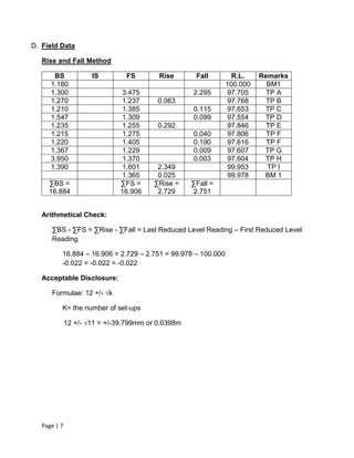
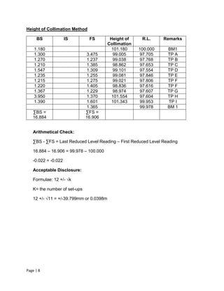
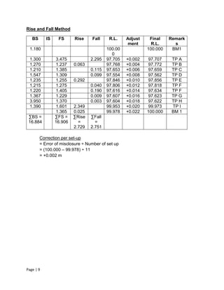
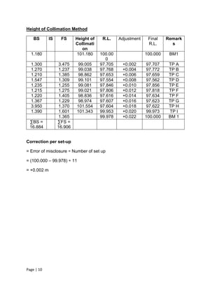
slides CapTechTalks Webinar May 2024 Alexander Perry.pptx
Site Surveying Levelling
1. Page | 1
SCHOOL OF ARCHITECTURE, BUILDING AND
DESIGN
BACHELOR OF QUANTITY SURVEYING (HONOURS)
QSB 60103- SITE SURVEYING
Fieldwork 1 Report
Levelling
Name Student ID Marks
LEE KIM THIAM 0310710
LEE CHUN YEE 0321748
LEE PEI GIE 0315653
LEE KIT HUNG 0315722
2. Page | 2
Table of Content
Content Page
Cover Page 1
Table of Content 2
A. Introduction to Levelling 3-4
B. Outline of Apparatus 5
i) Automatic Level 5
ii) Adjustable Leg-Tripod 5
iii) Optical Plummet 5
iv) Horizontal Bubble Level 6
v) Bar- Coded Level Rod 6
C. Objectives 6
D. Field Data 7 – 10
i) Rise and Fall Method 8 – 10
ii) Height of Collimation Method 9 – 10
E. Conclusion 11
3. Page | 3
A. Introduction to Leveling
Leveling is the process of measuring heights. It is possible when leveling to measure
heights with an accuracy of millimeters. Heights can also be measured using total
stations, handheld lasers and GPS devices. However, leveling offers an inexpensive,
simple and accurate method for measuring heights, and it is widely used in construction
sites. Any method of measuring the heights of points above or below the ground is done
by using an agreed datum. These datums or reference points are present in all
construction sites and has an arbitrary height assigned to the point. Most construction
sites will have several of these benchmarks, and if they have heights based on an
arbitrary datum, they are known as Temporary Bench Marks.
A horizontal line (or plane) of sight (line or plane of collimation) is established with a
telescope (fitted with cross-hairs) which can be turned about a vertical axis. The
difference in consecutive readings taken on a vertical staff gives the level difference
between two points as shown in Figure 1.
Figure 1: Leveling
(Source : http://www.colorado.edu/geography/courses/geog_2043_f01/lab4/diff.jpg)
4. Page | 4
There are 2 main methods of booking levels:
A) Rise and Fall Method B) Height of Collimation Method
Source :
(http://admin.i4learnprod.co.uk/repository/resource/view_resour
ce.php?id=122)
Source :
(http://gmba-learning-gateway.co.uk/images/Height_of_Col.jpg?713)
Definitions
Leveling : A surveying operation carried out to determine the elevation of points or to
find the difference in elevation of points.
Spirit level/Engineer’s Level : A surveying instrument used to carry out leveling.
Backsight (BS) : A sighting with a level back to a point of known elevation.
Foresight (FS) : A sighting with a level to determine the elevation of a point.
Intermediate Sight (IS) : A fore shot to a point at which you want to know the
elevation but which will not be used as a turning point.
Turning Point : A point at which you have established an elevation with FS and on
which you will subsequently take a BS.
Peg test : Surveying operation carried out to determine id the leveling bubble and
telescope line-of-sight are parallel.
Elevation of Instrument (EI) : Elevation of the telescope cross-hairs.
Balancing shots : attempt when doing a leveling survey to keep the lengths of FS
and BS at any given instrument setup as close as possible.
Closure Error : Difference in elevation determined from the leveling survey and the
known elevation of a benchmark.
5. Page | 5
B. Outline of Apparatus
1. Automatic Level
2. Adjustable Leg Tripod
3. Optical Plummet
Source :
(http://img.diytrade.com/cdimg/636179/4720826/0/1195520062/32
X_automatic_level.jpg )
A Professional Leveling Tool used by Contractors, Buildersm Land
Surveying Professionals, or the Engineer who demands accurate
leveling every time ( Tngineering Supply, 2014).
Source :
(http://www.vsaservicesindia.com/images/products/accessories/larg
e/1.jpg )
Adjustable-leg tripods is easy to set up on ground because each leg
can be adjusted to exactly the height needed to find level, even on a
steep slope (Johnson Level,2010).
Source :
(http://www.hayesinstrument.com/accs_TopconTribrachOP.jpg )
A device on some transits and theodolites; used to center the
instrument over a point, in place of a plumb bob, which moves in a
strong wind. (McGraw-Hill,2003).
6. Page | 6
4. Horizontal Bubble Level
5. Bar-Coded level Rod
C. Objectives
1. To enable students to get hands-on experience in setting up the working with the
auto-level.
2. To determine the error of disclosure in order to determine whether the leveling is
acceptable.
3. To allow students to apply theories learnt in classes in a hands-on situation such
as making adjustments for each reduced level of every single staff station in
order to obtain the most accurate reduced levels.
4. To identify the reduced level of each station.
5. To enhance students’ knowledge on leveling procedure.
Source : (http://cms.leica-
geosystems.us/wp/ape/files/2013/10/tribrach-components-3.jpg )
A tool to determine whether the surface is horizontal.
Source : (http://www.a1-
equipment.co.uk/uploaded/public/504a08e7b04253.41472947.jpg )
To determine the relative heights of the different points in the area
under survey (Clancy,1991).
7. Page | 7
D. Field Data
Rise and Fall Method
BS IS FS Rise Fall R.L. Remarks
1.180 100.000 BM1
1.300 3.475 2.295 97.705 TP A
1.270 1.237 0.063 97.768 TP B
1.210 1.385 0.115 97.653 TP C
1.547 1.309 0.099 97.554 TP D
1.235 1.255 0.292 97.846 TP E
1.215 1.275 0.040 97.806 TP F
1.220 1.405 0.190 97.616 TP F
1.367 1.229 0.009 97.607 TP G
3.950 1.370 0.003 97.604 TP H
1.390 1.601 2.349 99.953 TP I
1.365 0.025 99.978 BM 1
∑BS =
16.884
∑FS =
16.906
∑Rise =
2.729
∑Fall =
2.751
Arithmetical Check:
∑BS - ∑FS = ∑Rise - ∑Fall = Last Reduced Level Reading – First Reduced Level
Reading
16.884 – 16.906 = 2.729 – 2.751 = 99.978 – 100.000
-0.022 = -0.022 = -0.022
Acceptable Disclosure:
Formulae: 12 +/- √k
K= the number of set-ups
12 +/- √11 = +/-39.799mm or 0.0398m
8. Page | 8
Height of Collimation Method
BS IS FS Height of
Collimation
R.L. Remarks
1.180 101.180 100.000 BM1
1.300 3.475 99.005 97.705 TP A
1.270 1.237 99.038 97.768 TP B
1.210 1.385 98.862 97.653 TP C
1.547 1.309 99.101 97.554 TP D
1.235 1.255 99.081 97.846 TP E
1.215 1.275 99.021 97.806 TP F
1.220 1.405 98.836 97.616 TP F
1.367 1.229 98.974 97.607 TP G
3.950 1.370 101.554 97.604 TP H
1.390 1.601 101.343 99.953 TP I
1.365 99.978 BM 1
∑BS =
16.884
∑FS =
16.906
Arithmetical Check:
∑BS - ∑FS = Last Reduced Level Reading – First Reduced Level Reading
16.884 – 16.906 = 99.978 – 100.000
-0.022 = -0.022
Acceptable Disclosure:
Formulae: 12 +/- √k
K= the number of set-ups
12 +/- √11 = +/-39.799mm or 0.0398m
9. Page | 9
Rise and Fall Method
BS IS FS Rise Fall R.L. Adjust
ment
Final
R.L.
Remark
s
1.180 100.00
0
100.000 BM1
1.300 3.475 2.295 97.705 +0.002 97.707 TP A
1.270 1.237 0.063 97.768 +0.004 97.772 TP B
1.210 1.385 0.115 97.653 +0.006 97.659 TP C
1.547 1.309 0.099 97.554 +0.008 97.562 TP D
1.235 1.255 0.292 97.846 +0.010 97.856 TP E
1.215 1.275 0.040 97.806 +0.012 97.818 TP F
1.220 1.405 0.190 97.616 +0.014 97.634 TP F
1.367 1.229 0.009 97.607 +0.016 97.623 TP G
3.950 1.370 0.003 97.604 +0.018 97.622 TP H
1.390 1.601 2.349 99.953 +0.020 99.973 TP I
1.365 0.025 99.978 +0.022 100.000 BM 1
∑BS =
16.884
∑FS =
16.906
∑Rise
=
2.729
∑Fall
=
2.751
Correction per set-up
= Error of misclosure ÷ Number of set up
= (100.000 – 99.978) ÷ 11
= +0.002 m
10. Page | 10
Height of Collimation Method
BS IS FS Height of
Collimati
on
R.L. Adjustment Final
R.L.
Remark
s
1.180 101.180 100.00
0
100.000 BM1
1.300 3.475 99.005 97.705 +0.002 97.707 TP A
1.270 1.237 99.038 97.768 +0.004 97.772 TP B
1.210 1.385 98.862 97.653 +0.006 97.659 TP C
1.547 1.309 99.101 97.554 +0.008 97.562 TP D
1.235 1.255 99.081 97.846 +0.010 97.856 TP E
1.215 1.275 99.021 97.806 +0.012 97.818 TP F
1.220 1.405 98.836 97.616 +0.014 97.634 TP F
1.367 1.229 98.974 97.607 +0.016 97.623 TP G
3.950 1.370 101.554 97.604 +0.018 97.622 TP H
1.390 1.601 101.343 99.953 +0.020 99.973 TP I
1.365 99.978 +0.022 100.000 BM 1
∑BS =
16.884
∑FS =
16.906
Correction per set-up
= Error of misclosure ÷ Number of set up
= (100.000 – 99.978) ÷ 11
= +0.002 m
11. Page | 11
E. Conclusion
In this fieldwork, the reduced level of Bench Mark (BM) 1 is given which is 100.00m. The
leveling process begins with obtaining the backsight (BS) of BM1 and the foresight (FS) of
turning point (TP) A. Then the auto level is shifted to obtain the BS of TP A and the FS of TP B.
This process is repeated by shifting the auto level to obtain the BS and FS of the following staff
stations and lastly go back to BM1 to obtain its FS in order to calculate the error of misclosure.
We used both the rise and fall method and the height of collimation method to calculate the
reduced level of each staff station. The error of misclosure was -0.022mm and the acceptable
range of error of misclosure was calculated using the 12+/- √k formulae where k represents the
number of set-ups, and the acceptable range of error of
misclosure is +/- 39.799mm or +/- 0.0398m. Thus, our leveling is acceptable.
To distribute the error, the correction per set-up is calculated using the following formulae:
Correction per set-up:
= Error of misclosure ÷ Number of set up
The correction per-set up is +0.002m and is cumulative as shown in the table provided in
the adjusted data section.