Downloaded 734 times
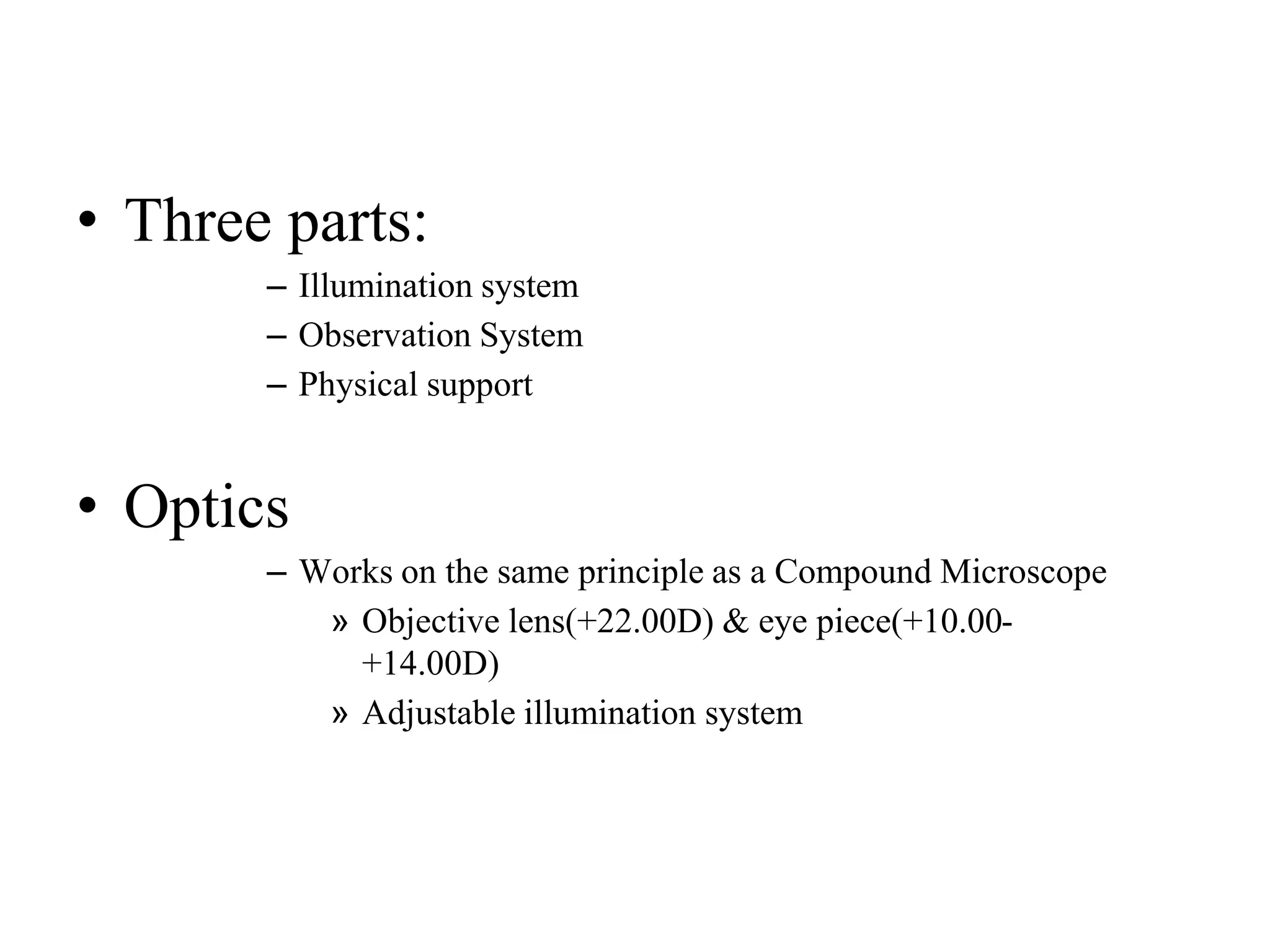

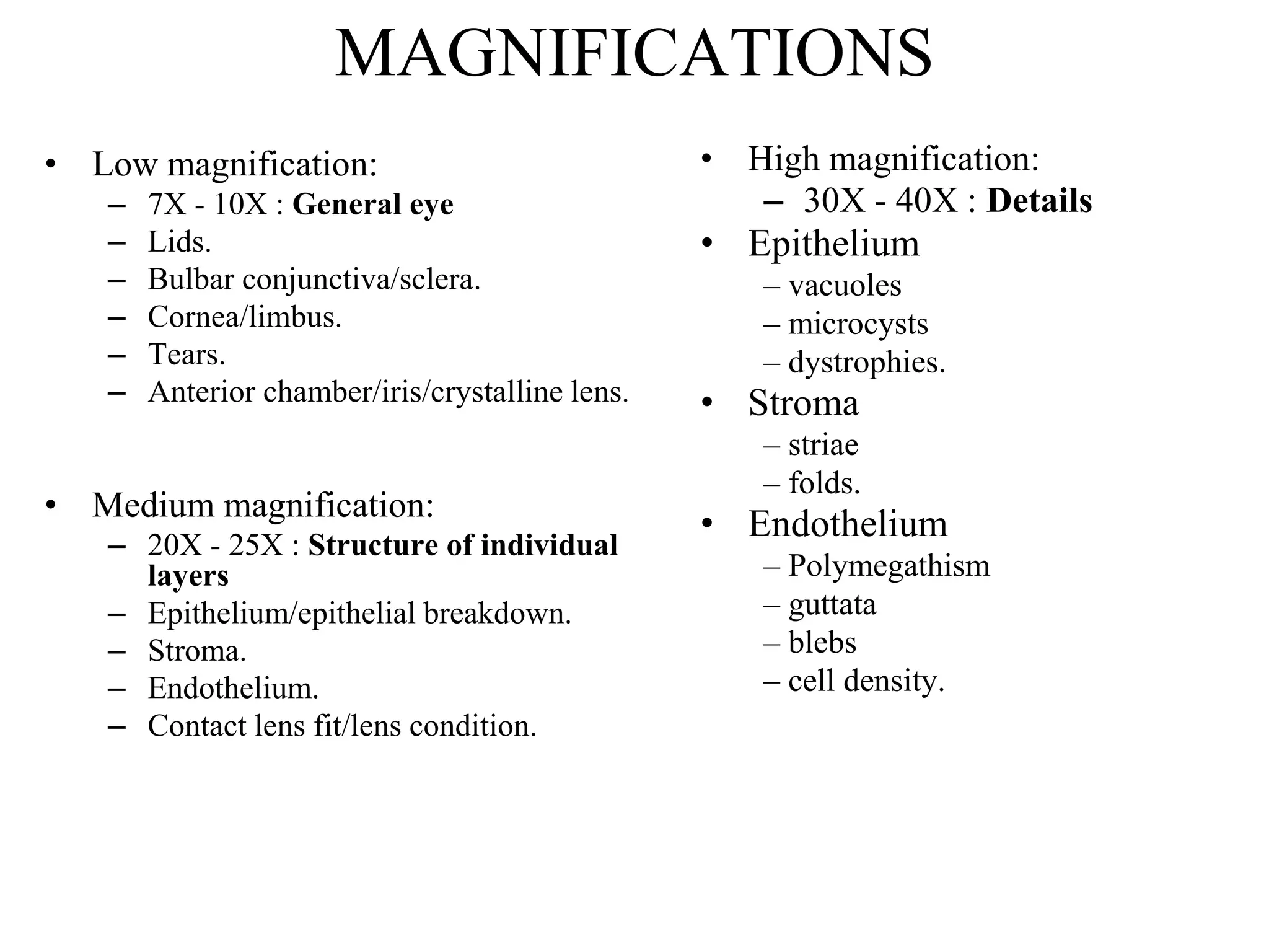
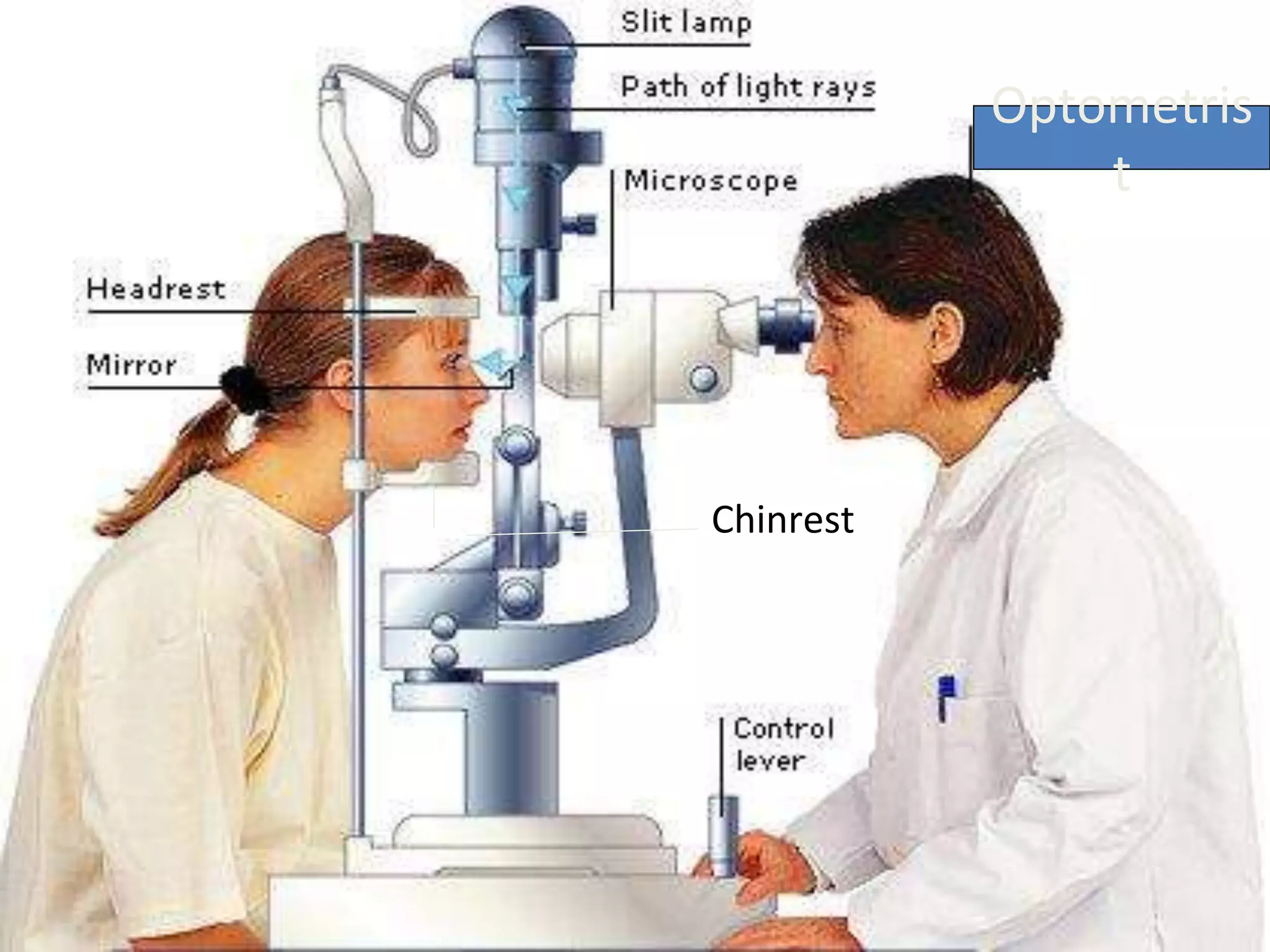


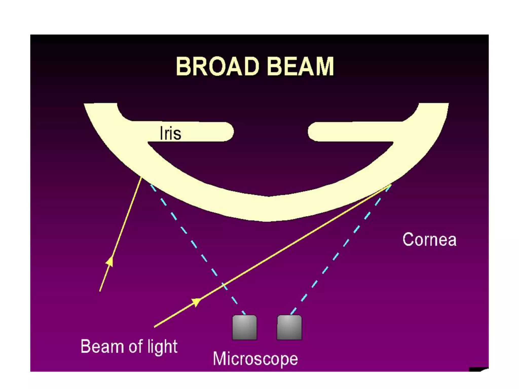

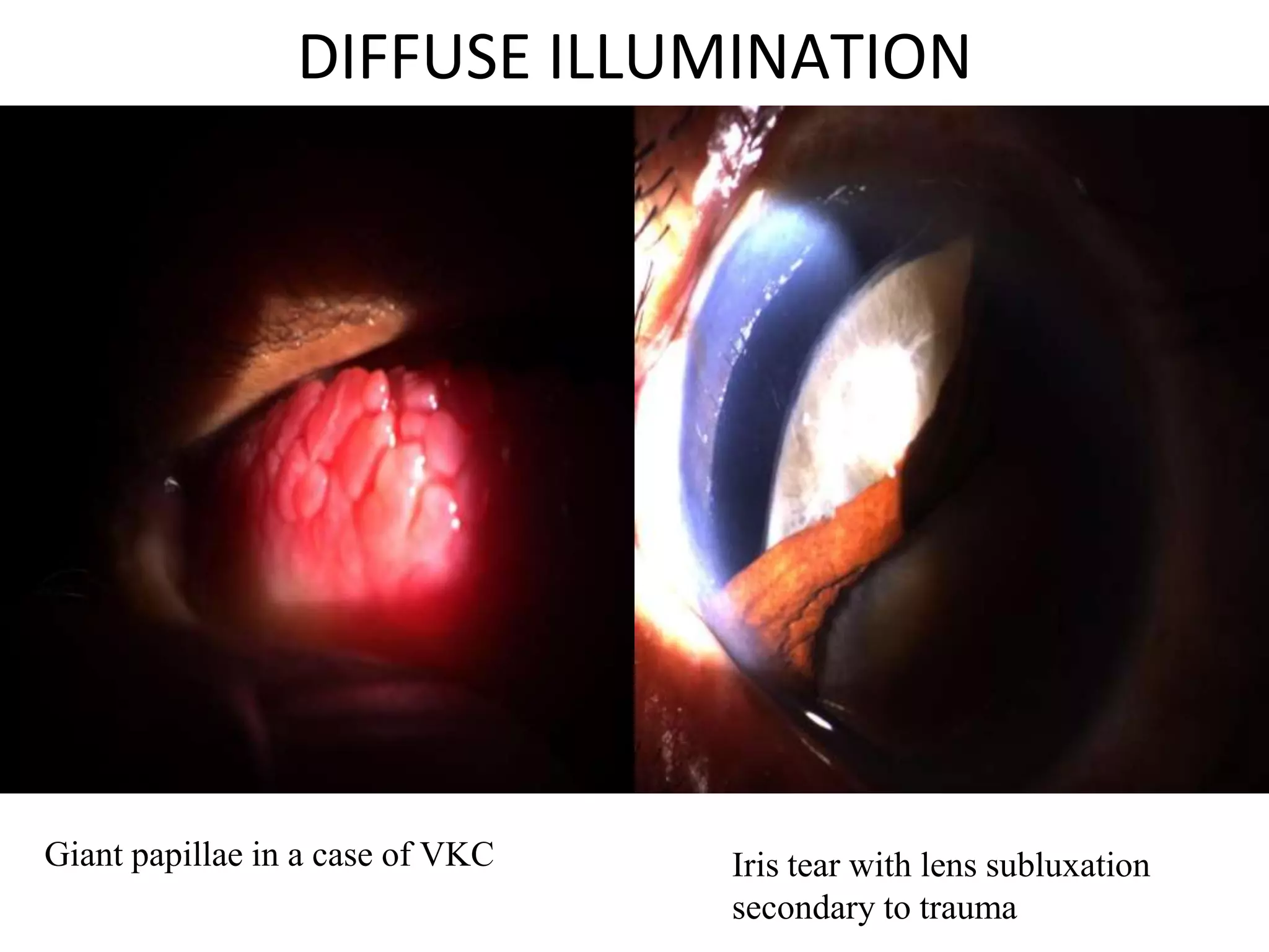
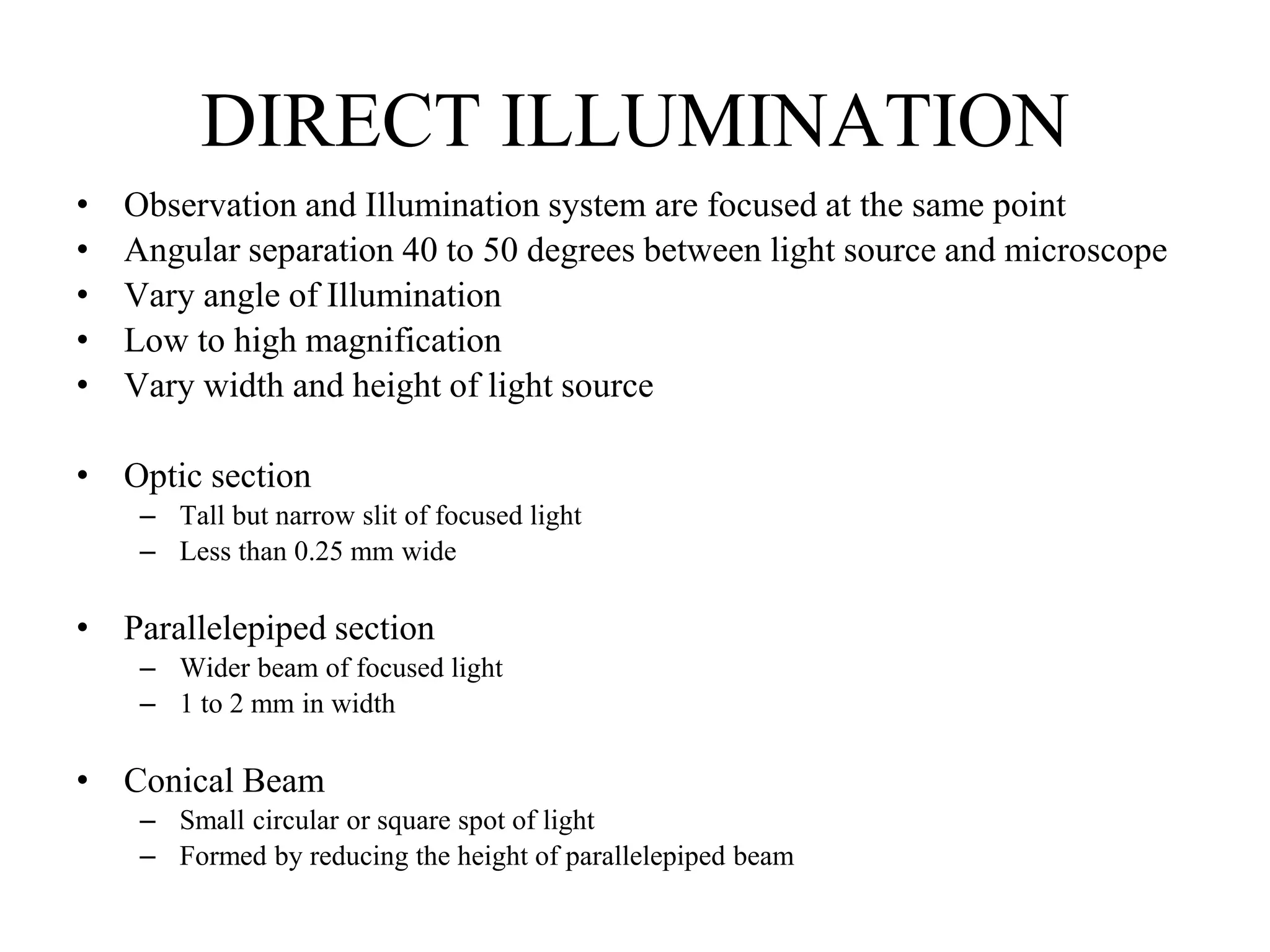
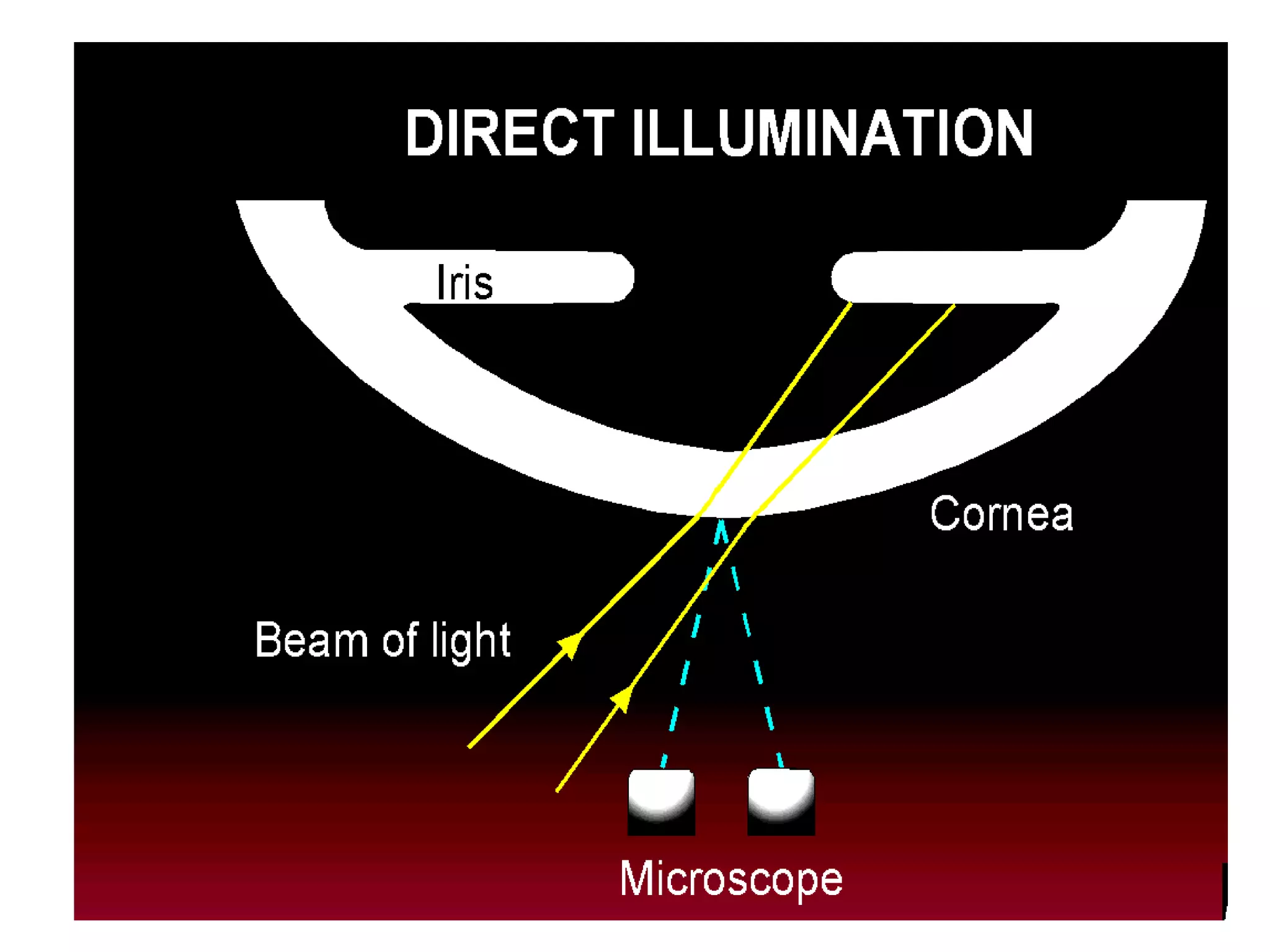


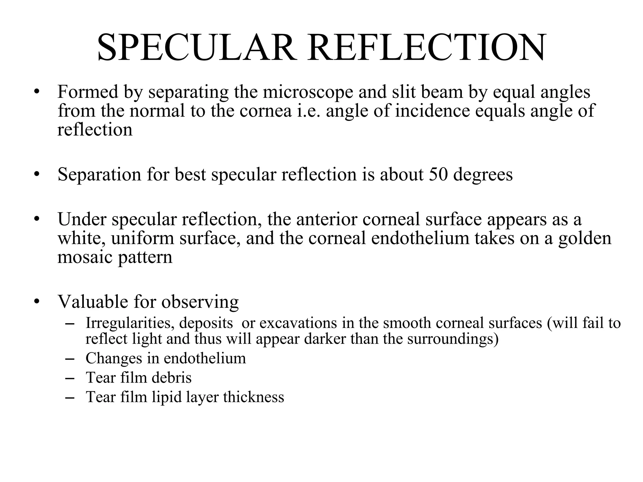


The document provides a detailed overview of slit lamp biomicroscopy, including its history, components, and operational techniques for examining the anterior segment of the eye. It outlines various illumination techniques such as diffuse, direct, and retro illumination, each suited for specific observations, and discusses magnification settings for different eye features. Additionally, it covers clinical uses and procedures for contact lens fitting using the slit lamp, emphasizing the importance of proper illumination and magnification for accurate diagnosis and treatment.


