Downloaded 189 times
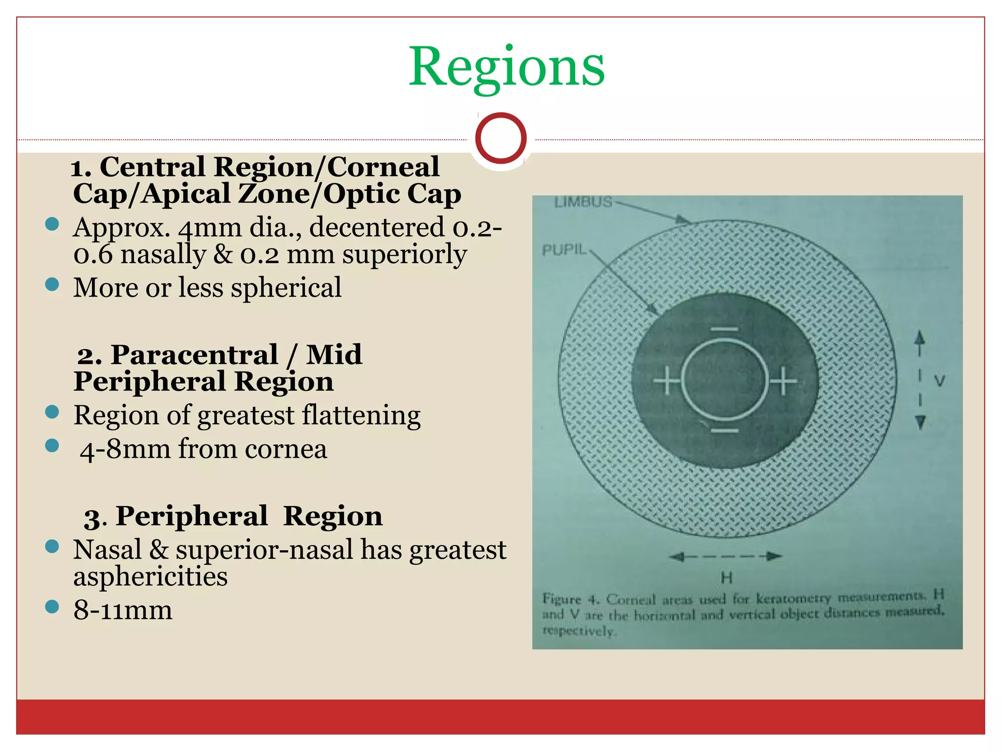
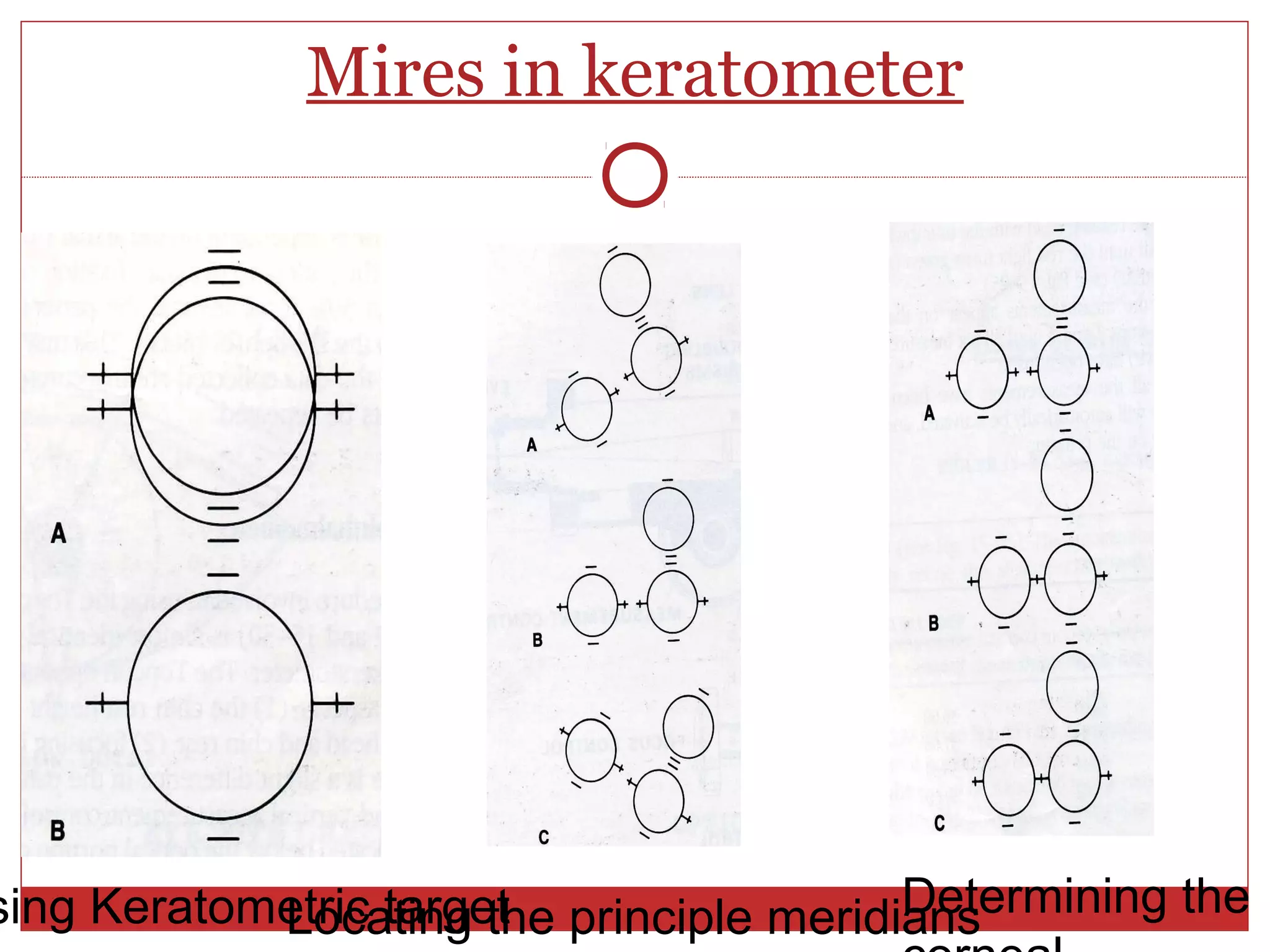
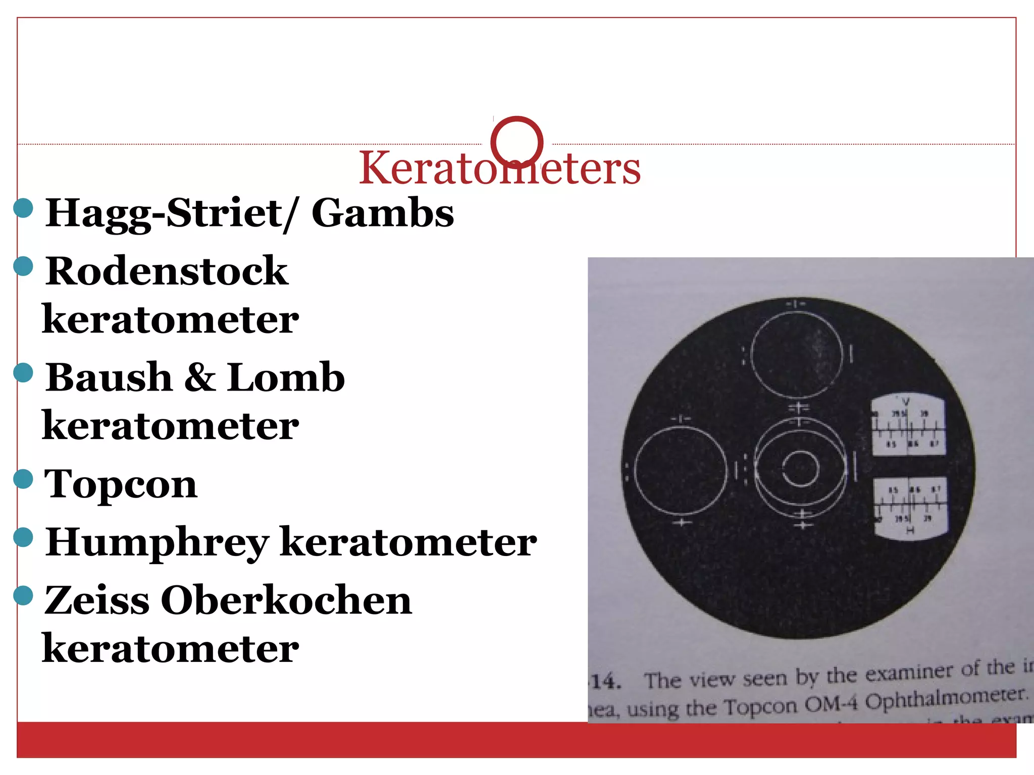
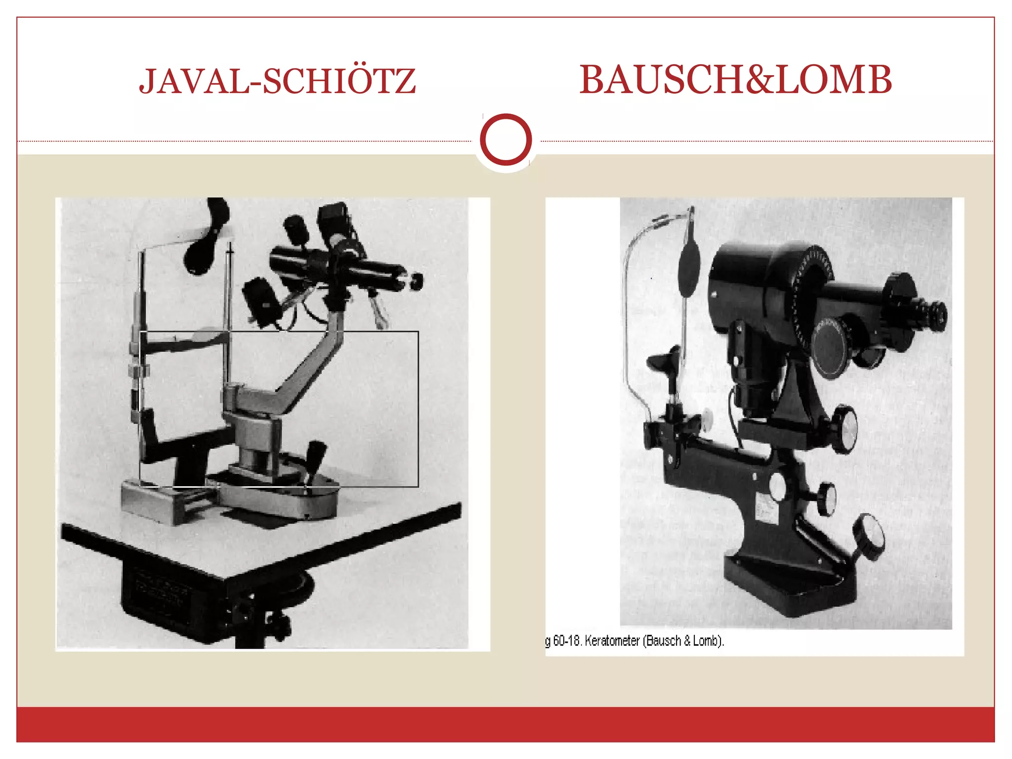
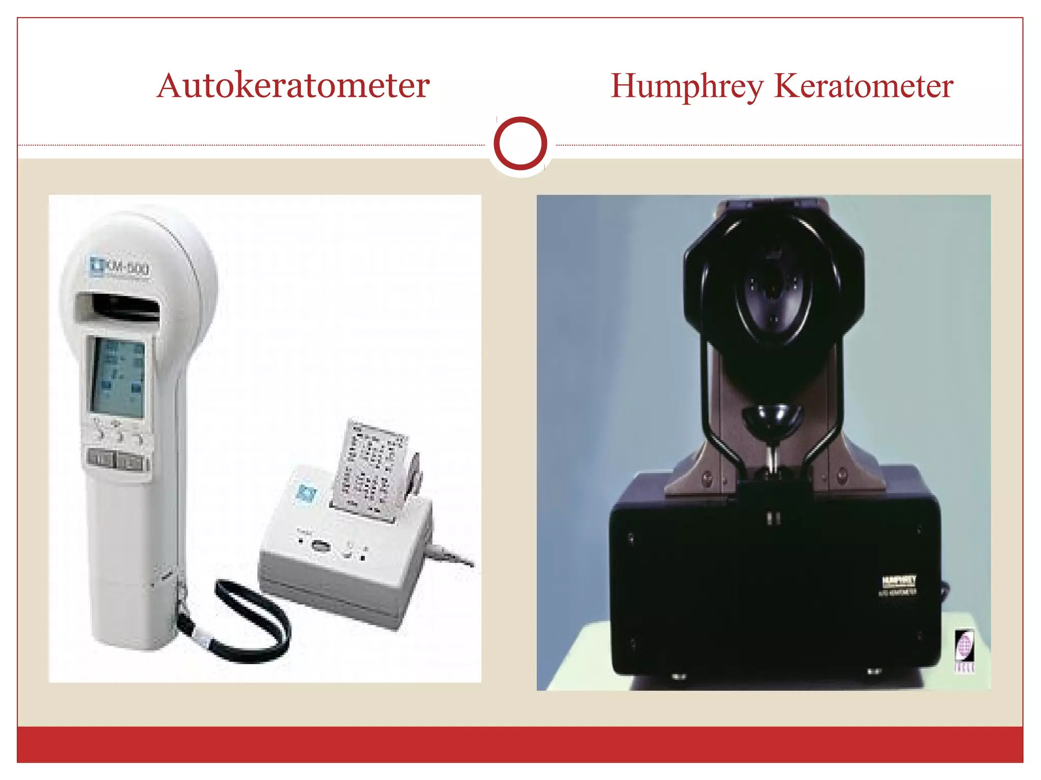
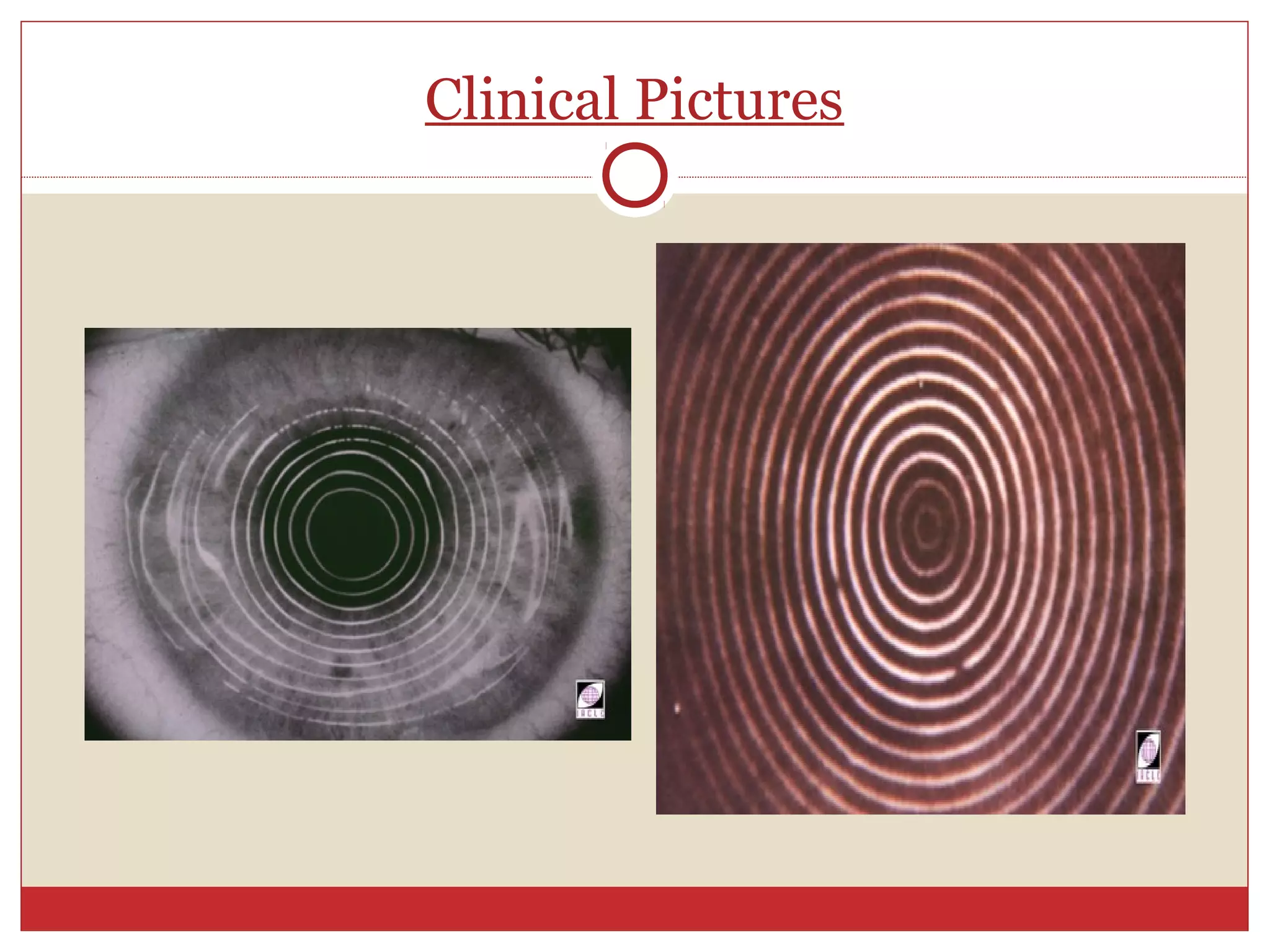
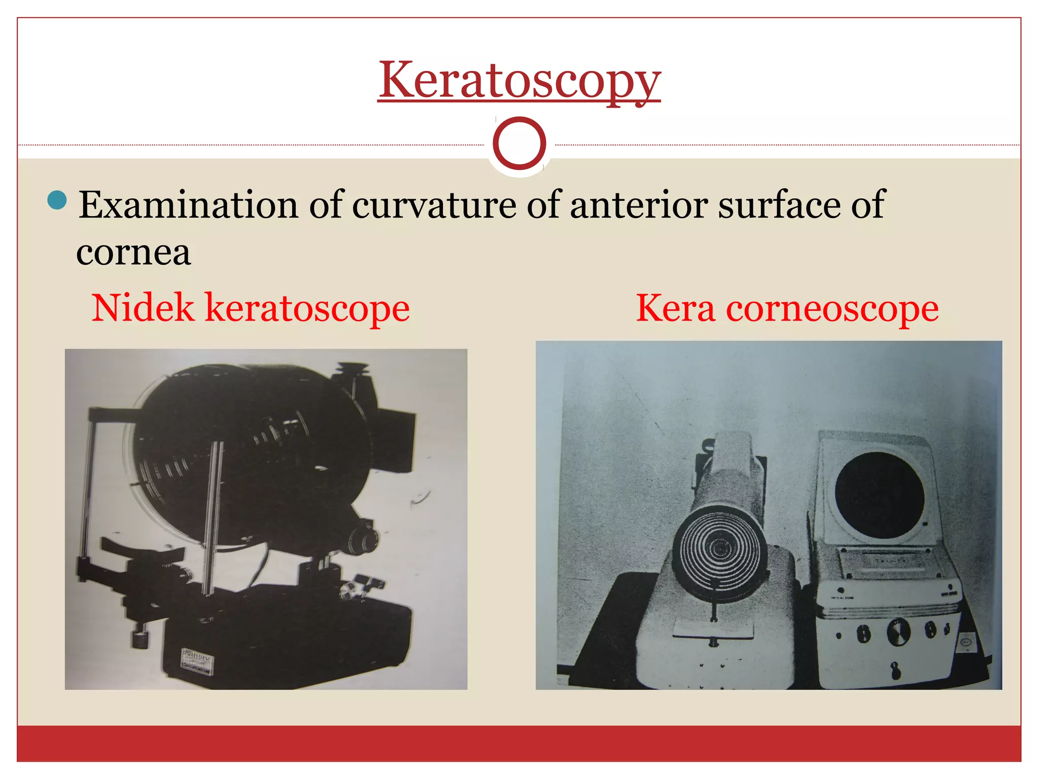
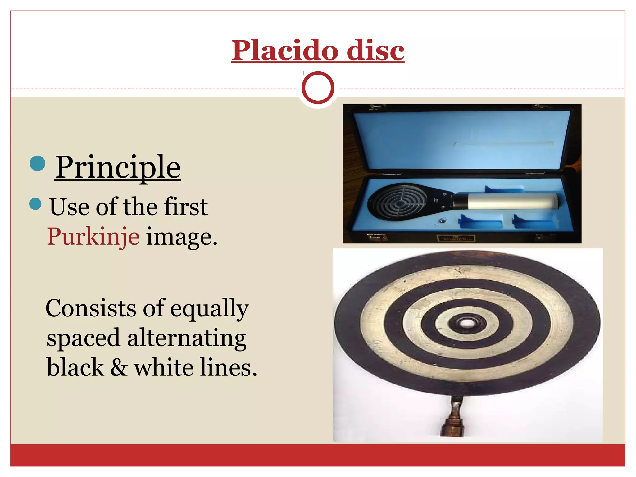


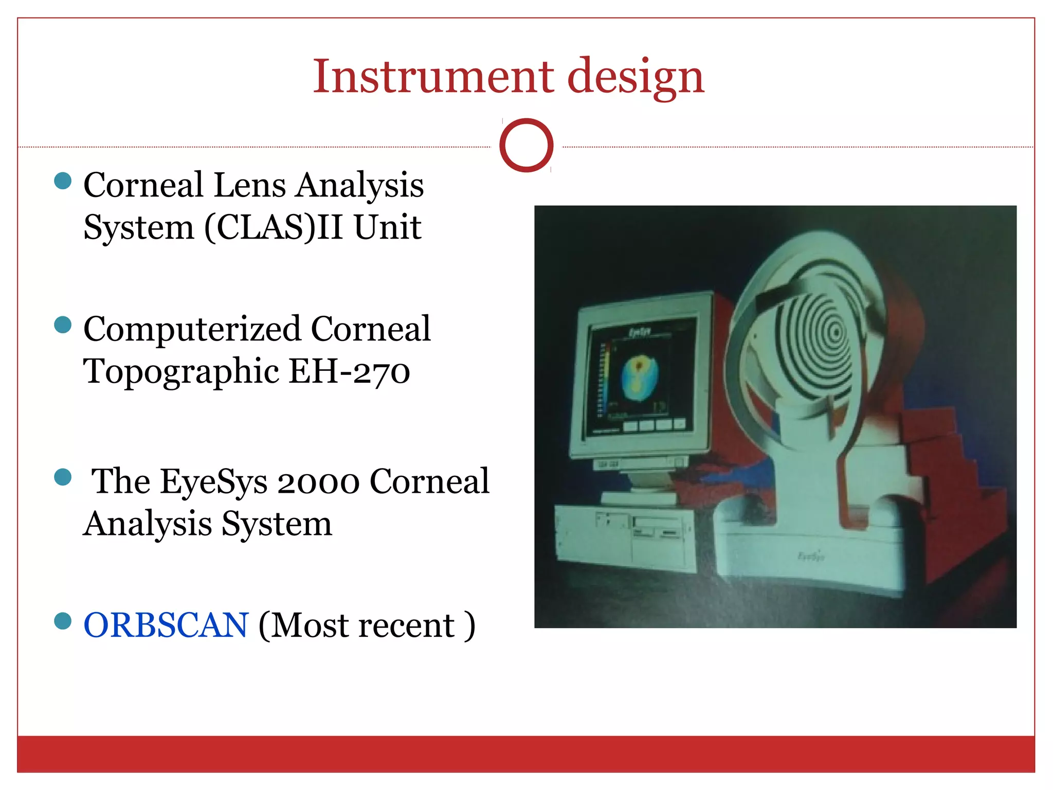


The document discusses corneal topography, a non-invasive imaging technique used for mapping corneal curvature, which aids in diagnosing and treating various eye conditions. It outlines the structure of the cornea, the mechanisms of keratometry and keratoscopy, and their applications in eye surgeries, contact lens fitting, and monitoring corneal pathologies. Additionally, it addresses the limitations and advancements in corneal analysis technologies for assessing corneal health and irregularities.


![Apporach to lung biopsy [Auto-saved].pptx latest](https://cdn.slidesharecdn.com/ss_thumbnails/apporachtolungbiopsyauto-saved-251211225655-93258539-thumbnail.jpg?width=640&height=640&fit=bounds)


