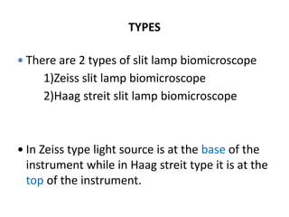
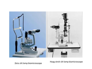
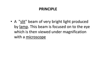
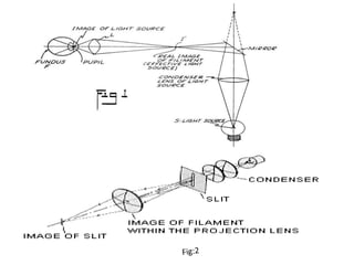
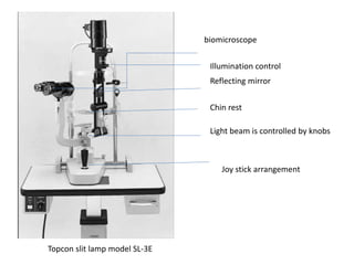
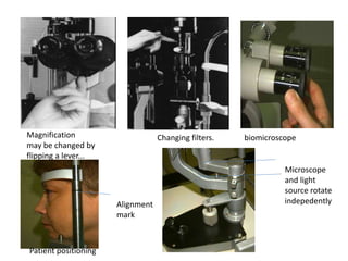
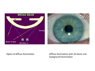
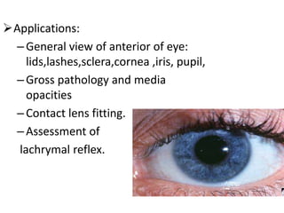
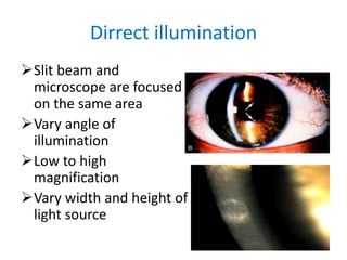
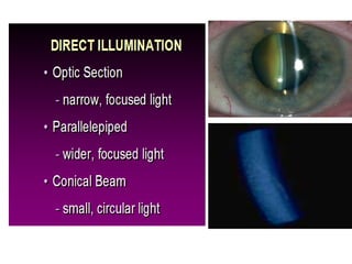
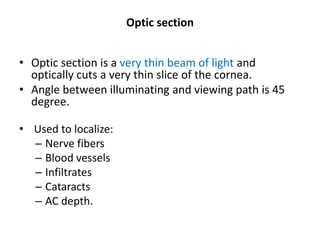
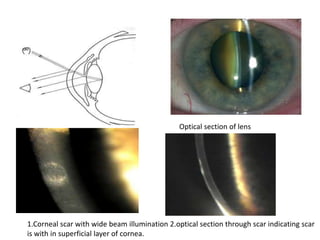
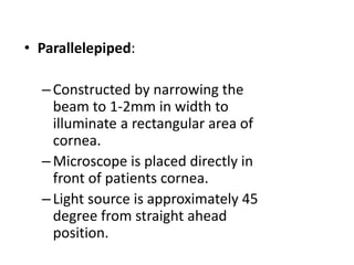
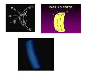
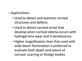
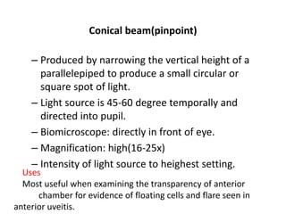
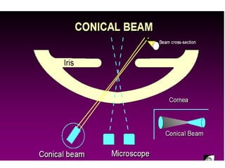
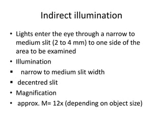
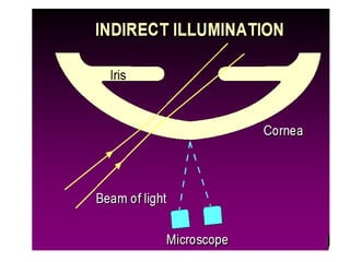
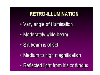
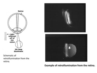
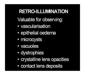
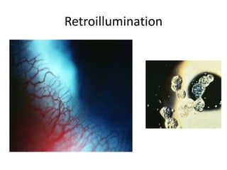
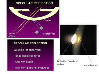
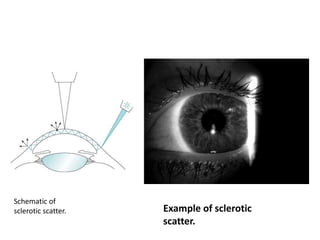
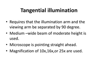
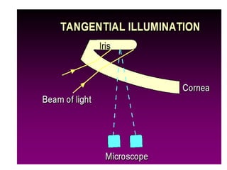
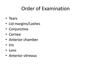
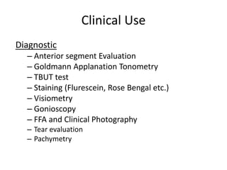
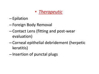
Md. Didarul alam
2nd year
B. Optom,ICO,CU
Slit lamp Biomicroscopy
optometrist
Introduction
• Biomicroscope derives its name from the fact
that it enables the clinician to observe the
living tissue of eye under magnification.
• It not only provides magnified view of every
part of eye but also allows quantitative
measurements and photography of every part
for documentation.
Important historical landmarks
• De Wecker 1863 devised a portable
ophthalmomicroscope .
• Albert and Greenough 1891,developed a binocular
microscope which provided stereoscopic view.
• Gullstrand ,1911 introduced the
illumination system which had for the
first time a slit diapharm in it
– Therefore Gullstrand is credited with the
invention of slit lamp.
Large Gullstrand
Ophthalmomicroscope
(1911)
TYPES
 There are 2 types of slit lamp biomicroscope
1)Zeiss slit lamp biomicroscope
2)Haag streit slit lamp biomicroscope
 In Zeiss type light source is at the base of the
instrument while in Haag streit type it is at the
top of the instrument.
Zeiss slit lamp biomicroscope
Haag streit slit lamp biomicroscope
PRINCIPLE
• A "slit" beam of very bright light produced
by lamp. This beam is focused on to the eye
which is then viewed under magnification
with a microscope
Topcon slit lamp model SL-3E
Light beam is controlled by knobs
Joy stick arrangement
Chin rest
Reflecting mirror
biomicroscope
Illumination control
Magnification
may be changed by
flipping a lever...
Changing filters. biomicroscope
Patient positioning
Alignment
mark
Microscope
and light
source rotate
indepedently
Instrumentation
• Operational components of slit lamp
biomicroscope essentially consist of:
–Illumination system
–Observation system
–Mechanical system
• Illumination system
• It consist of:
A bright ,focal source of light with a slit
mechanism
• Provides an illumination of 2*10^5 to 4*10^5
lux.
• The beam of light can be changed in
intensity,height,width,direction or angle and
color during the examination with the flick of
lever.
Condensing lens system:
–Consist of a couple of planoconvex lenses
with their convex surface in apposition.
Slit and other diapharm:
Height and width of slit can be varied by
using knobs.
The illumination and observation systems
coupled around a common centre of
rotation to ensure that the microscope is
always focused at the same point as where
the slit beam is focused.
Observation system(microscope)
 Observation system is composed of two
optical elements
1.an objective ,2.an eyepiece
 It presents to the observer an enlarged
image of a near object.
 The objective lens consists of two
planoconvex lenses facing towards the
patient
providing a composite power of +22D.
 Microscope is binocular i.e. it has two
eyepieces giving binocular observer a
sterescopic view of eye.
• The eye piece has a lens of +10D to + 14D
towards the examiner.
• To overcome the problem of inverted image
produced by compound microscope ,slit lamp
microscope uses a pair of prisms b/w the
objective and eyepiece to reinvert the image.
• Most slit lamp provide a range of
magnification from 6x to 40x
Mechanical/Physical support
• A joystick control is employed to enable
instrument to be moved left-right/forward-
backward (= focus)/ and up-down.
• A chin rest, head rest and fixation target is also
required. Some slit lamps have a tilting
mechanism to enable the lamp to be directed
from different angles.
– Used in conjunction with fluorescein stain
– absorbs blue light and emits green with
fluorescein stain.
 Uses:
• Ocular staining
• RGP lenses fitting
• Tear layer
Continue……..
 Obscure any thing that is red hence the red free
light , thus blood vessels or haemorrhages
appears black.
• is used to see the vascular pattern of choroid and
see any abnormalities in the disc of fundus.
• Fleischer ring can also be viewed satisfactorily with the
red FREE filter
• Yellow filter is used for general view of anterior segment.
Illumination techniques
– Diffuse illumination
– Direct illumination
• Parallilepiped
• Optic section
• Conical(pinpoint)
• Tangential
• Specular reflection
– Indirect illumination
• Retro-illumination
• Sclerotic scatter
• Transillumination
Diffuse illumination
• Angle between microscope and illumination
system should be 30-45 degree.
• Slit width should be widest.
• Filter to be used is diffusing filter.
• Magnification: low to medium
• Illumination: medium to high.
Optics of diffuse illumination Diffuse illumination with slit beam and
background illumination
Applications:
–General view of anterior of eye:
lids,lashes,sclera,cornea ,iris, pupil,
–Gross pathology and media
opacities
–Contact lens fitting.
–Assessment of
lachrymal reflex.
Dirrect illumination
Slit beam and
microscope are focused
on the same area
Vary angle of
illumination
Low to high
magnification
Vary width and height of
light source
Optic section
• Optic section is a very thin beam of light and
optically cuts a very thin slice of the cornea.
• Angle between illuminating and viewing path is 45
degree.
• Used to localize:
– Nerve fibers
– Blood vessels
– Infiltrates
– Cataracts
– AC depth.
Optical section of lens
1.Corneal scar with wide beam illumination 2.optical section through scar indicating scar
is with in superficial layer of cornea.
• Parallelepiped:
–Constructed by narrowing the
beam to 1-2mm in width to
illuminate a rectangular area of
cornea.
–Microscope is placed directly in
front of patients cornea.
–Light source is approximately 45
degree from straight ahead
position.
–Applications:
• Used to detect and examine corneal
structures and defects.
• Used to detect corneal striae that
develop when corneal edema occurs with
hydrogel lens wear and in keratoconus.
• Higher magnification than that used with
wide beam illumination is preferred to
evaluate both depth and extent of
corneal ,scarring or foreign bodies.
Conical beam(pinpoint)
– Produced by narrowing the vertical height of a
parallelepiped to produce a small circular or
square spot of light.
– Light source is 45-60 degree temporally and
directed into pupil.
– Biomicroscope: directly in front of eye.
– Magnification: high(16-25x)
– Intensity of light source to heighest setting.
Uses
Most useful when examining the transparency of anterior
chamber for evidence of floating cells and flare seen in
anterior uveitis.
Indirect illumination
• Lights enter the eye through a narrow to
medium slit (2 to 4 mm) to one side of the
area to be examined
• Illumination
 narrow to medium slit width
 decentred slit
• Magnification
• approx. M= 12x (depending on object size)
Observe
valuable for observing
• Epethelial vessicles
• Epithelial erisons
• Irish pathology
• Irish spincter
Schematic of
retroillumination from the
retina.
Example of retroillumination from the retina.
Retroillumination
Specular reflection
• Established by separating the microscope and slit
beam by equal angles from normal to cornea.
• Position of illuminator about 30 degree to one side
and the microscope 30 degree to otherside.
• Angle of illuminator to microscope must be equal
and opposite.
• Angle of light should be moved until a very bright
reflex obtained from corneal surface which is called
zone of specular reflection.
Reflection from front
surface endothelium
Sclerotic scatter
• It is formed by focusing a bright but narrow slit beam
on the limbus and using microscope on low
magnification.
• total internal reflection occurs here
• The slit beam should be placed approximately 40-60
degree from the microscope.
• When properly positioned this technique will
produce halo glow of light around the limbus as the
light is transmitted around the cornea.
• Corneal changes or abnormalities can be visualized
by reflecting the scattered light.
• Used to observe:
–Central corneal epithelial edema
–Epithelial defects
–Corneal endothelial cell counts
–Corneal abrasions
–Corneal nebulae and maculae.
Schematic of
sclerotic scatter. Example of sclerotic
scatter.
Tangential illumination
• Requires that the illumination arm and the
viewing arm be separated by 90 degree.
• Medium –wide beam of moderate height is
used.
• Microscope is pointing straight ahead.
• Magnification of 10x,16x,or 25x are used.
• Observe:
–Anterior and posterior cornea
–Iris is best viewed without dilation by this
method.
–Anterior lens (especially useful for viewing
pseudoexfolation).
Order of Examination
• Tears
• Lid margins/Lashes
• Conjunctiva
• Cornea
• Anterior chamber
• Iris
• Lens
• Anterior vitreous
Clinical Use
Diagnostic
– Anterior segment Evaluation
– Goldmann Applanation Tonometry
– TBUT test
– Staining (Flurescein, Rose Bengal etc.)
– Visiometry
– Gonioscopy
– FFA and Clinical Photography
– Tear evaluation
– Pachymetry
• Therapeutic
–Epilation
–Foreign Body Removal
–Contact Lens (fitting and post-wear
evaluation)
–Corneal epithelial debridement (herpetic
keratitis)
–Insertion of punctal plugs
References
• Clinical ophthalmology- jack j kanski
• Comrephensive ophthalmology- A K Khurana
• Clinical procedurs in optometry(CPO)
• Optics & refraction – A K khurana
• internet
Slit Lamp Biomicroscopy.

Slit Lamp Biomicroscopy.

  • 1.
    Md. Didarul alam 2ndyear B. Optom,ICO,CU Slit lamp Biomicroscopy optometrist
  • 2.
    Introduction • Biomicroscope derivesits name from the fact that it enables the clinician to observe the living tissue of eye under magnification. • It not only provides magnified view of every part of eye but also allows quantitative measurements and photography of every part for documentation.
  • 3.
    Important historical landmarks •De Wecker 1863 devised a portable ophthalmomicroscope . • Albert and Greenough 1891,developed a binocular microscope which provided stereoscopic view. • Gullstrand ,1911 introduced the illumination system which had for the first time a slit diapharm in it – Therefore Gullstrand is credited with the invention of slit lamp.
  • 4.
  • 5.
    TYPES  There are2 types of slit lamp biomicroscope 1)Zeiss slit lamp biomicroscope 2)Haag streit slit lamp biomicroscope  In Zeiss type light source is at the base of the instrument while in Haag streit type it is at the top of the instrument.
  • 6.
    Zeiss slit lampbiomicroscope Haag streit slit lamp biomicroscope
  • 7.
    PRINCIPLE • A "slit"beam of very bright light produced by lamp. This beam is focused on to the eye which is then viewed under magnification with a microscope
  • 9.
    Topcon slit lampmodel SL-3E Light beam is controlled by knobs Joy stick arrangement Chin rest Reflecting mirror biomicroscope Illumination control
  • 10.
    Magnification may be changedby flipping a lever... Changing filters. biomicroscope Patient positioning Alignment mark Microscope and light source rotate indepedently
  • 11.
    Instrumentation • Operational componentsof slit lamp biomicroscope essentially consist of: –Illumination system –Observation system –Mechanical system
  • 12.
    • Illumination system •It consist of: A bright ,focal source of light with a slit mechanism • Provides an illumination of 2*10^5 to 4*10^5 lux. • The beam of light can be changed in intensity,height,width,direction or angle and color during the examination with the flick of lever.
  • 13.
    Condensing lens system: –Consistof a couple of planoconvex lenses with their convex surface in apposition. Slit and other diapharm: Height and width of slit can be varied by using knobs. The illumination and observation systems coupled around a common centre of rotation to ensure that the microscope is always focused at the same point as where the slit beam is focused.
  • 14.
    Observation system(microscope)  Observationsystem is composed of two optical elements 1.an objective ,2.an eyepiece  It presents to the observer an enlarged image of a near object.  The objective lens consists of two planoconvex lenses facing towards the patient providing a composite power of +22D.  Microscope is binocular i.e. it has two eyepieces giving binocular observer a sterescopic view of eye.
  • 15.
    • The eyepiece has a lens of +10D to + 14D towards the examiner. • To overcome the problem of inverted image produced by compound microscope ,slit lamp microscope uses a pair of prisms b/w the objective and eyepiece to reinvert the image. • Most slit lamp provide a range of magnification from 6x to 40x
  • 16.
    Mechanical/Physical support • Ajoystick control is employed to enable instrument to be moved left-right/forward- backward (= focus)/ and up-down. • A chin rest, head rest and fixation target is also required. Some slit lamps have a tilting mechanism to enable the lamp to be directed from different angles.
  • 17.
    – Used inconjunction with fluorescein stain – absorbs blue light and emits green with fluorescein stain.  Uses: • Ocular staining • RGP lenses fitting • Tear layer
  • 18.
    Continue……..  Obscure anything that is red hence the red free light , thus blood vessels or haemorrhages appears black. • is used to see the vascular pattern of choroid and see any abnormalities in the disc of fundus. • Fleischer ring can also be viewed satisfactorily with the red FREE filter • Yellow filter is used for general view of anterior segment.
  • 19.
    Illumination techniques – Diffuseillumination – Direct illumination • Parallilepiped • Optic section • Conical(pinpoint) • Tangential • Specular reflection – Indirect illumination • Retro-illumination • Sclerotic scatter • Transillumination
  • 20.
    Diffuse illumination • Anglebetween microscope and illumination system should be 30-45 degree. • Slit width should be widest. • Filter to be used is diffusing filter. • Magnification: low to medium • Illumination: medium to high.
  • 21.
    Optics of diffuseillumination Diffuse illumination with slit beam and background illumination
  • 22.
    Applications: –General view ofanterior of eye: lids,lashes,sclera,cornea ,iris, pupil, –Gross pathology and media opacities –Contact lens fitting. –Assessment of lachrymal reflex.
  • 23.
    Dirrect illumination Slit beamand microscope are focused on the same area Vary angle of illumination Low to high magnification Vary width and height of light source
  • 25.
    Optic section • Opticsection is a very thin beam of light and optically cuts a very thin slice of the cornea. • Angle between illuminating and viewing path is 45 degree. • Used to localize: – Nerve fibers – Blood vessels – Infiltrates – Cataracts – AC depth.
  • 26.
    Optical section oflens 1.Corneal scar with wide beam illumination 2.optical section through scar indicating scar is with in superficial layer of cornea.
  • 27.
    • Parallelepiped: –Constructed bynarrowing the beam to 1-2mm in width to illuminate a rectangular area of cornea. –Microscope is placed directly in front of patients cornea. –Light source is approximately 45 degree from straight ahead position.
  • 29.
    –Applications: • Used todetect and examine corneal structures and defects. • Used to detect corneal striae that develop when corneal edema occurs with hydrogel lens wear and in keratoconus. • Higher magnification than that used with wide beam illumination is preferred to evaluate both depth and extent of corneal ,scarring or foreign bodies.
  • 30.
    Conical beam(pinpoint) – Producedby narrowing the vertical height of a parallelepiped to produce a small circular or square spot of light. – Light source is 45-60 degree temporally and directed into pupil. – Biomicroscope: directly in front of eye. – Magnification: high(16-25x) – Intensity of light source to heighest setting. Uses Most useful when examining the transparency of anterior chamber for evidence of floating cells and flare seen in anterior uveitis.
  • 32.
    Indirect illumination • Lightsenter the eye through a narrow to medium slit (2 to 4 mm) to one side of the area to be examined • Illumination  narrow to medium slit width  decentred slit • Magnification • approx. M= 12x (depending on object size)
  • 34.
    Observe valuable for observing •Epethelial vessicles • Epithelial erisons • Irish pathology • Irish spincter
  • 36.
    Schematic of retroillumination fromthe retina. Example of retroillumination from the retina.
  • 38.
  • 39.
    Specular reflection • Establishedby separating the microscope and slit beam by equal angles from normal to cornea. • Position of illuminator about 30 degree to one side and the microscope 30 degree to otherside. • Angle of illuminator to microscope must be equal and opposite. • Angle of light should be moved until a very bright reflex obtained from corneal surface which is called zone of specular reflection.
  • 40.
  • 41.
    Sclerotic scatter • Itis formed by focusing a bright but narrow slit beam on the limbus and using microscope on low magnification. • total internal reflection occurs here • The slit beam should be placed approximately 40-60 degree from the microscope. • When properly positioned this technique will produce halo glow of light around the limbus as the light is transmitted around the cornea. • Corneal changes or abnormalities can be visualized by reflecting the scattered light.
  • 42.
    • Used toobserve: –Central corneal epithelial edema –Epithelial defects –Corneal endothelial cell counts –Corneal abrasions –Corneal nebulae and maculae.
  • 43.
    Schematic of sclerotic scatter.Example of sclerotic scatter.
  • 44.
    Tangential illumination • Requiresthat the illumination arm and the viewing arm be separated by 90 degree. • Medium –wide beam of moderate height is used. • Microscope is pointing straight ahead. • Magnification of 10x,16x,or 25x are used.
  • 45.
    • Observe: –Anterior andposterior cornea –Iris is best viewed without dilation by this method. –Anterior lens (especially useful for viewing pseudoexfolation).
  • 47.
    Order of Examination •Tears • Lid margins/Lashes • Conjunctiva • Cornea • Anterior chamber • Iris • Lens • Anterior vitreous
  • 48.
    Clinical Use Diagnostic – Anteriorsegment Evaluation – Goldmann Applanation Tonometry – TBUT test – Staining (Flurescein, Rose Bengal etc.) – Visiometry – Gonioscopy – FFA and Clinical Photography – Tear evaluation – Pachymetry
  • 49.
    • Therapeutic –Epilation –Foreign BodyRemoval –Contact Lens (fitting and post-wear evaluation) –Corneal epithelial debridement (herpetic keratitis) –Insertion of punctal plugs
  • 50.
    References • Clinical ophthalmology-jack j kanski • Comrephensive ophthalmology- A K Khurana • Clinical procedurs in optometry(CPO) • Optics & refraction – A K khurana • internet