Downloaded 418 times


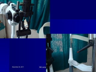
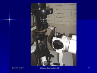

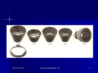

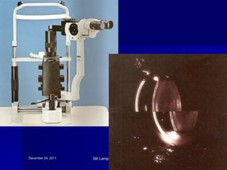


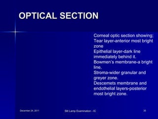


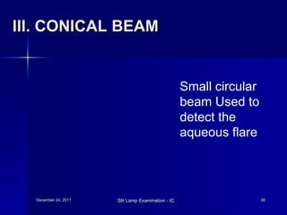


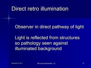
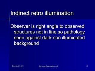


The document discusses slit lamp examination, which allows detailed examination of eye structures using high magnification. It describes the three main components of a slit lamp: the observation system including lenses and eyepiece, illumination system including light source and filters, and mechanical system for adjusting positioning. Various illumination techniques are outlined including diffuse, direct focal, indirect, retro-illumination and specular reflection. Specific uses and methods for examining different eye structures are provided. Specialized uses of slit lamps for procedures like gonioscopy and laser treatment are also mentioned.


