Downloaded 274 times
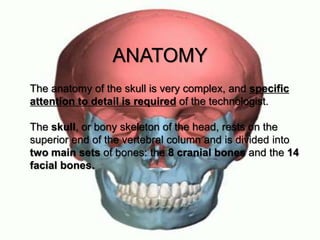
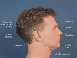
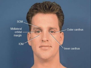
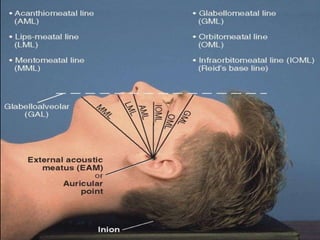
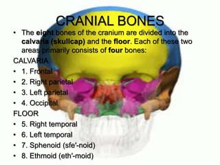
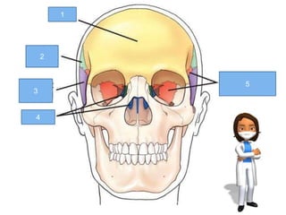
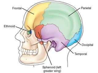
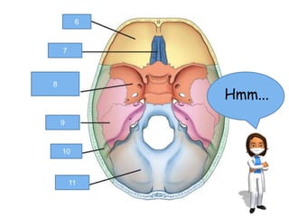
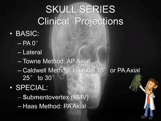
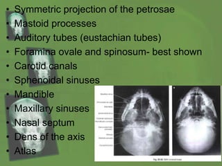
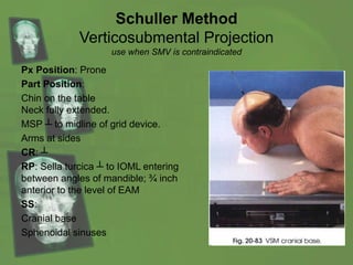
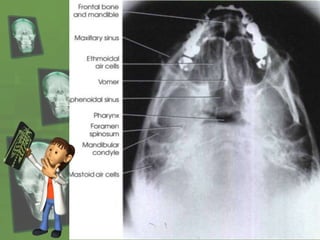

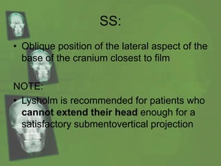


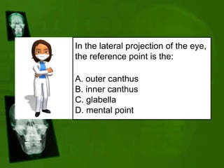
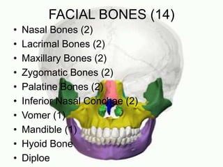

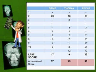


Dr. Matindi introduces skull radiography and engages participants in a competitive game format to enhance learning about skull anatomy and radiographic techniques. The document covers detailed anatomical and positioning information regarding cranial and facial bones, along with various projections used in skull radiography. Participants are encouraged to answer questions related to the information presented to earn points throughout the session.


![Radiography of skull [Autosaved].pptxriuyowioehgg](https://cdn.slidesharecdn.com/ss_thumbnails/radiographyofskullautosaved-251211014507-1d75cfe3-thumbnail.jpg?width=640&height=640&fit=bounds)


![Hypothalamus short notes on location, function and disorders by Dr. Neha [PT]...](https://cdn.slidesharecdn.com/ss_thumbnails/hypothalamusbydr-260124142231-2b48143d-thumbnail.jpg?width=640&height=640&fit=bounds)

