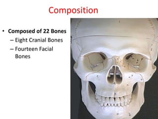
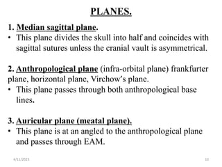
This document discusses skull radiography techniques. It outlines the objectives of skull radiography, the composition and structures of the skull, important lines, planes and landmarks used for positioning. It describes the exposure factors and patient preparation required for different skull views, including the lateral, occipitofrontal and Townes views. Clinical indications for skull radiography and supplementary views like the submentovertex view are also covered.


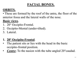


![Radiography of skull [Autosaved].pptxriuyowioehgg](https://cdn.slidesharecdn.com/ss_thumbnails/radiographyofskullautosaved-251211014507-1d75cfe3-thumbnail.jpg?width=640&height=640&fit=bounds)


