Downloaded 181 times


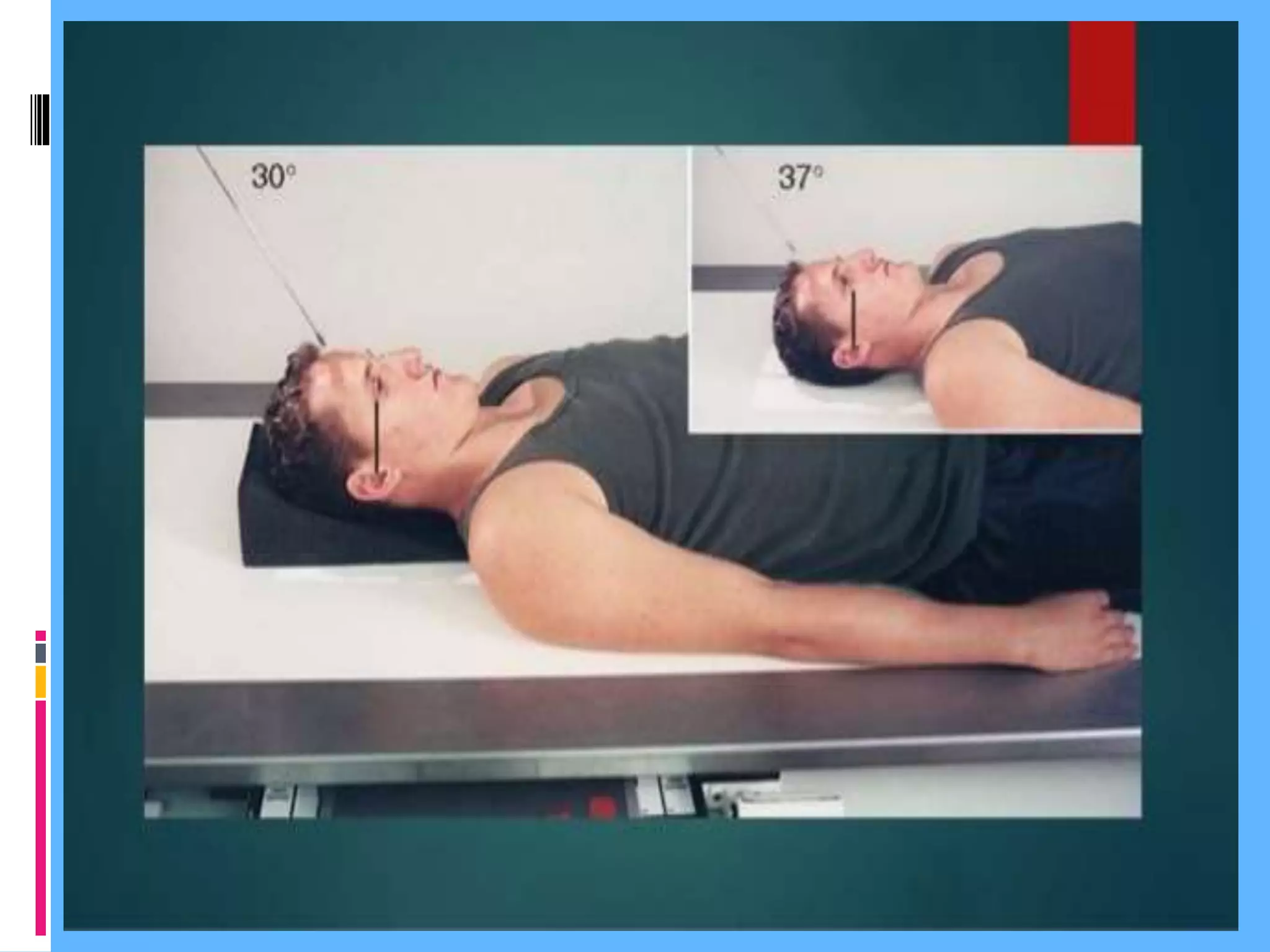


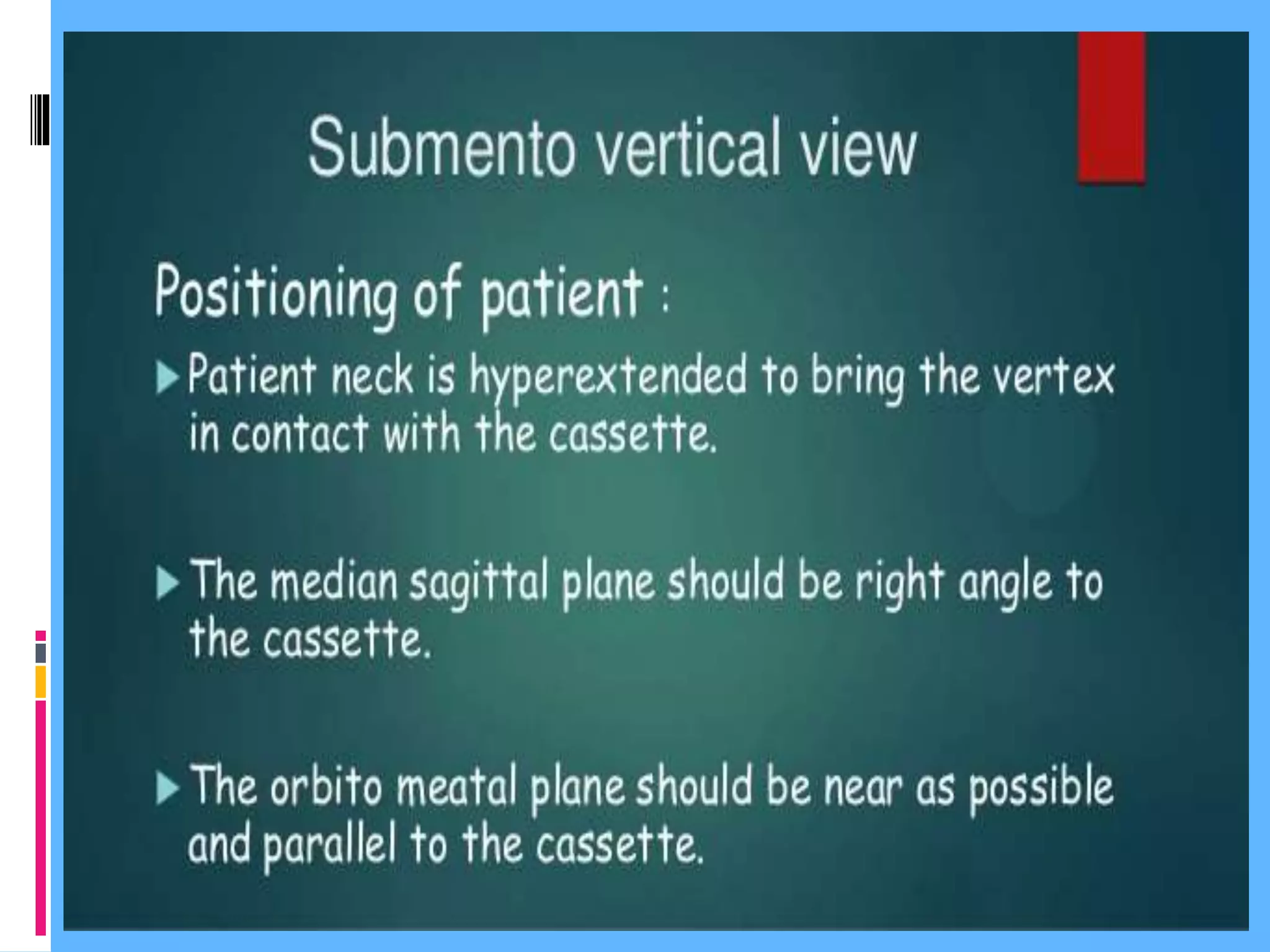


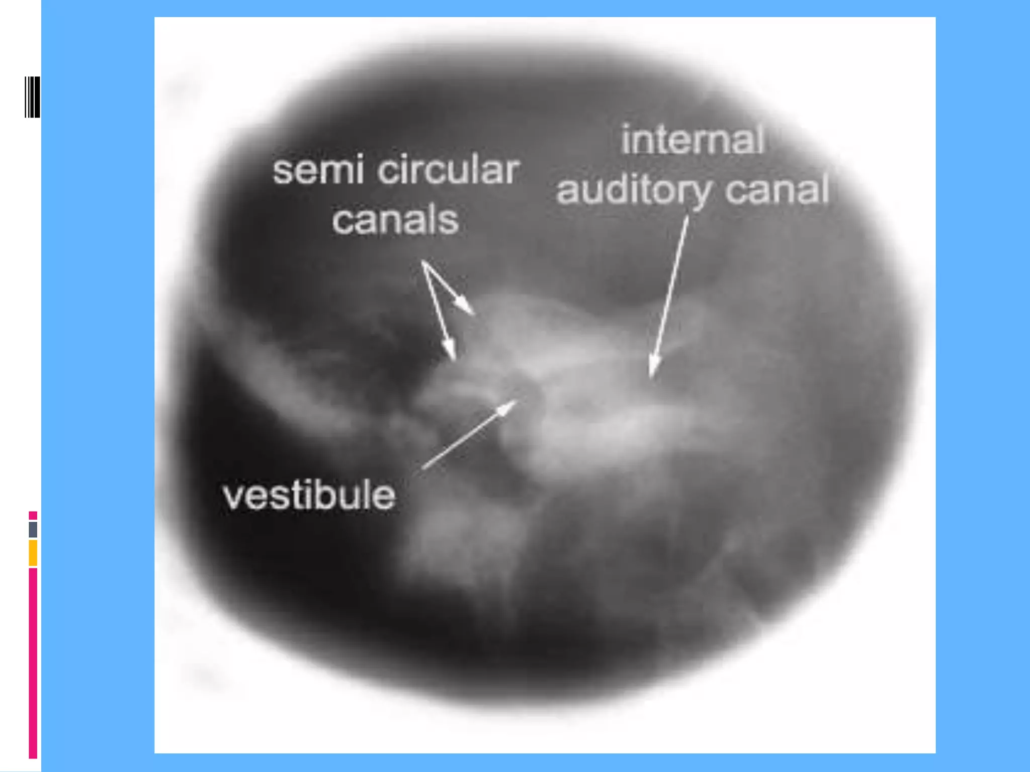


The document discusses various radiographic positioning techniques for imaging different anatomical areas and structures. It provides descriptions of positioning for paranasal sinus views, chest x-rays, spine views, shoulder views including scapula, wrist, hand, elbow, hip, knee and tibia/fibula views. For each area, it specifies the patient positioning, central ray direction, and structures that should be demonstrated in the resulting radiographic image.


