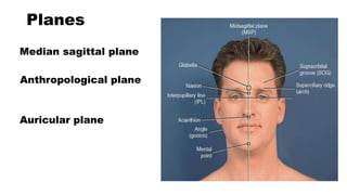
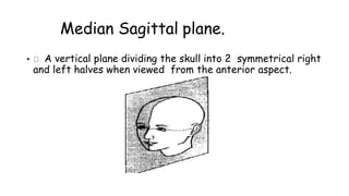
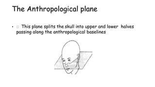
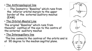
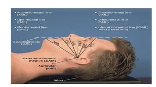
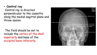
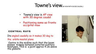
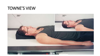
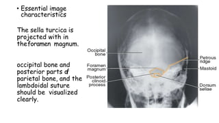
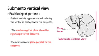
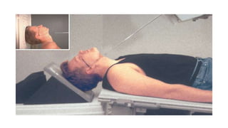
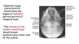
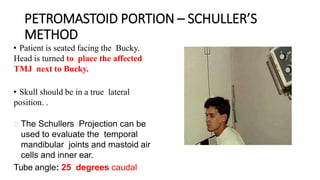
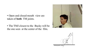
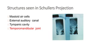
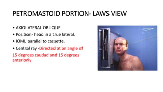
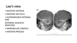
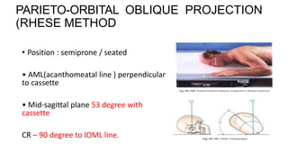
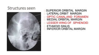
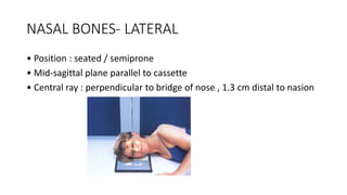
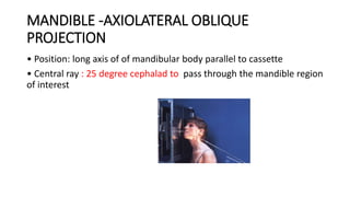
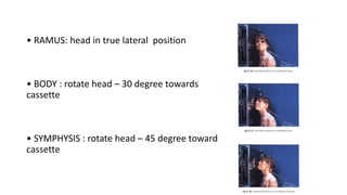
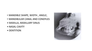
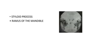
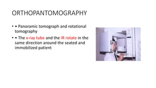
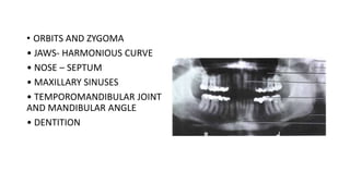
SKELETAL RADIOGRAPHIC
POSITIONING ,NAMED
PROJECTION &NORMAL
VARIANTS - SKULL
BY
DR.KANNAN A.S
FIRST YEAR MDRD
STANLEY RADIOLOGY
SKULL
• The skull is a bony structure that supports the face and forms
a protective cavity for the brain.
• The bones of the skull can be divided into two groups:
cranium
face
• CRANIAL(8)+FACIAL(14)=SKULL BONES(22)
Planes
Median sagittal plane
Anthropological plane
Auricular plane
The Median Sagittal plane.
• A vertical plane dividing the skull into 2 symmetrical right
and left halves when viewed from the anterior aspect.
The Anthropological plane
• This plane splits the skull into upper and lower halves
passing along the anthropological baselines
The Auricular plane
• This plane divides the skull into anterior and posterior
compartments along the Auricular lines
Lines
• Inter orbital line
• Infra orbital line
• Anthropological baseline
• Orbito meatal baseline
• The Anthropological line
• The Isometric “Baseline” which runs from
the inferior orbital margin to the upper
border of the external auditory meatus
(EAM)
• The Orbital-Meatal Line
The original “Baseline” which runs from
theouter canthus of the eye to the centre of
the external auditory meatus
• The Interpupillary line
The line connects the centres of the orbits and is
at 90 degree to the median sagittal plane.
.
POSITIONING CONSIDERATIONS
Projections of the skull may be taken with the patient in the
recumbent or erect position, depending on the patient's
condition.
Images can be obtained in the erect position with the use of a
standard x-ray table in the vertical position or an upright Bucky
Basic views
• Lateral view
• Fronto occipital view ( A P view )
• Fronto occipital with 30 deg caudal ( TOWNE’S
• view)
• Occipito frontal view ( P A view)
• Occipito frontal with 15 deg caudal ( CALDWELL’S
view )
• Submento vertical view(BASILAR view)
• Occipito mental view (WATER’S view)
• parieto-orbital oblique projection (rhese method)
Lateral view
• Position of patient :
Patient sits facing the bucky and the
headis then rotated, such that the
median sagittal plane is parallel to
bucky and inter orbital line is
perpendicular to it.
• C e n t r a l r a y
midway between the glabella and the
extend occipital protuberance to a point
approx 5 cm superior to the external
auditory meatus.
• Essential image characteristics :
The image should contain all cranial bones and
thefirst cervical vertebra.
Fronto occipital view
• Fronto occipital view –skull AP view
• Patient lies supine on a bucky table. Head
is adjusted such that median sagittal
plane at right angles to the film.
• The orbito meatal baseline should be
perpendicular to the cassette
• Central ray
Central ray is directed
perpendicular to the cassette
along the medial sagittal plane and
throw nasion.
The field should be set to
include the vertex of the skull
superiorly and base of the
occipital bone inferiorly.
Towne’s view(AP VIEW WITH 30 DEG CAUDAL )
• Towne’s view is AP view
with 30 degree caudal
• Positioning same as fronto
occipital view
C E N T R A L R AY S
Its angled caudally so it makes 30 deg to
the orbito meatal plane
Centre in the midline such that the beam
passes midway between external auditory
meatuses. This is a point approx 4 cm above
the glabella
TOWNE’S VIEW
• Essential image
characteristics
The sella turcica is
projected with in
theforamen magnum.
occipital bone and
posterior parts of
parietal bone, and the
lambdoidal suture
should be visualized
clearly.
Occipito frontal view
• Positioning of patient :
Patient is seated facing the bucky, so
that the median sagittal plane is with the
midline of the bucky and perpendicular to
it.
Neck is flexed to bring orbito meatal line
perpendicular to the bucky, this can be
achieved by ensuring the nose and
forehead are in contact with the bucky.
• Central ray :
Ray is directed
perpendicular to the bucky
along the median sagittal
plane and at the level of
nasion.
Image should include the
vertex superiorly and base of
occipital bone inferiorly
CALDWELL’S VIEW
• (occipito frontal view with 15 degcaudal )
• Positioning same as occipito frontal view
• Central ray :
• Ray is directed perpendicular to the bucky
done the median sagittal plane.
• The tube is rotated 15 deg caudal to the
orbito meatal baseline
• This view will provide a clear view of
the frontal and ethmoidal sinuses.
• The superior orbital rims can be
evaluated.
Submento vertical view
• Positioning of patient :
• Patient neck is hyperextended to bring
the vertex in contact with the cassette.
• The median sagittal plane should be
right angle to the cassette.
• The orbito meatal plane parallel to the
cassette.
• Central ray :
• Central ray is perpendicular to orbito meatal line.
• Center 1½ inch (4 cm) inferior to the mandibular
symphysis
• Essential image
characteratics :
Should show the
angles of mandible ,
petrous portion of
temporal bone.
The formina of the
middle cranial fossa
should be seen
symmetrically either side
of the midline.
PETROMASTOID PORTION – SCHULLER’S
METHOD
• Patient is seated facing the Bucky.
Head is turned to place the affected
TMJ next to Bucky.
• Skull should be in a true lateral
position. .
The Schullers Projection can be
used to evaluate the temporal
mandibular joints and mastoid air
cells and inner ear.
Tube angle: 25 degrees caudal
• Open and closed mouth view are
taken of both TM joints.
• The TMJ closest to the Bucky will be
the one seen at the center of the film.
Structures seen in Schullers Projection
Mastoid air cells
External auditory canal
Tympanic cavity
Temporomandibular joint
PETROMASTOID PORTION- LAWS VIEW
• AXIOLATERAL OBLIQUE
• Position- head in a true lateral.
• IOML parallel to cassette.
• Central ray -Directed at an angle of
15 degrees caudad and 15 degrees
anteriorly
Law’s view
• MASTOID ANTRUM
• MASTOID AIR CELLS
• SUPERIMPOSED INTERNAL
AND
EXTERNAL ACOUSTIC
MEATUSES
• MANDIBULAR CONDYLE
• MASTOID PROCESS
PARIETO-ORBITAL OBLIQUE PROJECTION
(RHESE METHOD
• Position : semiprone / seated
• AML(acanthomeatal line ) perpendicular
to cassette
• Mid-sagittal plane 53 degree with
cassette
CR – 90 degree to IOML line.
Structures seen SUPERIOR ORBITAL MARGIN
LATERAL ORBIT MARGIN
OPTIC CANALAND FORAMEN
MEDIAL ORBITAL MARGIN
LESSER WING OF SPHENOID
ETHMOID SINUS
INFERIOR ORBITAL MARGIN
NASAL BONES
• LATERAL PROJECTION
• TANGENTIAL PROJECTION
NASAL BONES- LATERAL
• Position : seated / semiprone
• Mid-sagittal plane parallel to cassette
• Central ray : perpendicular to bridge of nose , 1.3 cm distal to nasion
• NASAL BONE
• FRONTONASAL SUTURE
• ANGLE BETWEEN NASAL AND
FRONTAL BONES
• DENSITIES/ LUCENCIES
NASAL BONES-TANGENTIAL
• Position: seated / recumbent
• Inclined cassette
• Central ray: parallel to
glabelloalveolar line
•Septal cartilage
• Nasal bone
PARANASAL SINUSES
• PA AXIAL PROJECTION- CALDWELL
• PARIETOCANTHAL PROJECTION- WATER’S
• PARIETOCANTHAL PROJECTION – WATER’S WITH
OPEN MOUTH
PARANASAL SINUSES
CALDWELL METHOD
• PA axial projection
• CALDWELL METHOD
• Position : extend patient’shead
• IOML forms 15 degree with horizontal
central ray
• Central ray : horizontal – exit at nasion
• FRONTAL SINUS
•ETHMOIDAL SINUS
• PETROUS RIDGE
• SPHENOIDAL SINUS
• MAXILLARY SINUS
Occipito mental view(WATER’S VIEW)
• Positioning of patient :
• The patient is made to sit facing the
cassette.
• Head is adjusted to bring orbito meatal
line to 45 deg to the cassette
• The patient’s nose and chin are
placed in contact with the midline of
cassette.
Central ray
• The ray should is
perpendicularto the median
sagittal plan.
• The ray should be centre to pass
throw the base of nose.
Central ray
Maxillary and ethmoidal sinuses- OPEN
MOUTH WATER’S
• Parietocanthal projection
• OPEN MOUTH WATERS
• Position: OML 37 degree to cassette
• The patient should open the mouth as
wide as possible beforeexposure.
• Central ray: perpendicular- exit acanthion
• • MAXILLARY SINUS
• • SPHENOIDAL SINUSES
ZYGOMATIC ARCH
• SUBMENTOVERTICAL PROJECTION
• TANGENTIAL PROJECTION –MAY METHOD
ZYGOMATIC ARCH-SUBMENTOVERTICAL
PROJECTION
• Position: upright/ supine
• Hyperextend neck-IOML parallel to cassette
• Central ray : perpendicular to IOML
• SHAPE – A LOW ARCH BROADENED AT
BOTH ENDS
• STRUCTURE AND CONTOUR OF THE
ZYGOMATIC ARCH
• SKULL AND FACIAL SKELETON
MAY METHOD
• Tangential projection/ MAY method
• Position: prone/upright
• Neck extended-rest chin on cassette
• Mid-sagittal plane rotated 15 degree
away from side being examined
• Central ray : perpendicular to IOML-
3.8cm posterior to outer canthus
MAY METHOD
• • SHAPE AND STRUCTURE OF ZYGOMATIC ARCH
• • SOFT TISSUES
MANDIBLE -AXIOLATERAL OBLIQUE
PROJECTION
• Position: long axis of of mandibular body parallel to cassette
• Central ray : 25 degree cephalad to pass through the mandible region
of interest
• RAMUS: head in true lateral position
• BODY : rotate head – 30 degree towards
cassette
• SYMPHYSIS : rotate head – 45 degree toward
cassette
• MANDIBLE SHAPE, WIDTH , ANGLE,
• MANDIBULAR CANAL AND CONDYLES
• MAXILLA, MAXILLARY SINUS
• NASAL CAVITY
• DENTITION
Styloid process –CAHOON METHOD
• PA axial
• Rest forehead on cassette
• OML perpendicular to
cassette
• Central ray : nasion – 25
degree cephalad
• STYLOID PROCESS
• RAMUS OF THE MANDIBLE
ORTHOPANTOMOGRAPHY
• • Panoramic tomograph and rotational
tomography
• • The x-ray tube and the IR rotate in the
same direction around the seated and
immobilized patient
• ORBITS AND ZYGOMA
• JAWS- HARMONIOUS CURVE
• NOSE – SEPTUM
• MAXILLARY SINUSES
• TEMPOROMANDIBULAR JOINT
AND MANDIBULAR ANGLE
• DENTITION
Skull positioning by a.s kannan

Skull positioning by a.s kannan

  • 1.
    SKELETAL RADIOGRAPHIC POSITIONING ,NAMED PROJECTION&NORMAL VARIANTS - SKULL BY DR.KANNAN A.S FIRST YEAR MDRD STANLEY RADIOLOGY
  • 2.
    SKULL • The skullis a bony structure that supports the face and forms a protective cavity for the brain. • The bones of the skull can be divided into two groups: cranium face • CRANIAL(8)+FACIAL(14)=SKULL BONES(22)
  • 5.
  • 6.
    The Median Sagittalplane. • A vertical plane dividing the skull into 2 symmetrical right and left halves when viewed from the anterior aspect.
  • 7.
    The Anthropological plane •This plane splits the skull into upper and lower halves passing along the anthropological baselines
  • 8.
    The Auricular plane •This plane divides the skull into anterior and posterior compartments along the Auricular lines
  • 9.
    Lines • Inter orbitalline • Infra orbital line • Anthropological baseline • Orbito meatal baseline
  • 10.
    • The Anthropologicalline • The Isometric “Baseline” which runs from the inferior orbital margin to the upper border of the external auditory meatus (EAM) • The Orbital-Meatal Line The original “Baseline” which runs from theouter canthus of the eye to the centre of the external auditory meatus • The Interpupillary line The line connects the centres of the orbits and is at 90 degree to the median sagittal plane. .
  • 12.
    POSITIONING CONSIDERATIONS Projections ofthe skull may be taken with the patient in the recumbent or erect position, depending on the patient's condition. Images can be obtained in the erect position with the use of a standard x-ray table in the vertical position or an upright Bucky
  • 13.
    Basic views • Lateralview • Fronto occipital view ( A P view ) • Fronto occipital with 30 deg caudal ( TOWNE’S • view) • Occipito frontal view ( P A view) • Occipito frontal with 15 deg caudal ( CALDWELL’S view ) • Submento vertical view(BASILAR view) • Occipito mental view (WATER’S view) • parieto-orbital oblique projection (rhese method)
  • 14.
    Lateral view • Positionof patient : Patient sits facing the bucky and the headis then rotated, such that the median sagittal plane is parallel to bucky and inter orbital line is perpendicular to it.
  • 15.
    • C en t r a l r a y midway between the glabella and the extend occipital protuberance to a point approx 5 cm superior to the external auditory meatus. • Essential image characteristics : The image should contain all cranial bones and thefirst cervical vertebra.
  • 17.
    Fronto occipital view •Fronto occipital view –skull AP view • Patient lies supine on a bucky table. Head is adjusted such that median sagittal plane at right angles to the film. • The orbito meatal baseline should be perpendicular to the cassette
  • 18.
    • Central ray Centralray is directed perpendicular to the cassette along the medial sagittal plane and throw nasion. The field should be set to include the vertex of the skull superiorly and base of the occipital bone inferiorly.
  • 19.
    Towne’s view(AP VIEWWITH 30 DEG CAUDAL ) • Towne’s view is AP view with 30 degree caudal • Positioning same as fronto occipital view C E N T R A L R AY S Its angled caudally so it makes 30 deg to the orbito meatal plane Centre in the midline such that the beam passes midway between external auditory meatuses. This is a point approx 4 cm above the glabella
  • 20.
  • 21.
    • Essential image characteristics Thesella turcica is projected with in theforamen magnum. occipital bone and posterior parts of parietal bone, and the lambdoidal suture should be visualized clearly.
  • 22.
    Occipito frontal view •Positioning of patient : Patient is seated facing the bucky, so that the median sagittal plane is with the midline of the bucky and perpendicular to it. Neck is flexed to bring orbito meatal line perpendicular to the bucky, this can be achieved by ensuring the nose and forehead are in contact with the bucky.
  • 23.
    • Central ray: Ray is directed perpendicular to the bucky along the median sagittal plane and at the level of nasion. Image should include the vertex superiorly and base of occipital bone inferiorly
  • 24.
    CALDWELL’S VIEW • (occipitofrontal view with 15 degcaudal ) • Positioning same as occipito frontal view • Central ray : • Ray is directed perpendicular to the bucky done the median sagittal plane. • The tube is rotated 15 deg caudal to the orbito meatal baseline
  • 26.
    • This viewwill provide a clear view of the frontal and ethmoidal sinuses. • The superior orbital rims can be evaluated.
  • 27.
    Submento vertical view •Positioning of patient : • Patient neck is hyperextended to bring the vertex in contact with the cassette. • The median sagittal plane should be right angle to the cassette. • The orbito meatal plane parallel to the cassette.
  • 29.
    • Central ray: • Central ray is perpendicular to orbito meatal line. • Center 1½ inch (4 cm) inferior to the mandibular symphysis
  • 30.
    • Essential image characteratics: Should show the angles of mandible , petrous portion of temporal bone. The formina of the middle cranial fossa should be seen symmetrically either side of the midline.
  • 31.
    PETROMASTOID PORTION –SCHULLER’S METHOD • Patient is seated facing the Bucky. Head is turned to place the affected TMJ next to Bucky. • Skull should be in a true lateral position. . The Schullers Projection can be used to evaluate the temporal mandibular joints and mastoid air cells and inner ear. Tube angle: 25 degrees caudal
  • 32.
    • Open andclosed mouth view are taken of both TM joints. • The TMJ closest to the Bucky will be the one seen at the center of the film.
  • 33.
    Structures seen inSchullers Projection Mastoid air cells External auditory canal Tympanic cavity Temporomandibular joint
  • 34.
    PETROMASTOID PORTION- LAWSVIEW • AXIOLATERAL OBLIQUE • Position- head in a true lateral. • IOML parallel to cassette. • Central ray -Directed at an angle of 15 degrees caudad and 15 degrees anteriorly
  • 35.
    Law’s view • MASTOIDANTRUM • MASTOID AIR CELLS • SUPERIMPOSED INTERNAL AND EXTERNAL ACOUSTIC MEATUSES • MANDIBULAR CONDYLE • MASTOID PROCESS
  • 36.
    PARIETO-ORBITAL OBLIQUE PROJECTION (RHESEMETHOD • Position : semiprone / seated • AML(acanthomeatal line ) perpendicular to cassette • Mid-sagittal plane 53 degree with cassette CR – 90 degree to IOML line.
  • 37.
    Structures seen SUPERIORORBITAL MARGIN LATERAL ORBIT MARGIN OPTIC CANALAND FORAMEN MEDIAL ORBITAL MARGIN LESSER WING OF SPHENOID ETHMOID SINUS INFERIOR ORBITAL MARGIN
  • 38.
    NASAL BONES • LATERALPROJECTION • TANGENTIAL PROJECTION
  • 39.
    NASAL BONES- LATERAL •Position : seated / semiprone • Mid-sagittal plane parallel to cassette • Central ray : perpendicular to bridge of nose , 1.3 cm distal to nasion
  • 40.
    • NASAL BONE •FRONTONASAL SUTURE • ANGLE BETWEEN NASAL AND FRONTAL BONES • DENSITIES/ LUCENCIES
  • 41.
    NASAL BONES-TANGENTIAL • Position:seated / recumbent • Inclined cassette • Central ray: parallel to glabelloalveolar line
  • 42.
  • 43.
    PARANASAL SINUSES • PAAXIAL PROJECTION- CALDWELL • PARIETOCANTHAL PROJECTION- WATER’S • PARIETOCANTHAL PROJECTION – WATER’S WITH OPEN MOUTH
  • 44.
  • 45.
    CALDWELL METHOD • PAaxial projection • CALDWELL METHOD • Position : extend patient’shead • IOML forms 15 degree with horizontal central ray • Central ray : horizontal – exit at nasion
  • 46.
    • FRONTAL SINUS •ETHMOIDALSINUS • PETROUS RIDGE • SPHENOIDAL SINUS • MAXILLARY SINUS
  • 47.
    Occipito mental view(WATER’SVIEW) • Positioning of patient : • The patient is made to sit facing the cassette. • Head is adjusted to bring orbito meatal line to 45 deg to the cassette • The patient’s nose and chin are placed in contact with the midline of cassette.
  • 49.
    Central ray • Theray should is perpendicularto the median sagittal plan. • The ray should be centre to pass throw the base of nose. Central ray
  • 50.
    Maxillary and ethmoidalsinuses- OPEN MOUTH WATER’S • Parietocanthal projection • OPEN MOUTH WATERS • Position: OML 37 degree to cassette • The patient should open the mouth as wide as possible beforeexposure. • Central ray: perpendicular- exit acanthion
  • 51.
    • • MAXILLARYSINUS • • SPHENOIDAL SINUSES
  • 52.
    ZYGOMATIC ARCH • SUBMENTOVERTICALPROJECTION • TANGENTIAL PROJECTION –MAY METHOD
  • 53.
    ZYGOMATIC ARCH-SUBMENTOVERTICAL PROJECTION • Position:upright/ supine • Hyperextend neck-IOML parallel to cassette • Central ray : perpendicular to IOML
  • 54.
    • SHAPE –A LOW ARCH BROADENED AT BOTH ENDS • STRUCTURE AND CONTOUR OF THE ZYGOMATIC ARCH • SKULL AND FACIAL SKELETON
  • 55.
    MAY METHOD • Tangentialprojection/ MAY method • Position: prone/upright • Neck extended-rest chin on cassette • Mid-sagittal plane rotated 15 degree away from side being examined • Central ray : perpendicular to IOML- 3.8cm posterior to outer canthus
  • 56.
    MAY METHOD • •SHAPE AND STRUCTURE OF ZYGOMATIC ARCH • • SOFT TISSUES
  • 57.
    MANDIBLE -AXIOLATERAL OBLIQUE PROJECTION •Position: long axis of of mandibular body parallel to cassette • Central ray : 25 degree cephalad to pass through the mandible region of interest
  • 58.
    • RAMUS: headin true lateral position • BODY : rotate head – 30 degree towards cassette • SYMPHYSIS : rotate head – 45 degree toward cassette
  • 59.
    • MANDIBLE SHAPE,WIDTH , ANGLE, • MANDIBULAR CANAL AND CONDYLES • MAXILLA, MAXILLARY SINUS • NASAL CAVITY • DENTITION
  • 60.
    Styloid process –CAHOONMETHOD • PA axial • Rest forehead on cassette • OML perpendicular to cassette • Central ray : nasion – 25 degree cephalad
  • 61.
    • STYLOID PROCESS •RAMUS OF THE MANDIBLE
  • 62.
    ORTHOPANTOMOGRAPHY • • Panoramictomograph and rotational tomography • • The x-ray tube and the IR rotate in the same direction around the seated and immobilized patient
  • 63.
    • ORBITS ANDZYGOMA • JAWS- HARMONIOUS CURVE • NOSE – SEPTUM • MAXILLARY SINUSES • TEMPOROMANDIBULAR JOINT AND MANDIBULAR ANGLE • DENTITION