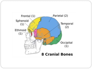
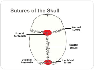
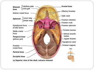
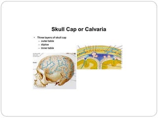
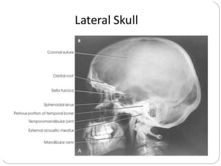
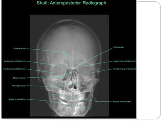
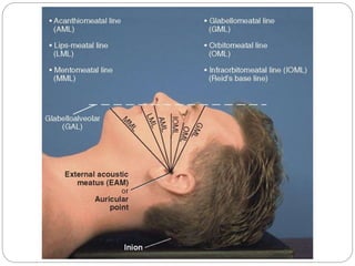
DR. AMIT RAUNIYAR
RESIDENT( 1ST YEAR)
RADIODIAGNOSIS & IMAGING
NAMS
SKULL ANATOMY
AND
RADIOLOGICAL POSITIONING
SKULL
 The skull is a bony structure that supports the
face and forms a protective cavity for the brain.
 It is comprised of many bones, formed by
intramembranous ossification, which are joined
together by sutures (fibrous joints).
 The bones of the skull can be divided into two
groups: those of the cranium (which can be
subdivided the skullcap/calvarium, and the
cranial base) and those of the face.
CRANIAL(8)+FACIAL(14)=SKUL
L BONES(22)
Sutures of the Skull
FONTANELLE
FOSSAE OF BRAIN
PARANASAL SINUSES
SKULL TOPOGRAPHY
Landmarks
 Outer canthus of the eye:
 the point where the upper and lower eyelids meet laterally.
 Infra-orbital margin/point:
 the inferior rim of the orbit, with the point being located at its lowest
point.
 Nasion:
 the articulation between the nasal and frontal bones.
 Glabella:
 a bony prominence found on the frontal bone immediately superior to the
nasion.
 Vertex:
 the highest point of the skull in the median sagittal plane.
 External occipital protuberance (inion):
 a bony prominence found on the occipital bone, usually coincident with
the median sagittal plane.
 External auditory meatus:
 the opening within the ear that leads into the external auditory canal.
Lines
 Inter-orbital (inter-pupillary) line:
 joins the centre of the two orbits or the centre of the two
pupils when the eyes are looking straight forward.
 Infra-orbital line:
 joints the two infra-orbital points.
 Anthropological baseline:
 passes from the infra-orbital point to the upper border of
the external auditory meatus (also known as the
Frankfurter line).
 Orbito-meatal base line (radiographic baseline):
 Extends from the outer canthus of the eye to the centre
of the external auditory meatus. This line is angled
approximately 10 degrees to the anthropological
baseline.
Planes
 Median sagittal plane:
 divides the skull into right and left halves. Landmarks on this
plane are the nasion anteriorly and the external occipital
protuberance (inion) posteriorly.
 Coronal planes
 these are at right-angles to the median sagittal plane and
divide the head into anterior and posterior parts.
 Anthropological plane:
 a horizontal plane containing the two anthropological
baselines and the infra-orbital line. It is an example of an axial
plane. Axial planes are parallel with this plane.
 Auricular plane:
 perpendicular to the anthropological plane. Passes through
the centre of the two external auditory meatuses. It is an
example of a coronal plane.
 The median sagittal, anthropological and coronal planes
are mutually at right-angles.
POSITIONING
CONSIDERATIONS
 Projections of the skull may be taken with the
patient in the recumbent or erect position,
depending on the patient's condition.
 Images can be obtained in the erect position with
the use of a standard x-ray table in the vertical
position or an upright Bucky.
PATIENT PREPARATION
 Ensure that all metal objects are removed from
the patient, e.g. hair clips and hairpins.
 Bunches of hair often produce artefacts and thus
should be untied.
 False teeth containing metal and metal dental
bridges should be removed.
USEFUL ACCESSORIES
 Every effort should be made to make the patient's
body as comfortable as possible,
 Positioning aids such as sponges, sandbags,
and pillows should be used if needed.
 Except in cases of severe trauma, respiration
should be suspended during the exposure to help
prevent blurring of the image caused by breathing
movements of the thorax.
Source to image receptor
distance(SID)
The minimum SID with the image receptor in the
table or upright Bucky is 40 inches (100 cm).
Radiation Protection
The best techniques for minimizing radiation
exposure to the patient in skull radiography are to
(1) use good collimation practices,
(2) immobilize the head when necessary,
minimizing repeats, and
(3) center properly.
Gonadal shielding
 Generally, with accurate collimation, no
detectable contribution to gonadal exposure
occurs during radiography of the skull. However,
lead shields should be used to reassure the
patient.
BASIC VIEWS
 LATERAL
 OCCIPITO FRONTAL / PA 0°
 PA- AXIAL 15° (CALDWELL) or PA axial 25° to
30°
 FRONTO OCCCIPITAL / AP VIEW
 AP-AXIAL (TOWNE)
PA 0°
 The skull PA view is
a non-angled PA
radiograph of the
skull. This view
provides an overview
of the entire skull
rather than attempting
to highlight any one
region.
PA 0°
Part Position
 Flex neck, aligning OML
perpendicular to IR.
 Align midsagittal plane
perpendicular to midline of
table/Bucky to prevent head
rotation and/or tilt (EAMs
same distance from
table/Bucky surface).
 centring point
 the beam is exiting at the
nasion
 Rest patient's nose and
forehead against table/Bucky
surface.
 Center IR(Image receptor) to
CR(central ray).
 Structures Shown:
Frontal bone, crista
galli, internal auditory
canals, frontal and
anterior ethmoid
sinuses, petrous
ridges, greater and
lesser wings of
sphenoid.
 Pathology
demonstrated: Skull
fractures (medial and
lateral displacement)
PA AXIAL PROJECTION
(Caldwell Method)
 The Caldwell view is a caudally angled PA 15°
CR or 25° to 30° CR radiograph of the skull,
designed to better visualise the paranasal
sinuses, especially the frontal sinus.
 Alternate 25° to 30°: An alternate projecion that
allows better visualization of the superior orbital
fissures , the foramen rotundum, and the inferior
orbital rim
PA AXIAL PROJECTION
(Caldwell Method)
 OML perpendicular to
IR.
 Angle CR 15° caudad
and
 Alternate with CR 25°
to 30° caudad,
 OML forms 15 degree
with horizontal central
ray
 center to exit at
nasion
 Part Position
 Rest patient's nose and
forehead against
table/Bucky surface.
 Flex neck as needed to
align OML
perpendicular to IR.
 Align midsagittal plane
perpendicular to midline
of the grid or
table/Bucky surface to
prevent head rotation
and/or tilt.
 Structures Shown:
Greater and lesser
sphenoid wings,
 frontal bone, superior
orbital fissures, frontal
and anterior ethmoid
sinuses, superior
orbital margins, and
crista galli are shown.
AP view
 The skull AP view is a
nonangled AP radiograph
of the skull. This view
provides an overview of
the entire skull rather than
attempting to highlight any
one region.
 Position : supine
 OML perpendicular to
Cassette(IR)
 the beam travels anterior
to posterior (AP) direction,
with 0° of angulation
through the nasion.
 Central ray :perpendicular
5cm above nasion
AP AXIAL(TOWNE)
 The Towne view is an
angled AP radiograph
of the skull.
 AP AXIAL projection
 Position :
prone/seated
 OML perpendicular to
cassette(IR).
 For patients unable
to flex their neck to
this extent, align the
IOML perpendicular to
the IR.
 Central Ray
 Angle CR 30° caudad to
OML, or 37° caudad to
IOML. (A 7° difference
exists between the OML
and the IOML.)
 Center at the
midsagittal plane 2.
inches (6.5 cm) above
the glabella to pass
through the foramen
magnum at the level of
the base of the occiput.
 Center IR to projected
CR.
Advantages
 Occipital bone and posterior fossa space better
evaluated than with a nonangulated AP view,
which would have more skull base and facial
bone overlap
 May be a useful additional view for evaluating
skull fractures
 Structures seen:
 Occipital bone,
petrous pyramids, and
foramen magnum are
shown with the
dorsum sellae and
posterior clinoids
visualized in the
shadow of the
foramen magnum.
Lateral view
 It is named according to
the side of the head
nearer to the image
receptor.
 Central Ray
 Align CR perpendicular to
IR.
 Center to a point 2.5
inches (5 cm) superior to
EAM .
 IOML is perpendicular to
cassette
 Pathology Demonstrated
 Skull fractures. A common
general skull routine
includes both right and left
 Part Position
 Place the head in a
true lateral position, with
the side of interest
closest to IR and the
patient's body in a
semiprone position as
needed for comfort.
 Align midsagittal plane
parallel to IR, ensuring
no rotation or tilt.
 Align interpupillary line
perpendicular to IR,
ensuring no tilt of head .
 Structures seen:
 Superimposed cranial
halves with superior
detail of the lateral
cranium closest to the
IR are demonstrated.
 The entire sella turcica,
including anterior and
posterior clinoids and
dorsum sellae, is also
shown.
 The sella turcica and
clivus are demonstrated
in profile.
OTHER VIEWS
Schullers Projection
 The Schullers
Projection can be
used to evaluate the
temporal mandibular
joints and mastoid air
cells and inner ear.
 Tube angle: 25
degrees caudal
Structures seen
 Mastoid air cells
 External auditory
canal
 Tympanic cavity
 Temporomandibular
joint
ORBIT
 • PARIETO-ORBITAL
OBLIQUE
PROJECTION
(RHESE METHOD)
 SUPERIOR ORBITAL
MARGIN
 • LATERAL ORBIT
MARGIN
 • OPTIC CANAL AND
FORAMEN
 • MEDIAL ORBITAL
MARGIN
 • LESSER WING OF
SPHENOID
 • ETHMOID SINUS
 • INFERIOR ORBITAL
MARGIN
FACIAL BONES
• LATERAL PROJECTION • PARIETO-ACANTHAL PROJECTION
(WATER’S)
NASAL BONES
 LATERAL
PROJECTION
 • TANGENTIAL
PROJECTION
• NASAL BONE
Septal cartilage
• Nasal bone
PARANASAL SINUSES
 PA AXIAL PROJECTION- CALDWELL
 PARIETOCANTHAL PROJECTION- WATER’S
for maxillary sinuses
 • PARIETOCANTHAL PROJECTION – WATER’S
WITH OPEN MOUTH
 For maxillary and ethmoidal sinuses
Sinus lateral
 Sinus Lateral
 The lateral view of the
sinuses and facial
bones
will under exposed for
the
skull.
 This view is very
useful
for seeing fluid levels
in
all of the sinuses.
ZYGOMATIC ARCH
 SUBMENTOVERTICAL PROJECTION
 TANGENTIAL PROJECTION –MAY METHOD
BIBLIOGRAPHY
 Textbook of Radiology and Imaging( 7th edition)
by David Sutton
 Clarke’s Positioning in Radiography ( 12th edition)
 Radiopaedia
THANK YOU
Skull anatomy and positioning

Skull anatomy and positioning

  • 1.
    DR. AMIT RAUNIYAR RESIDENT(1ST YEAR) RADIODIAGNOSIS & IMAGING NAMS SKULL ANATOMY AND RADIOLOGICAL POSITIONING
  • 2.
    SKULL  The skullis a bony structure that supports the face and forms a protective cavity for the brain.  It is comprised of many bones, formed by intramembranous ossification, which are joined together by sutures (fibrous joints).  The bones of the skull can be divided into two groups: those of the cranium (which can be subdivided the skullcap/calvarium, and the cranial base) and those of the face.
  • 5.
  • 6.
  • 9.
  • 10.
  • 15.
  • 16.
  • 17.
    Landmarks  Outer canthusof the eye:  the point where the upper and lower eyelids meet laterally.  Infra-orbital margin/point:  the inferior rim of the orbit, with the point being located at its lowest point.  Nasion:  the articulation between the nasal and frontal bones.  Glabella:  a bony prominence found on the frontal bone immediately superior to the nasion.  Vertex:  the highest point of the skull in the median sagittal plane.  External occipital protuberance (inion):  a bony prominence found on the occipital bone, usually coincident with the median sagittal plane.  External auditory meatus:  the opening within the ear that leads into the external auditory canal.
  • 20.
    Lines  Inter-orbital (inter-pupillary)line:  joins the centre of the two orbits or the centre of the two pupils when the eyes are looking straight forward.  Infra-orbital line:  joints the two infra-orbital points.  Anthropological baseline:  passes from the infra-orbital point to the upper border of the external auditory meatus (also known as the Frankfurter line).  Orbito-meatal base line (radiographic baseline):  Extends from the outer canthus of the eye to the centre of the external auditory meatus. This line is angled approximately 10 degrees to the anthropological baseline.
  • 22.
    Planes  Median sagittalplane:  divides the skull into right and left halves. Landmarks on this plane are the nasion anteriorly and the external occipital protuberance (inion) posteriorly.  Coronal planes  these are at right-angles to the median sagittal plane and divide the head into anterior and posterior parts.  Anthropological plane:  a horizontal plane containing the two anthropological baselines and the infra-orbital line. It is an example of an axial plane. Axial planes are parallel with this plane.  Auricular plane:  perpendicular to the anthropological plane. Passes through the centre of the two external auditory meatuses. It is an example of a coronal plane.  The median sagittal, anthropological and coronal planes are mutually at right-angles.
  • 23.
    POSITIONING CONSIDERATIONS  Projections ofthe skull may be taken with the patient in the recumbent or erect position, depending on the patient's condition.  Images can be obtained in the erect position with the use of a standard x-ray table in the vertical position or an upright Bucky.
  • 24.
    PATIENT PREPARATION  Ensurethat all metal objects are removed from the patient, e.g. hair clips and hairpins.  Bunches of hair often produce artefacts and thus should be untied.  False teeth containing metal and metal dental bridges should be removed.
  • 25.
  • 26.
     Every effortshould be made to make the patient's body as comfortable as possible,  Positioning aids such as sponges, sandbags, and pillows should be used if needed.  Except in cases of severe trauma, respiration should be suspended during the exposure to help prevent blurring of the image caused by breathing movements of the thorax.
  • 27.
    Source to imagereceptor distance(SID) The minimum SID with the image receptor in the table or upright Bucky is 40 inches (100 cm).
  • 28.
    Radiation Protection The besttechniques for minimizing radiation exposure to the patient in skull radiography are to (1) use good collimation practices, (2) immobilize the head when necessary, minimizing repeats, and (3) center properly.
  • 29.
    Gonadal shielding  Generally,with accurate collimation, no detectable contribution to gonadal exposure occurs during radiography of the skull. However, lead shields should be used to reassure the patient.
  • 30.
    BASIC VIEWS  LATERAL OCCIPITO FRONTAL / PA 0°  PA- AXIAL 15° (CALDWELL) or PA axial 25° to 30°  FRONTO OCCCIPITAL / AP VIEW  AP-AXIAL (TOWNE)
  • 31.
    PA 0°  Theskull PA view is a non-angled PA radiograph of the skull. This view provides an overview of the entire skull rather than attempting to highlight any one region.
  • 32.
    PA 0° Part Position Flex neck, aligning OML perpendicular to IR.  Align midsagittal plane perpendicular to midline of table/Bucky to prevent head rotation and/or tilt (EAMs same distance from table/Bucky surface).  centring point  the beam is exiting at the nasion  Rest patient's nose and forehead against table/Bucky surface.  Center IR(Image receptor) to CR(central ray).
  • 33.
     Structures Shown: Frontalbone, crista galli, internal auditory canals, frontal and anterior ethmoid sinuses, petrous ridges, greater and lesser wings of sphenoid.  Pathology demonstrated: Skull fractures (medial and lateral displacement)
  • 34.
    PA AXIAL PROJECTION (CaldwellMethod)  The Caldwell view is a caudally angled PA 15° CR or 25° to 30° CR radiograph of the skull, designed to better visualise the paranasal sinuses, especially the frontal sinus.  Alternate 25° to 30°: An alternate projecion that allows better visualization of the superior orbital fissures , the foramen rotundum, and the inferior orbital rim
  • 35.
    PA AXIAL PROJECTION (CaldwellMethod)  OML perpendicular to IR.  Angle CR 15° caudad and  Alternate with CR 25° to 30° caudad,  OML forms 15 degree with horizontal central ray  center to exit at nasion
  • 36.
     Part Position Rest patient's nose and forehead against table/Bucky surface.  Flex neck as needed to align OML perpendicular to IR.  Align midsagittal plane perpendicular to midline of the grid or table/Bucky surface to prevent head rotation and/or tilt.
  • 37.
     Structures Shown: Greaterand lesser sphenoid wings,  frontal bone, superior orbital fissures, frontal and anterior ethmoid sinuses, superior orbital margins, and crista galli are shown.
  • 38.
    AP view  Theskull AP view is a nonangled AP radiograph of the skull. This view provides an overview of the entire skull rather than attempting to highlight any one region.  Position : supine  OML perpendicular to Cassette(IR)  the beam travels anterior to posterior (AP) direction, with 0° of angulation through the nasion.  Central ray :perpendicular 5cm above nasion
  • 39.
    AP AXIAL(TOWNE)  TheTowne view is an angled AP radiograph of the skull.  AP AXIAL projection  Position : prone/seated  OML perpendicular to cassette(IR).  For patients unable to flex their neck to this extent, align the IOML perpendicular to the IR.
  • 40.
     Central Ray Angle CR 30° caudad to OML, or 37° caudad to IOML. (A 7° difference exists between the OML and the IOML.)  Center at the midsagittal plane 2. inches (6.5 cm) above the glabella to pass through the foramen magnum at the level of the base of the occiput.  Center IR to projected CR.
  • 41.
    Advantages  Occipital boneand posterior fossa space better evaluated than with a nonangulated AP view, which would have more skull base and facial bone overlap  May be a useful additional view for evaluating skull fractures
  • 42.
     Structures seen: Occipital bone, petrous pyramids, and foramen magnum are shown with the dorsum sellae and posterior clinoids visualized in the shadow of the foramen magnum.
  • 43.
    Lateral view  Itis named according to the side of the head nearer to the image receptor.  Central Ray  Align CR perpendicular to IR.  Center to a point 2.5 inches (5 cm) superior to EAM .  IOML is perpendicular to cassette  Pathology Demonstrated  Skull fractures. A common general skull routine includes both right and left
  • 44.
     Part Position Place the head in a true lateral position, with the side of interest closest to IR and the patient's body in a semiprone position as needed for comfort.  Align midsagittal plane parallel to IR, ensuring no rotation or tilt.  Align interpupillary line perpendicular to IR, ensuring no tilt of head .
  • 45.
     Structures seen: Superimposed cranial halves with superior detail of the lateral cranium closest to the IR are demonstrated.  The entire sella turcica, including anterior and posterior clinoids and dorsum sellae, is also shown.  The sella turcica and clivus are demonstrated in profile.
  • 46.
  • 47.
    Schullers Projection  TheSchullers Projection can be used to evaluate the temporal mandibular joints and mastoid air cells and inner ear.  Tube angle: 25 degrees caudal
  • 49.
    Structures seen  Mastoidair cells  External auditory canal  Tympanic cavity  Temporomandibular joint
  • 50.
  • 51.
     SUPERIOR ORBITAL MARGIN • LATERAL ORBIT MARGIN  • OPTIC CANAL AND FORAMEN  • MEDIAL ORBITAL MARGIN  • LESSER WING OF SPHENOID  • ETHMOID SINUS  • INFERIOR ORBITAL MARGIN
  • 52.
    FACIAL BONES • LATERALPROJECTION • PARIETO-ACANTHAL PROJECTION (WATER’S)
  • 53.
    NASAL BONES  LATERAL PROJECTION • TANGENTIAL PROJECTION
  • 54.
    • NASAL BONE Septalcartilage • Nasal bone
  • 55.
    PARANASAL SINUSES  PAAXIAL PROJECTION- CALDWELL  PARIETOCANTHAL PROJECTION- WATER’S for maxillary sinuses  • PARIETOCANTHAL PROJECTION – WATER’S WITH OPEN MOUTH  For maxillary and ethmoidal sinuses
  • 57.
    Sinus lateral  SinusLateral  The lateral view of the sinuses and facial bones will under exposed for the skull.  This view is very useful for seeing fluid levels in all of the sinuses.
  • 58.
    ZYGOMATIC ARCH  SUBMENTOVERTICALPROJECTION  TANGENTIAL PROJECTION –MAY METHOD
  • 59.
    BIBLIOGRAPHY  Textbook ofRadiology and Imaging( 7th edition) by David Sutton  Clarke’s Positioning in Radiography ( 12th edition)  Radiopaedia
  • 60.