Downloaded 625 times


![43
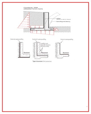
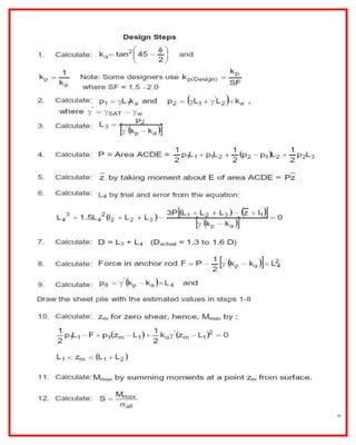
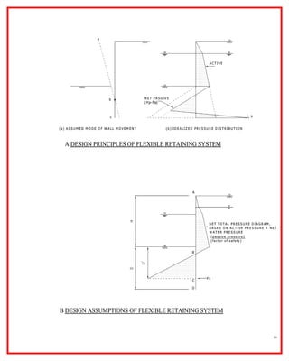
embedded depth can be determined by summarizing horizontal earth pressures and moments about
the anchor.
Fx = 0 [1]
Mo = 0 [2]
the lateral earth pressure is a function of embedded depth. Both equations are highly nonlinear. A
trial and error method has to be used to determine the root.
r structural design, the sheet pile needs to be able to withstand maximum moment and shear from
lateral pressure. A structural analysis needs to be done to determine maximum moment and
shear.](https://image.slidesharecdn.com/retainingwall-150806080725-lva1-app6892/85/Retaining-wall-Scant-Piles-43-320.jpg)


![48
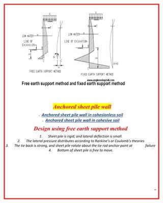
Example 3. Design anchored sheet pile in cohesionless soil.
Depth of excavation, h = 10 ft
Unit weight of soil, = 115 lb/ft3
Internal friction angle, = 30 degree
Allowable design stress of sheet pile = 32 ksi
Yield strength of soldier beam, Fy = 36 ksi
Location of tie rod at 2 ft below ground surface, spacing, s = 12 ft
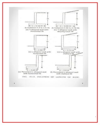
Requirement: Design length of an anchored sheet pile, select sheet pile section, and design tie rod
Solution:
Design length of sheet pile:
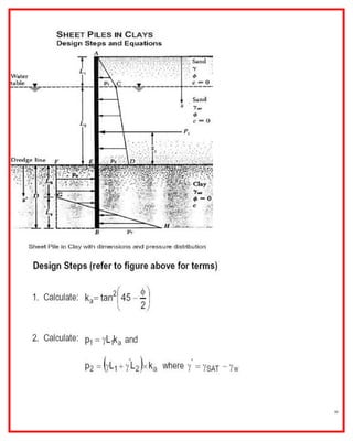
Calculate lateral earth pressure coefficients:
Ka = tan (45-/2) = 0.333
Kp = tan (45-/2) = 3
The lateral earth pressure at bottom of excavation is
pa = Ka h = 0.333*115*10 = 383.33 psf
The active lateral force above excavation
Ha1 = pa*h/2 = 383.33*10/2 = 1917 lb/ft
The depth a = pa / (Kp-Ka) = 383.3 / [115*(3-0.333)] =1.25 ft
The corresponding lateral force
Ha2 = pa*a/2 = 383.33*1.25/2 = 238.6 lb/ft
Assume Y = 2.85 ft
HCEF = (Kp-Ka) Y2
/3 = 115*(3-0.333)*2.852
/3 = 830.3 lb/ft
y1 = (2h/3-b) = (2*10/3-2)=4.67 ft
y2 = (h+a/3-b) = (10+1.25/3-2)=8.42 ft
y3 = (h+a+2Y/3) = (10+1.25+2*2.85/3) = 13.15 ft](https://image.slidesharecdn.com/retainingwall-150806080725-lva1-app6892/85/Retaining-wall-Scant-Piles-48-320.jpg)


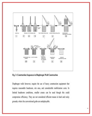


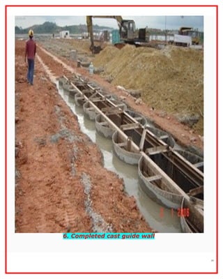


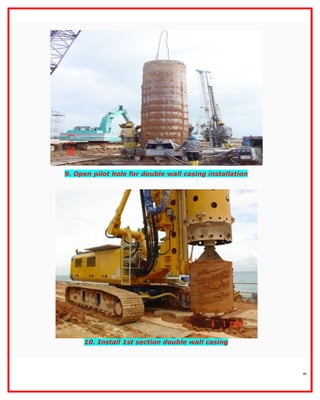


The document outlines the construction and design principles of steel sheet piling, emphasizing its lightweight, reusable, and durable characteristics. It describes the installation process, various anchoring methods, and how to calculate the lateral and passive earth pressures relevant to the design. Additionally, it provides examples of structural analysis necessary for determining the sizes and strengths of sheet piles and associated components like tie rods and soldier beams.