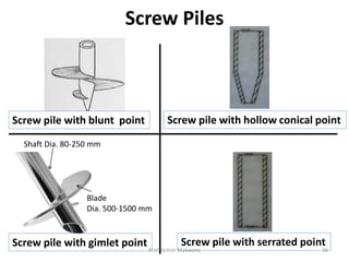
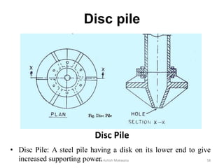
SlideShare a Scribd company logo
Prepared By
Prof. Ashish Makwana
Civil Engg. Dept.
Prof. Ashish Makwana 1
PRESENTATION
OUTLINE…
• Introduction
• Uses of Piles
• Factors affecting selection of type of piles
• Types of Piles
• Pile Spacing
• Group of Piles
• Efficiency of Group of Piles
• Pile Cap and Pile shoe
Prof. Ashish Makwana 2
PRESENTATION
OUTLINE…
• Load tests on piles
• Pile driving
• Pulling of piles
• Loads on piles
• Causes of failure of piles
• Pile driving formulas
Prof. Ashish Makwana 3
INTRODUCTION
• When the depth of foundation is more than the
width of foundation then it is termed as deep
foundations.
• The deep foundations are classified as below :
– Pile foundations
– Cofferdams
– Caissons
Prof. Ashish Makwana 4
Pile foundation
CaissonCofferdam Prof. Ashish Makwana 5
Pile foundation
Prof. Ashish Makwana 6
PILE FOUNDATION
• Pile foundation is that type of deep foundation in
which the loads are taken to a low level by means of
vertical members which may be of timber, concrete
or steel.
Prof. Ashish Makwana 7
Pile applications
Soft to
Firm Clay
Large Distributed
Weight
Very Large Concentrated
Weight
Strong Rock
Low
Weight
Prof. Ashish Makwana 8
USES OF PILES
• (i) Pile foundation is generally used, when simple
spread foundation at a suitable depth is not possible
either because the stratum of required bearing
capacity is at a greater depth or steep slopes are
encountered.
• (ii) In compressible soil or water-logged soil or soil of
made-up type, piles are used with advantage for
providing safe foundation for any type of structure.
• (iii) Piles are used for foundation for buildings,
trestles, bridges and water front installations (piers,
docks, etc.) Prof. Ashish Makwana 9
• (iv) The load coming from the structure is very heavy
and the distribution of load on soil is uneven.
• (v) They are also used in normal ground conditions
to resist heavy uplift forces or in poor soil conditions
to resist horizontal loads.
• (vi) The pumping of subsoil water is too costly for
keeping the foundation trench in dry condition.
• (vii) The timbering of excavations is too difficult to
maintain the sides of foundation trench.
Prof. Ashish Makwana 10
FACTORS AFFECTING SELECTION OF
TYPE OF PILES
Location & type of
structures
Ground conditions
Durability Cost consideration
Prof. Ashish Makwana 11
Factors affecting pile capacity
(cont’d)
 Surrounding soil
 Installation technique (like driven or bored).
 Method of construction (like pre cast or cast in
situ)
 Location of pile in a group
 Spacing of piles in a group
 Symmetry of the group
 Shape of pile cap
 Location of pile cap (like above soil or below soil)
 Drainage condition in soil
Prof. Ashish Makwana 12
Classification of piles based on
function
End bearing pile Friction pile Compaction pile
Tension /
uplift pile
Anchor pile
Fender pile /
Dolphin
Sheet pile Better pile
Prof. Ashish Makwana 13
Hard incompressible stratum
End Bearing Piles
G.L G.L.Pile
Friction Piles
Prof. Ashish Makwana 14
TYPES OF PILES
Non-load bearing
piles
Bearing Piles
Pbase
Side Friction
End Bearing
Pile Load, P
Prof. Ashish Makwana 15
1. LOAD BEARING PILES
Prof. Ashish Makwana 16
LOAD BEARING PILES
• The load bearing piles bear the load coming from
structure above. The load bearing piles may resist
the load by directly resting on the firm stratum or by
friction developed at their sides.
• The frictional resistance can be increased by taking
various measures, such as :
– (i) By increasing the diameter of the pile.
– (ii) By driving the pile to a greater depth.
– (iii) By making surface of the pile rough.
– (iv) By placing the piles closely.
– (v) By grouping the piles.
Prof. Ashish Makwana 17
Materials used in construction of
load bearing piles
SteelTimber
ConcreteTimber Steel H Composite
Pre-cast
Concrete
Concrete
1. Cast-iron piles 4. Steel piles
2. Cement-concrete piles 5. Timber piles
3. Sand piles 6. Wrought-iron piles
Steel Pipe
Prof. Ashish Makwana 18
1. Cast-iron piles
• cast-iron piles: hollow
• Inside diameter of pile: 30 cm
• Thickness: 25 mm
• length of pile: 3 to 4 meters
• cast-iron: brittle, not possible to drive the piles into
the ground by means of a hammer
Prof. Ashish Makwana 19
2. Cement concrete piles :
• RCC piles are of two types :
– 1. Cast-in-situ:
• 1.1 Driven piles:
– 1.1 (a) Cased cast-in-situ concrete piles
– 1.1 (b) Uncased cast-in-situ concrete piles
• 1.2 Bored piles:
– 1.2 (a) Pressure piles,
– 1.2 (b) Under-reamed piles,
– 1.2 (c) bored compaction piles
– 2. Pre-cast concrete piles
Prof. Ashish Makwana 20
1.1 (a) Cased Cast-in-situ concrete piles:
– Raymond piles
– Mc-Arthur cased pile
– Union metal Monotube pile
– Sewage piles
– Western button bottom pile
1.1 Driven Piles
1. CAST-IN-SITU CONCRETE PILES
Prof. Ashish Makwana 21
Raymond piles
Mac-Arthur piles
• used primarily as friction
piles
• length of piles: 6 to 12 m
• diameter of piles: 40 to 60
cm. at the top & 20 to 30
cm. at the bottom
• Diameter: uniform
• Pile: uses an additional
steel casing of heavy
gauge
2 types:
- Raymond standard concrete pile
- Raymond step-taper concrete pile
Prof. Ashish Makwana 22
Monotube Piles
• Consists of tapered fluted steel shell without mandrel.
• Pile shells are driven to the required depth.
• Then interior of the shell is inspected.
• The shell is then filled with concrete.
• These piles are suitable for a wide variety of soil conditions
ranging from end-bearing to friction-load-carrying soils.
Prof. Ashish Makwana 23
Sewage piles
Button-bottom piles
• 1st: Thin steel shell is placed on a
precast concrete plug with steel core.
• 2nd: Steel pipe is driven over the plug.
• 3rd: Steel pipe is driven to a specified
depth.
• 4th: Steel shell has reached the desired
depth and then core is removed.
• Final: Steel pipe is filled with concrete.
conical shape
• 1st: Set up the steel pipe.
• 2nd: Steel pipe and button is driven
upto the required depth.
• 3rd: Corrugated steel shell is inserted
inside the steel pipe.
• Final: The steel pipe is withdrawn,
leaving the button (25 mm
diameter) in place and shell is filled
with concrete.
• Pile length: 23m, and load carrying capacity upto 50 tonnes
Prof. Ashish Makwana 24
1.1 (b) Uncased cast-in-situ concrete piles:
• These piles are comparatively cheap, as no casing will
be left in the ground. But, great skill is required in
this case to achieve the desired results.
• The common types of uncased cast-in-situ concrete
piles are :
(i) Simplex piles (ii) Franki piles
(iii) Vibro piles (iv) Pedestal piles
Prof. Ashish Makwana 25
Simplex piles
• A steel tube is fitted with cast-iron shoe.
• Reinforcement is placed in the tube.
• Tube is slowly withdrawn after filling concrete.
cast-iron shoe
Prof. Ashish Makwana 26
Franki piles
• The pile has an enlarged base of mush-room shape, which
give the effect of a spread footing.
20 to
30 kN
• Franki pile diameter
is 50 to 60 cm while
enlarged base
diameter is 90 cm
• The pile has a
carrying capacity of
60 to 90 tonnes.
Prof. Ashish Makwana 27
Standard Vibro piles
Vibro-expanded piles
• Vibro piles is formed
by driving a steel tube
and a cast-iron shoe,
filling with concrete.
• Extracting the tube
using upward
extracting and
downward tamping
blows alternatively.
• Vibro-expanded piles: the
bearing capacity of soil is
increase by enlarging its
diameter at the bottom
• Dia. 35, 45, 50 cm
• Load 60 to 70 tonnes
• Length 25 m
cast-iron
shoe
Prof. Ashish Makwana 28
• In the first stage of
this pile, a casing tube
with a core is driven
upto required depth.
• In the second stage,
the core is withdrawn
and a layer of concrete
is deposited in the
casing.
• In the third stage, the
core is placed again in
the tube. The pressure
is applied on the
concrete through the
core and at the same
time, the casing is
withdrawn.
Pedestal piles
1st stage 2nd stage 3rd stage
Prof. Ashish Makwana 29
1.2 Bored Piles
• Bored piles are those which are formed by forming a
bore hole in the ground and then concreting it, either with
the help of a casing tube or without a casing tube.
• Their procedure of construction is thus different than the
cast-in-situ driven pile where a heavy pile driving
equipment is required.
• These piles have advantage over the driven piles, in
those locations and those situations where the vibrations
and noise caused by driving of piles are to be avoided or
the strata of adequate bearing capacity is so deep that
they are difficult to reach by driven piles.
Prof. Ashish Makwana 30
1.2 (a) PRESSURE PILES
1.2 Bored Piles
Pressure Piles
• Steel casing 1.2 to 1.8 m
long, 400 mm dia.
Prof. Ashish Makwana 31
• They are formed with the help of a casing tube, boring
auger and compressed air equipment.
• These piles are especially suitable for those congested
sites where heavy vibrations and noise are not
permissible, and also where heavy pile driving
machinery can not move in.
Procedure:
• 1. Steel casing is sunk in the ground, while a boring tool,
such as an auger, working inside it, excavates the soil.
• 2.Further section of steel casing are screwed
successively and sunk in the ground.
Prof. Ashish Makwana 32
• 3. A charge of concrete is placed in the tube, and the
upper end of the tube is closed with the help of pressure
cap. Compressed air is introduced through the air pipe of
the pressure cap, thus forcing the concrete down and out
against the surrounding soil. Simultaneously, the tube is
slowly extracted with the help of a winch.
• 4. Fresh charges of concrete are placed in the tube,
before the end of the tube comes above the previous
charge of concrete, and the process of compressed air
application is repeated, till the complete pile is cast and
tube is completely taken out.
• If it is required to increase the bearing value of the pile,
an enlarged base is formed by introducing cement grout
after the tube is sunk, and forcing is by air pressure into
the adjacent soil.
Prof. Ashish Makwana 33
• The under-reamed piles are provide an ideal solution
to foundations in black cotton soil.
• Diameter of an under-reamed piles: 20 cm. to 50 cm
• Diameter of the bulb 2 to 3 times the diameter of
pile.
• Under-reamed piles: reinforced with 10 to 12 mm.
dia. longitudinal bars and 6 mm. dia. of rings.
• A clear cover of 4 cm. is provided.
• The under-reamed piles are connected by a
reinforced concrete beam, known as capping beam.
1.2 (b) UNDER-REAMED PILES
Prof. Ashish Makwana 34
Under-reamed pile foundationProf. Ashish Makwana 35
Under-rammer with
Bucket
Auger boring
Prof. Ashish Makwana 36
1.2 (c) BORED COMPACTION PILES
Prof. Ashish Makwana 37
• Modification of under-reamed piles
• One type of cast-in-situ pile which combine the
advantages of both bored and driven pile
• Method of boring the piles and concreting the pile is
same as that for under-reamed pile, except that the
reinforcement cage is not placed in the bore hole before
concreting. After the concreting is over, the
reinforcement cage is driven through the freshly laid
concrete.
• Due to this feature, the compaction of surrounding soil
as well as concrete are effected and the load-carrying
capacity is increased by 1.5 to 2 times over normal
under-reamed piles.
• These piles are particularly suitable in loose to medium
dense sandy and silty strata.
BORED COMPACTION PILES
Prof. Ashish Makwana 38
Procedure:
• Prepare the bore hole with the help of spiral auger, using
guides, and then under-ream it with the help of under-reaming
tool. Concrete the pile, without placing the reinforcement
cage.
• Place of reinforcement cage, enclosing a hollow driving pipe,
on the top of freshly laid concrete. A cast iron conical shoe,
with a iron cleat welded to it, attached to the reinforcing cage.
• Drive the driving assembly through the freshly laid concrete to
the full depth by means of suitable drop weight (about 5kN),
operated with the help of mechanical winches. As the cage is
driven into the concrete, soil and concrete gets compacted.
This would result in increase in the diameter of the bore hole.
Extra concrete is simultaneously poured to keep it level with
the ground.
• After driving through the full depth of concrete, fill concrete in
the hollow drive pipe also. The pipe is then gradually
withdrawn leaving the cage and concrete behind.Prof. Ashish Makwana 39
Precast Concrete Piles
• Pre-cast pile: moulded in circular,
square, rectangular or octagonal
form
• Piles: cast and cured in casting
yard and then transported to the
site for driving
• size of the pile:
- diameter 30 to 50 cm.
- length may be 4.5 m. to 30 m.
• Steel bars: 20 to 40 mm
• 4 to 8 nos. with lateral ties of 5 to 10
mm wire spaced at 10 cm c/c for top
and Bottom 1 m length and 30 cm c/c
for middle length, concrete cover 50
mm
2. PRECAST CONCRETE PILES
Prof. Ashish Makwana 40
3. Sand Piles
• Sand piles is spaced at 2 to 3
metres, usually under the
columns of the structure.
• A properly constructed sand pile
can take up a load of 100 tonnes
per sqmt. or more.
• Dimensions of sand pile is
determined from the load
coming upon it.
• Length: 12 times its diameter
Sand Piles
Prof. Ashish Makwana 41
4. Steel Piles
H-beam Piles
Box Piles
Tube Piles
• H-beam piles: wide flange section
• Most common variety of steel piles in
general use
• Box piles: rectangular or octagonal in
shape
• Formed by suitable combinations of
steel sections.
• In this type of steel piles, the tubes
are driven into the ground.
• The pipes are driven either with
open end or with closed end.Prof. Ashish Makwana 42
5. Timber Piles
Timber Piles
• Timber piles: prepared from
trunks of trees
• Common Indian timbers used for
piles: Babul, Chir, Deodar, Jarul,
Poon, Sal, Semul, Teak, White siris
and Khair
• Timber piles: circular or square
• Diameter of circular timber piles :
30 to 50 cm. and the side of a
square timber piles varies from 30
to 50 cm.
• Length of timber pile should not
exceed 20 times to its top width.
Prof. Ashish Makwana 43
6. Wrought-iron piles
• These piles are generally made solid. The diameter varies
from 80 mm to 200 mm and the length is usually about 4
meters to 6 meters. The wrought-iron piles have suitable
devices for lengthening and sinking. These piles are mostly
used for shafts of screw piles.
• The wrought-iron piles are most suitable for use under sea
water. But as these piles are expensive, they are now replaced
by the steel piles.
Prof. Ashish Makwana 44
2. NON-LOAD BEARING PILES
Prof. Ashish Makwana 45
• This type of piles are used as separating members
below ground level and they are not generally
designed to take any vertical load. They are usually
sheet piles.
NON-LOAD BEARING PILES
Concrete sheet piles Steel sheet piles Timber sheet piles
Prof. Ashish Makwana 46
Pre-cast RCC sheet piles
1. Concrete sheet piles
• Piles: always pre-cast
• Reinforcement: provided as per design
• Piles: square or rectangular in cross-section
• Width of precast RCC piles : 50 to 60 cm.
• Thickness: 20 to 60 mm.
Prof. Ashish Makwana 47
2. Steel sheet piles
Arch web steel sheet piles
Built-up type &
Corrugated steel sheet piles
• Offsets are provided in
the Centre so as increase
the moment of inertia
• Greater resistance to
bending
• Offer greater resistance
to bending
• Similar to arch web type
• Depth of offset:
increased considerably
• Offer greater stiffness
Deep arch web steel sheet pilesProf. Ashish Makwana 48
Straight web
steel sheet piles
Universal joist steel sheet piles
• Simplest form of steel sheet
pile
• Width: 40 to 50 cm.
• Thickness from 10 to 12 mm
• Piles: consists of I-
beams connected by
standard clutches
Z-type steel sheet piles
• Z-type steel sheet
piles: difficult to roll
and to drive
• Possesses highest
beam strength
• Used for heavy work
Prof. Ashish Makwana 49
3. Timber sheet piles
Timber sheet piles
• Wooden sheet piles are commonly used for temporary works,
such as cofferdams.
• Wooden boards 80 – 150 mm thick, 200 – 300 mm wide, 2 – 4
m long Prof. Ashish Makwana 50
Butt joint
Built up tongue and
groove joint
Built up dovetail joint
VARIOUS JOINTS OF
TIMBER SHEET PILES
• Butt joint: formed by Placing
timber boards in a single line
• Used for shallow excavations
• Pieces of timber: attached
to wooden boards to form
tongues and grooves
• Practically no wastage of
timbers when this is adopted
• superior to ordinary
dovetail joint
Prof. Ashish Makwana 51
Ordinary dovetail joint
Lapped joint
Ploughed and
tongued joint
Splayed joint
• better than tongue and groove joint
• Adopted when wooden pile consists
of two boards
• better than tongue and groove joint
• Two boards are cut at ends in such
a way that when they are placed
together, a groove is formed.
• Requires more labour but it forms
an excellent joint
• Used for ordinary works
Prof. Ashish Makwana 52
Ordinary tongued and
grooved joint
Vee joint
Wakefield joint
• Used for work of superior
nature
• Used for ordinary works
• Used where more strength and
water tightness are required.
• Consists of three boards which
are bolted together
Prof. Ashish Makwana 53
Composite Piles
• Advantages:-
• Economical
• Easy to construct
• Suitable for ground conditions
in which other types of piles
will be unsuitable Prof. Ashish Makwana 54
Composite Piles
• A composite pile is formed when it is a combination either of a
bored pile and a driven pile or of driven piles of two different
materials.
• Process:
– A hollow steel tube is driven just below the lowest ground
water level.
– The tube is cleaned out.
– The timber pile is lowered into the steel tube and driven to
the required level.
– The tube is then filled with concrete and it is extracted by a
succession of upward extracting and downward tamping
blows.
Combination of materials:
wood and concrete
steel and concrete
Prof. Ashish Makwana 55
Screw Piles
Shaft Dia. 80-250 mm
Blade
Dia. 500-1500 mm
Screw pile with gimlet point
Screw pile with blunt point Screw pile with hollow conical point
Screw pile with serrated point
Prof. Ashish Makwana 56
Screw Piles
• A screw piles consists of a hollow cast-iron or steel cylinder
with one or more blades at the bottom.
• Types:
– Screw pile with blunt point
– Screw pile with gimlet point
– Screw pile with hollow conical point
– Screw pile with serrated point
• Situations when screw piles are used:
– To avoid shocks.
– To construct pile foundation of existing structures.
– To provide piles at places where it is not possible to install
heavy pile machinery.
– To provide foundations of marine structures, light bridges
etc.
Prof. Ashish Makwana 57
Disc pile
Disc Pile
• Disc Pile: A steel pile having a disk on its lower end to give
increased supporting power.Prof. Ashish Makwana 58
Disc Pile:
• Consists of hollow cast-iron pipe with a disc
• Diameter of the disc: 60 – 130 cm
• To facilitate jetting of harder strata and tough soils
• Discs supported by a number of radial ribs
• Piles most useful in subsoil consisting of sands / sandy
silt
• Most useful for marine structures
Prof. Ashish Makwana 59
PILE SPACING
• The spacing of pile is the center to center distance
between two piles.
• The factors to be considered while deciding the pile
spacing are as :
– The nature of soil through which the pile is driven
– The obstructions during pile driving
– The type of pile
– The depth of penetration
– The area of cross-section of the pile
– The center to center distance of piles in a group
– The manner in which the pile supports the load, i.e. whether the
pile acts as an end bearing pile or a friction pile or it acts both
ways
– The material of pile
– The damage to adjacent piles during pile driving operationProf. Ashish Makwana 60
PILE SPACING
Spacing criteria
- 2 times the diagonal dimension for square pile
- 2.5 times the diameter for circular or octagonal pile
Prof. Ashish Makwana 61
GROUP OF PILES
• The piles forming the group of piles may be arranged in
square, rectangular, triangular or circular as per the
requirement.
• In case of friction piles, the center to center distance
between successive piles should be 105 cm. or the
perimeter of the pile, whichever is greater.
• In case of end-bearing piles, the center to center
distance between successive piles should be 75 cm. or
twice the width of the pile, whichever is greater.
Prof. Ashish Makwana 62
GROUP OF PILESProf. Ashish Makwana 63
Typical arrangements of piles in groupsProf. Ashish Makwana 64
EFFICIENCY OF GROUP OF PILES
• The efficiency of a pile group is taken as the ratio of the
average load per pile, when failure of the group occurs to
the load at failure of a comparable single pile.
• The efficiency of pile group depends upon the various
factors, such characteristics of pile (i.e. length, diameter,
material, etc.), space of pile, total number of piles in a
row and number of rows, etc.
• Two rules used to find out efficiency of group of piles:
– Converse Labbore equation
– Feld rule
Prof. Ashish Makwana 65
1. Converse Labbore equation:
2. Feld rule:
• The efficiency of a single pile is 100%
• If piles are arranged in group, there is reduction of 6% in
efficiency for each direction.
• Overall efficiency of group of piles is obtained by dividing
total efficiency of all the piles with the total number of piles.
Prof. Ashish Makwana 66
PILE CAP AND PILE SHOES
Various types of piles
• When the RCC column or any load carrying structural
member is supported on more than one pile, the no. of
piles are connected through a pile cap to distribute the
load to the individual piles.
Prof. Ashish Makwana 67
Pile Cap and Pile Shoe
Square pile shoe Wedge-shaped pile shoe
Round pile shoe
Steel strap pile shoe for
timber piles
Closed-end shoe for
pipe piles
Socket type shoe for
timber piles
Prof. Ashish Makwana 68
Pile Cap
• Pile Cap should be extended beyond exterior piles by
10-15 cm.
• The pile should be embedded by at least 15 cm in the
pile cap.
• Reinforcement should be placed at least 10 cm above
pile head. Prof. Ashish Makwana 69
LOAD TESTS ON PILES
• The load tests on piles can be carried out by Pile load
method for determining the load carrying capacity of a
pile.
• The test load is applied with the help of a calibrated jack
plat; over a rigid circular or square plate, which may be
placed on the head of the pile projecting above ground
level. The reaction of the jack is borne by a truss or
platform, which may have gravity loading in the form of
sand bags, etc. or alternatively, the truss can be
anchored to the ground with the help of anchor piles.
• The load is applied in equal increments of about one-fifth
of the estimated allowable load. The settlements are
recorded with the help of three dial gauges of sensitivity
0.02 mm, symmetrically arranged over the test plate and
fixed to an independent datum bar.Prof. Ashish Makwana 70
• The test piles are loaded until ultimate load is reached.
Ordinarily, the test load is increased to a value 2.5 times
the estimated allowable load or to a load which causes a
settlement equal to one-tenth of the pile diameter,
whichever occurs earlier.
• The results are plotted in the form of load-settlement
curve. The ultimate load is clearly indicated by the load-
settlement curve approaching vertical.
• If the ultimate load cannot be obtained from the load
settlement curve, the allowable load is taken as follows :
– One-half to one-third the final load which causes settlement
equal to 10% of the pile diameter.
– Two-thirds of the final load which causes a total settlement of 12
mm or
– Two-thirds of final load which causes a net settlement (residual
settlement after the removal of load) of 6 mm.
Prof. Ashish Makwana 71
a) Jack loading: Reaction by loaded platform
Prof. Ashish Makwana 72
(b) Pile Load TestProf. Ashish Makwana 73
Prof. Ashish Makwana 74
PILE DRIVING EQUIPMENTS
Light pile frame
1. Pile frames
Prof. Ashish Makwana 75
1. Pile frames
• Mounted on standard tracked crane base machines for
mobility on land sites
• Light and easily transportable frames of tubular
construction
• All type of pile frames consists of leaders
• Ensure that the pile frame remains in its correct position
throughout the driving of a pile
Prof. Ashish Makwana 76
2. Piling Winches
• Mounted on the base
• powered by steam, diesel or petrol engines or electric
motors
• Light winches: single drum, double and triple drum
winches
3. Helmet, driving cap, dolly and packing
• cast-steel helmet - placed over the top of a concrete pile,
to hold the dolly and packing
• Helmet should fit loosely around the pile.
• Dolly is placed in a square recess in the top of the
helmet.
Dollies are used for
- to moderate driving
- for hard driving a hard wood, such
as oak, green heart is usedProf. Ashish Makwana 77
Pile drive-cap / helmet
Section Elevation
Prof. Ashish Makwana 78
Pile drive-cap / helmet
Hammer driving pile
• used to protect the heads of steel bearing piles
Prof. Ashish Makwana 79
4. Jetting Piles
• water jetting - used to aid the penetration of a pile into a
sand / sandy gravel stratum
Pile with central jet pipe
Prof. Ashish Makwana 80
5. Pile driving by Vibration
• Vibratory methods of driving sheet piles are best suited
to sand or gravel soil.
• Vibrators will drive steel piles through loose to medium
dense sands and gravels.
• Vibrators can also be used for extracting piles.
Prof. Ashish Makwana 81
various types of pile
hammers
Drop hammers
Single — acting
steam hammers
Double — acting
steam hammers
Diesel hammers
Hydraulically
operated hammers
6. Piling hammers
The function of a piling hammers is to impart energy required
to drive a pile.
Prof. Ashish Makwana 82
Variousfactors-
typeofpilehammers:
• Cost of purchase or hiring charges
• Available steam pressure
• Available head room
• Presence or absence of water
• Nature of work
• Material used for piles to driven
• Position of piles, i.e. vertical or inclined
Prof. Ashish Makwana 83
1. Drop hammers:
- simplest form of hammer
Advantages:
(i) It is simple to operate.
(ii) Energy per blow can be varied by varying the height of
fall.
(iii) The initial cost is less.
Disadvantages:
(i) It is not easy to control the height of drop with any
accuracy.
(ii) There is danger that the operator will use too great a drop
when driving becomes difficult, it will increase the risk of
damage to the pile.
Prof. Ashish Makwana 84
Fig.23 Pile driving with Drop hammer
(a) Side elevation (b) Front elevation
Prof. Ashish Makwana 85
2. Single-acting steam hammers :
– consists of a massive weight in the form of a cylinder
– steam or compressed air admitted to the cylinder raises it up
the fixed piston rod
– At the top of the stroke, the steam is cutoff and the cylinder
falls freely on to the pile helmet.
– height of drop: 1.37 m and rate of 60 stroke per minute
Advantages :
(i) If the height of drop is limited to 1.2 m., the damage to the
pile can be avoided.
(ii) A blow delivered by a heavy hammer with a short drop is
much more effective and much less damaging to the pile.
Disadvantages :
(i) The concrete piles are liable to be shattered by a blow from
too great a height.
(ii) Special care is needed, when seating a pile on to a hard
bearing stratum, such as rock.Prof. Ashish Makwana 86
3. Double-acting steam hammers:
– used for sheet pile driving
– designed to import a rapid succession of blows to the pile
– rate of driving: 100 blows to 300 blows per minute
– mass of the ram: 2300 kg to 2700 kg. per blow
– driven by steam or compressed air
– drive under water to depths of 25 m.
Advantages :
• Pile frame is not required in this type of hammers. The
hammer is attached to the pile by leg-guides and a
timber framework is provided to guide the pile.
• It can be fitted with a chisel point for demolition and rock
breaking for extracting piling.
Disadvantages :
• Care is needed in their maintenance and lubrication and
during driving they must be kept in alignment with the
pile and prevented from bouncing.Prof. Ashish Makwana 87
4. Diesel hammers :
– The diesel hammers provide an efficient means of pile driving
in favorable ground conditions.
– It consists of a cylinder, an impact block, a piston, a fuel-tank
and simple fuel injection system.
– In this type of hammer, the falling ram compresses the air in
the cylinder and the impact atomize a pool of diesel oil, which
ignites with the compressed air and the resulting explosion
imparts an additional kick to the pile.
Advantages :
– These hammers can be economical as they dispense with
steam or compressed air plant and are entirely self contained.
Disadvantages :
– Diesel hammers are ineffective in soft or yielding soils, when
the impact of the blow is insufficient.
– These hammers may also cause breakage of precast concrete
piles, while driving through soft ground.
Prof. Ashish Makwana 88
5. Hydraulically operated hammers :
• This type of hammers produce less noise and vibration.
• The ram is raised by hydraulic fluid and it falls freely on
to the pile.
• The operation of the hammer is by a valve which allows
either single-stroke working by manual control or
automatic striking.
• The B.S.P. hydraulic hammers have a striking rate of 40
blow min. and ram weights in the range of 3 to 7 tonnes.
Prof. Ashish Makwana 89
PULLING OF PILES
The various reasons of pulling out of piles from their
positions are as follows :
(i) The piles are removed or pulled out, which are driven
temporarily, as in case of a cofferdam.
(ii) To replace the piles damaged during the driving
operations.
(iii) To prepare the data of the strata through which piles
are to be driven by carrying out pulling tests.
(iv) To reuse the existing piles, when the structure above
the pile is demolished or when the design of
arrangement of piles is changed.
Prof. Ashish Makwana 90
• The methods adopted for pulling of piles may depend upon
the equipment available, type of pile, etc.
• The concrete piles cannot be pulled successfully without
damage and therefore they cannot be reused.
• On the other hand, the steel piles can be pulled out without
damage and they can be reused at other places.
• The water jet or compressed air or a combination of both may
be adopted to reduce the skin friction during pulling
operations.
The methods adopted are as follows :
1. Use of double-acting steam hammers :
The double-acting steam hammers are worked in a reverse
manner. It becomes necessary to apply a steady pull of 4
tonnes per cm2. in this method of pulling the piles.
2. Use of vibrators :
The vibrators are employed to pull out the piles. Due to the
vibrations, the soil surrounding the piles becomes loose and it
facilitates the removal of the pile.Prof. Ashish Makwana 91
3. Use of pile extractors :
– In this method, the specially designed pile extractors are
employed. The extractor can be put up into use immediately and
it does not require any special fitting.
4. Use of electricity :
– This method of pulling the piles is suitable for steel piles. A
direct current voltage is applied to steel pile for a short duration.
– The water present in the ground will be attracted towards the
surface of steel pile and thus it will lubricate the steel pile. The
skin friction will thus be reduced, resulting in easy removal of the
pile.
5. Use of tongs :
– The piles can be pulled by specially designed tongs. It is
suspended from a frame and with a pull of 50 tonnes or so, piles
can be pulled out.
Prof. Ashish Makwana 92
LOADS ON PILES
• While designing a pile, the loads to be taken into account are as
follows :
– The direct vertical load to be transmitted by the pile.
– The stresses developed during handling operations.
– The bending stresses developed due to eccentricity of loads
coming on the pile.
– The bending stresses developed due to curvature of the pile.
– The lateral forces due to wind, waves, currents of water, etc.
– The forces due to impact of ships, in case of marine
structures.
– The impact stresses developed during the process of pile
driving.
– The impact forces due to ice sheets or bergs.
– The forces due to uplift pressure, if any.
– The earthquake forces, etc.Prof. Ashish Makwana 93
CAUSES OF FAILURES OF PILES
The most common causes of failures of piles are as follows :
– The actual load coming on the pile may be more than
the designed load.
– The bad workmanship in case of cast-in-situ cement
concrete piles.
– The attack by insects, etc. on wooden piles, causing
the decay of timber piles.
– The breakage due to overdriving especially in case of
timber piles.
– The damage due to abrasion resulting from the
absence suitable protective covering.
Prof. Ashish Makwana 94
– The buckling of piles due to removal of side support,
inadequate lateral support, etc.
– The absence of statistical data regarding the nature of
strata through which piles are to be driven.
– The improper classification of soils.
– The improper choice of the type of pile.
– The improper choice of the method of driving the pile.
– The presence of soft strata just below the tips of piles.
– The lateral forces not being taken into the design of
the pile.
– The wrongful use of pile formula for determining its
load bearing capacity.
– The mis-interpretation of the results obtained during
test loads.
Prof. Ashish Makwana 95
PILE DRIVING FORMULAS
1. Dynamic formulae :
– These are used for precast concrete piles. When a pile-
hammer hits the pile, the total driving energy is equal to
the weight of hammer times the height of stroke.
– In case of double acting hammers, some energy is also
imparted by the steam pressure during the return stroke.
– The total downward energy is consumed by the work
done in penetrating the pile and by certain losses. The
various dynamic formulae are essentially based on this
assumption. It is also assumed that soil resistance to
dynamic penetration of pile is the same as the
penetration of pile under static loading.
Prof. Ashish Makwana 96
The following are some of the commonly used dynamic formulae.
(a) Engineering New Formula :
• The Engineering News Formula was proposed by AM
Wellington (1818) in the following general form :
Prof. Ashish Makwana 97
The above formula reduces to the following forms :
(i) For Drop Hammers :
(ii) Single-acting steam Hammers:
(iii) Double-acting steam Hammers:
where, a = effective area of piston (cm2)
p = mean effective steam pressure (kg/cm2)
Prof. Ashish Makwana 98
(b) Hiley's Formula (IS Formula) :
• Indian Standard IS : 2911 (Part-I) 1964 gives the
following formula based on original expression by Hiley :
Prof. Ashish Makwana 99
Prof. Ashish Makwana 100
2. Static Formulae
• The static formulae are based on the assumption that the
ultimate bearing capacity Qf of a pile is the sum of the total
ultimate skin friction Rf and total ultimate point or end bearing
resistance Rp.
• As = surface area of pile upon which the skin friction acts
• Ap = area of cross-section of the pile on which bearing
resistance acts
• For tappered piles, Ap may be taken as the cross-sectional
area at the lower one-third of the embedded length
• rf = average unit skin friction, which may be taken equal to
unit cohesion for cohesive soils
• rp = toe resistance
Prof. Ashish Makwana 101
THANK YOU
Prof. Ashish Makwana 102

More Related Content

What's hot

Retaining wall
 Retaining wall  Retaining wall
Retaining wall
kamariya keyur
 
Beams and columns
Beams and columns Beams and columns
Beams and columns
Prabhat chhirolya
 
Prestressed concrete
Prestressed concretePrestressed concrete
Prestressed concrete
Rajesh Burde
 
What is post tensioning
What is post tensioningWhat is post tensioning
What is post tensioning
Charlie Gupta
 
Pile foundations
Pile foundationsPile foundations
Pile foundations
Sameer Thaiyam
 
Design of R.C.C Beam
Design of R.C.C BeamDesign of R.C.C Beam
Design of R.C.C Beam
Ar. Aakansha
 
Pre-stressed concrete
Pre-stressed concrete Pre-stressed concrete
Pre-stressed concrete
aishwaryasanap
 
PRE STRESSED CONCRETE
PRE STRESSED CONCRETEPRE STRESSED CONCRETE
PRE STRESSED CONCRETE
524001
 
Prestressed Concrete
Prestressed ConcretePrestressed Concrete
Prestressed Concrete
Ravi Savani
 
R.C.C. STAIRS
R.C.C. STAIRSR.C.C. STAIRS
R.C.C. STAIRS
Abhishek Mewada
 
Retaining walls
Retaining wallsRetaining walls
Retaining wallsRahul
 
Foundation & Footings
Foundation & FootingsFoundation & Footings
Foundation & Footings
ShahriarEbnBashar1
 
footing
footingfooting
footingillpa
 
Foundation and its types
Foundation and its typesFoundation and its types
Foundation and its types
Satish Kambaliya
 
Modes of failure of retaining walls
Modes of failure of retaining wallsModes of failure of retaining walls
Modes of failure of retaining wallsRitesh Chinchawade
 
Prefabricated structures
Prefabricated structuresPrefabricated structures
Prefabricated structures
Aishwarya Deopujari
 
BCT MODULE 2 - Caisson
BCT MODULE 2 - CaissonBCT MODULE 2 - Caisson

What's hot (20)

Retaining wall
 Retaining wall  Retaining wall
Retaining wall
 
Beams and columns
Beams and columns Beams and columns
Beams and columns
 
Pile foundation
Pile foundationPile foundation
Pile foundation
 
Prestressed concrete
Prestressed concretePrestressed concrete
Prestressed concrete
 
What is post tensioning
What is post tensioningWhat is post tensioning
What is post tensioning
 
Pile foundations
Pile foundationsPile foundations
Pile foundations
 
Design of R.C.C Beam
Design of R.C.C BeamDesign of R.C.C Beam
Design of R.C.C Beam
 
Pre-stressed concrete
Pre-stressed concrete Pre-stressed concrete
Pre-stressed concrete
 
PRE STRESSED CONCRETE
PRE STRESSED CONCRETEPRE STRESSED CONCRETE
PRE STRESSED CONCRETE
 
Prestressed Concrete
Prestressed ConcretePrestressed Concrete
Prestressed Concrete
 
R.C.C. STAIRS
R.C.C. STAIRSR.C.C. STAIRS
R.C.C. STAIRS
 
Retaining walls
Retaining wallsRetaining walls
Retaining walls
 
Foundation & Footings
Foundation & FootingsFoundation & Footings
Foundation & Footings
 
Retaining walls
Retaining wallsRetaining walls
Retaining walls
 
footing
footingfooting
footing
 
Foundation and its types
Foundation and its typesFoundation and its types
Foundation and its types
 
Modes of failure of retaining walls
Modes of failure of retaining wallsModes of failure of retaining walls
Modes of failure of retaining walls
 
Deep foundation
Deep foundationDeep foundation
Deep foundation
 
Prefabricated structures
Prefabricated structuresPrefabricated structures
Prefabricated structures
 
BCT MODULE 2 - Caisson
BCT MODULE 2 - CaissonBCT MODULE 2 - Caisson
BCT MODULE 2 - Caisson
 

Similar to Pile foundations_Advanced Construction Technology

BC-II lec 6 pierand deep fdn.pptx
BC-II lec 6 pierand deep fdn.pptxBC-II lec 6 pierand deep fdn.pptx
BC-II lec 6 pierand deep fdn.pptx
NisthaPathak2
 
pire and well.pptx
pire and  well.pptxpire and  well.pptx
pire and well.pptx
NisthaPathak2
 
Well Foundation
Well FoundationWell Foundation
Well Foundation
Dave Chinmyee
 
Che 1 pile foundation
Che 1 pile foundationChe 1 pile foundation
Piles and drilled shaft - Deep Foundations
Piles and drilled shaft - Deep FoundationsPiles and drilled shaft - Deep Foundations
Piles and drilled shaft - Deep Foundations
WakarusaCo
 
pile_foundation_1.ppt
pile_foundation_1.pptpile_foundation_1.ppt
pile_foundation_1.ppt
nadgoudaaph21ce
 
Pile Foundation - Rohan Dasgupta.pdf
Pile Foundation - Rohan Dasgupta.pdfPile Foundation - Rohan Dasgupta.pdf
Pile Foundation - Rohan Dasgupta.pdf
Rohan Dasgupta
 
DEEP FOUNDATION
DEEP FOUNDATIONDEEP FOUNDATION
DEEP FOUNDATION
FAISAL ANSARI
 
Pile Foundation for advanced construction equipments
Pile Foundation for advanced construction equipmentsPile Foundation for advanced construction equipments
Pile Foundation for advanced construction equipments
Nagma Modi
 
Pile foundations
Pile foundationsPile foundations
Pile foundations
Riya Trivedi
 
UNIT 1a.pdf
UNIT 1a.pdfUNIT 1a.pdf
UNIT 1a.pdf
LovelyLavakumarLK
 
Chapter 4.3 well foundation-final-ppt
Chapter 4.3   well foundation-final-pptChapter 4.3   well foundation-final-ppt
Chapter 4.3 well foundation-final-ppt
DYPCET
 
Caissons_Advanced Construction Technology (Semester-6), Civil Engineering
Caissons_Advanced Construction Technology (Semester-6), Civil EngineeringCaissons_Advanced Construction Technology (Semester-6), Civil Engineering
Caissons_Advanced Construction Technology (Semester-6), Civil Engineering
A Makwana
 
Coffer Dams and Caissons
Coffer Dams and CaissonsCoffer Dams and Caissons
Coffer Dams and CaissonsRizwan Samor
 
deep foundation.ppt
deep foundation.pptdeep foundation.ppt
deep foundation.ppt
avibose4
 
Types of pile according to their composition
Types of pile according to their compositionTypes of pile according to their composition
Types of pile according to their composition
MdDiluarHossain1
 
CHAPTER 5 DEEP FOUNDATION (2)7788788.ppt
CHAPTER 5 DEEP FOUNDATION (2)7788788.pptCHAPTER 5 DEEP FOUNDATION (2)7788788.ppt
CHAPTER 5 DEEP FOUNDATION (2)7788788.ppt
bryankalindo888
 
deep foundation.ppt
deep foundation.pptdeep foundation.ppt
deep foundation.ppt
avibose4
 
pile_foundation_1.ppt
pile_foundation_1.pptpile_foundation_1.ppt
pile_foundation_1.ppt
LaxmiNarayanGurung
 

Similar to Pile foundations_Advanced Construction Technology (20)

BC-II lec 6 pierand deep fdn.pptx
BC-II lec 6 pierand deep fdn.pptxBC-II lec 6 pierand deep fdn.pptx
BC-II lec 6 pierand deep fdn.pptx
 
Presentation tos
Presentation tosPresentation tos
Presentation tos
 
pire and well.pptx
pire and  well.pptxpire and  well.pptx
pire and well.pptx
 
Well Foundation
Well FoundationWell Foundation
Well Foundation
 
Che 1 pile foundation
Che 1 pile foundationChe 1 pile foundation
Che 1 pile foundation
 
Piles and drilled shaft - Deep Foundations
Piles and drilled shaft - Deep FoundationsPiles and drilled shaft - Deep Foundations
Piles and drilled shaft - Deep Foundations
 
pile_foundation_1.ppt
pile_foundation_1.pptpile_foundation_1.ppt
pile_foundation_1.ppt
 
Pile Foundation - Rohan Dasgupta.pdf
Pile Foundation - Rohan Dasgupta.pdfPile Foundation - Rohan Dasgupta.pdf
Pile Foundation - Rohan Dasgupta.pdf
 
DEEP FOUNDATION
DEEP FOUNDATIONDEEP FOUNDATION
DEEP FOUNDATION
 
Pile Foundation for advanced construction equipments
Pile Foundation for advanced construction equipmentsPile Foundation for advanced construction equipments
Pile Foundation for advanced construction equipments
 
Pile foundations
Pile foundationsPile foundations
Pile foundations
 
UNIT 1a.pdf
UNIT 1a.pdfUNIT 1a.pdf
UNIT 1a.pdf
 
Chapter 4.3 well foundation-final-ppt
Chapter 4.3   well foundation-final-pptChapter 4.3   well foundation-final-ppt
Chapter 4.3 well foundation-final-ppt
 
Caissons_Advanced Construction Technology (Semester-6), Civil Engineering
Caissons_Advanced Construction Technology (Semester-6), Civil EngineeringCaissons_Advanced Construction Technology (Semester-6), Civil Engineering
Caissons_Advanced Construction Technology (Semester-6), Civil Engineering
 
Coffer Dams and Caissons
Coffer Dams and CaissonsCoffer Dams and Caissons
Coffer Dams and Caissons
 
deep foundation.ppt
deep foundation.pptdeep foundation.ppt
deep foundation.ppt
 
Types of pile according to their composition
Types of pile according to their compositionTypes of pile according to their composition
Types of pile according to their composition
 
CHAPTER 5 DEEP FOUNDATION (2)7788788.ppt
CHAPTER 5 DEEP FOUNDATION (2)7788788.pptCHAPTER 5 DEEP FOUNDATION (2)7788788.ppt
CHAPTER 5 DEEP FOUNDATION (2)7788788.ppt
 
deep foundation.ppt
deep foundation.pptdeep foundation.ppt
deep foundation.ppt
 
pile_foundation_1.ppt
pile_foundation_1.pptpile_foundation_1.ppt
pile_foundation_1.ppt
 

More from A Makwana

Attributes affecting success of the residential projects – a review
Attributes affecting success of the residential projects – a reviewAttributes affecting success of the residential projects – a review
Attributes affecting success of the residential projects – a review
A Makwana
 
A Review on Thin-shell Structures: Advances and Trends
A Review on Thin-shell Structures: Advances and TrendsA Review on Thin-shell Structures: Advances and Trends
A Review on Thin-shell Structures: Advances and Trends
A Makwana
 
Soft Computing: Autoclaved Aerated Concrete Block using Chi-Square Test throu...
Soft Computing: Autoclaved Aerated Concrete Block using Chi-Square Test throu...Soft Computing: Autoclaved Aerated Concrete Block using Chi-Square Test throu...
Soft Computing: Autoclaved Aerated Concrete Block using Chi-Square Test throu...
A Makwana
 
Structural clay products (Conventional & Fly ash bricks)
Structural clay products (Conventional & Fly ash bricks)Structural clay products (Conventional & Fly ash bricks)
Structural clay products (Conventional & Fly ash bricks)
A Makwana
 
Poster Presentation: An Integrated Approach for Enhancing Ready Mixed Concret...
Poster Presentation: An Integrated Approach for Enhancing Ready Mixed Concret...Poster Presentation: An Integrated Approach for Enhancing Ready Mixed Concret...
Poster Presentation: An Integrated Approach for Enhancing Ready Mixed Concret...
A Makwana
 
Economical Concrete
Economical ConcreteEconomical Concrete
Economical Concrete
A Makwana
 
Bacterial Concrete
Bacterial ConcreteBacterial Concrete
Bacterial Concrete
A Makwana
 
Risk in PPP Projects
Risk in PPP ProjectsRisk in PPP Projects
Risk in PPP Projects
A Makwana
 
Eco-Friendly Mortar
Eco-Friendly MortarEco-Friendly Mortar
Eco-Friendly Mortar
A Makwana
 
Risk Management: High Rise Construction
Risk Management: High Rise ConstructionRisk Management: High Rise Construction
Risk Management: High Rise Construction
A Makwana
 
Infrastructure Engineering & Management
Infrastructure Engineering & ManagementInfrastructure Engineering & Management
Infrastructure Engineering & Management
A Makwana
 
Utilization of Industrial Waste in Pervious Concrete
Utilization of Industrial Waste in Pervious ConcreteUtilization of Industrial Waste in Pervious Concrete
Utilization of Industrial Waste in Pervious Concrete
A Makwana
 
Application of Graphs through MS Excel & MATLAB for Research work
Application of Graphs through MS Excel & MATLAB for Research workApplication of Graphs through MS Excel & MATLAB for Research work
Application of Graphs through MS Excel & MATLAB for Research work
A Makwana
 
Ready Mixed Concrete Selection through Management Approach
Ready Mixed Concrete Selection through Management ApproachReady Mixed Concrete Selection through Management Approach
Ready Mixed Concrete Selection through Management Approach
A Makwana
 
FACTORS CONTRIBUTING TO THE RISING IMPORTANCE OF MODULAR CONSTRUCTION ADOPTIO...
FACTORS CONTRIBUTING TO THE RISING IMPORTANCE OF MODULAR CONSTRUCTION ADOPTIO...FACTORS CONTRIBUTING TO THE RISING IMPORTANCE OF MODULAR CONSTRUCTION ADOPTIO...
FACTORS CONTRIBUTING TO THE RISING IMPORTANCE OF MODULAR CONSTRUCTION ADOPTIO...
A Makwana
 
EXPANSION JOINT TREATMENT: MATERIAL & TECHNIQUES
EXPANSION JOINT TREATMENT: MATERIAL & TECHNIQUESEXPANSION JOINT TREATMENT: MATERIAL & TECHNIQUES
EXPANSION JOINT TREATMENT: MATERIAL & TECHNIQUES
A Makwana
 
DEMOLITION OF BUILDINGS: INTEGRATED NOVEL APPROACH
DEMOLITION OF BUILDINGS: INTEGRATED NOVEL APPROACHDEMOLITION OF BUILDINGS: INTEGRATED NOVEL APPROACH
DEMOLITION OF BUILDINGS: INTEGRATED NOVEL APPROACH
A Makwana
 
ANTI-TERMITE TREATMENT: NEED OF CONSTRUCTION INDUSTRY
ANTI-TERMITE TREATMENT: NEED OF CONSTRUCTION INDUSTRYANTI-TERMITE TREATMENT: NEED OF CONSTRUCTION INDUSTRY
ANTI-TERMITE TREATMENT: NEED OF CONSTRUCTION INDUSTRY
A Makwana
 
INTELLIGENT BUILDING NEW ERA OF TODAYS WORLD
INTELLIGENT BUILDING NEW ERA OF TODAYS WORLDINTELLIGENT BUILDING NEW ERA OF TODAYS WORLD
INTELLIGENT BUILDING NEW ERA OF TODAYS WORLD
A Makwana
 
POSTER PRESENTATION_BRICKS SELECTION THROUGH MANAGEMENT APPROACH BY AHP, RII,...
POSTER PRESENTATION_BRICKS SELECTION THROUGH MANAGEMENT APPROACH BY AHP, RII,...POSTER PRESENTATION_BRICKS SELECTION THROUGH MANAGEMENT APPROACH BY AHP, RII,...
POSTER PRESENTATION_BRICKS SELECTION THROUGH MANAGEMENT APPROACH BY AHP, RII,...
A Makwana
 

More from A Makwana (20)

Attributes affecting success of the residential projects – a review
Attributes affecting success of the residential projects – a reviewAttributes affecting success of the residential projects – a review
Attributes affecting success of the residential projects – a review
 
A Review on Thin-shell Structures: Advances and Trends
A Review on Thin-shell Structures: Advances and TrendsA Review on Thin-shell Structures: Advances and Trends
A Review on Thin-shell Structures: Advances and Trends
 
Soft Computing: Autoclaved Aerated Concrete Block using Chi-Square Test throu...
Soft Computing: Autoclaved Aerated Concrete Block using Chi-Square Test throu...Soft Computing: Autoclaved Aerated Concrete Block using Chi-Square Test throu...
Soft Computing: Autoclaved Aerated Concrete Block using Chi-Square Test throu...
 
Structural clay products (Conventional & Fly ash bricks)
Structural clay products (Conventional & Fly ash bricks)Structural clay products (Conventional & Fly ash bricks)
Structural clay products (Conventional & Fly ash bricks)
 
Poster Presentation: An Integrated Approach for Enhancing Ready Mixed Concret...
Poster Presentation: An Integrated Approach for Enhancing Ready Mixed Concret...Poster Presentation: An Integrated Approach for Enhancing Ready Mixed Concret...
Poster Presentation: An Integrated Approach for Enhancing Ready Mixed Concret...
 
Economical Concrete
Economical ConcreteEconomical Concrete
Economical Concrete
 
Bacterial Concrete
Bacterial ConcreteBacterial Concrete
Bacterial Concrete
 
Risk in PPP Projects
Risk in PPP ProjectsRisk in PPP Projects
Risk in PPP Projects
 
Eco-Friendly Mortar
Eco-Friendly MortarEco-Friendly Mortar
Eco-Friendly Mortar
 
Risk Management: High Rise Construction
Risk Management: High Rise ConstructionRisk Management: High Rise Construction
Risk Management: High Rise Construction
 
Infrastructure Engineering & Management
Infrastructure Engineering & ManagementInfrastructure Engineering & Management
Infrastructure Engineering & Management
 
Utilization of Industrial Waste in Pervious Concrete
Utilization of Industrial Waste in Pervious ConcreteUtilization of Industrial Waste in Pervious Concrete
Utilization of Industrial Waste in Pervious Concrete
 
Application of Graphs through MS Excel & MATLAB for Research work
Application of Graphs through MS Excel & MATLAB for Research workApplication of Graphs through MS Excel & MATLAB for Research work
Application of Graphs through MS Excel & MATLAB for Research work
 
Ready Mixed Concrete Selection through Management Approach
Ready Mixed Concrete Selection through Management ApproachReady Mixed Concrete Selection through Management Approach
Ready Mixed Concrete Selection through Management Approach
 
FACTORS CONTRIBUTING TO THE RISING IMPORTANCE OF MODULAR CONSTRUCTION ADOPTIO...
FACTORS CONTRIBUTING TO THE RISING IMPORTANCE OF MODULAR CONSTRUCTION ADOPTIO...FACTORS CONTRIBUTING TO THE RISING IMPORTANCE OF MODULAR CONSTRUCTION ADOPTIO...
FACTORS CONTRIBUTING TO THE RISING IMPORTANCE OF MODULAR CONSTRUCTION ADOPTIO...
 
EXPANSION JOINT TREATMENT: MATERIAL & TECHNIQUES
EXPANSION JOINT TREATMENT: MATERIAL & TECHNIQUESEXPANSION JOINT TREATMENT: MATERIAL & TECHNIQUES
EXPANSION JOINT TREATMENT: MATERIAL & TECHNIQUES
 
DEMOLITION OF BUILDINGS: INTEGRATED NOVEL APPROACH
DEMOLITION OF BUILDINGS: INTEGRATED NOVEL APPROACHDEMOLITION OF BUILDINGS: INTEGRATED NOVEL APPROACH
DEMOLITION OF BUILDINGS: INTEGRATED NOVEL APPROACH
 
ANTI-TERMITE TREATMENT: NEED OF CONSTRUCTION INDUSTRY
ANTI-TERMITE TREATMENT: NEED OF CONSTRUCTION INDUSTRYANTI-TERMITE TREATMENT: NEED OF CONSTRUCTION INDUSTRY
ANTI-TERMITE TREATMENT: NEED OF CONSTRUCTION INDUSTRY
 
INTELLIGENT BUILDING NEW ERA OF TODAYS WORLD
INTELLIGENT BUILDING NEW ERA OF TODAYS WORLDINTELLIGENT BUILDING NEW ERA OF TODAYS WORLD
INTELLIGENT BUILDING NEW ERA OF TODAYS WORLD
 
POSTER PRESENTATION_BRICKS SELECTION THROUGH MANAGEMENT APPROACH BY AHP, RII,...
POSTER PRESENTATION_BRICKS SELECTION THROUGH MANAGEMENT APPROACH BY AHP, RII,...POSTER PRESENTATION_BRICKS SELECTION THROUGH MANAGEMENT APPROACH BY AHP, RII,...
POSTER PRESENTATION_BRICKS SELECTION THROUGH MANAGEMENT APPROACH BY AHP, RII,...
 

Recently uploaded

Water Industry Process Automation and Control Monthly - May 2024.pdf
Water Industry Process Automation and Control Monthly - May 2024.pdfWater Industry Process Automation and Control Monthly - May 2024.pdf
Water Industry Process Automation and Control Monthly - May 2024.pdf
Water Industry Process Automation & Control
 
Railway Signalling Principles Edition 3.pdf
Railway Signalling Principles Edition 3.pdfRailway Signalling Principles Edition 3.pdf
Railway Signalling Principles Edition 3.pdf
TeeVichai
 
The role of big data in decision making.
The role of big data in decision making.The role of big data in decision making.
The role of big data in decision making.
ankuprajapati0525
 
ethical hacking in wireless-hacking1.ppt
ethical hacking in wireless-hacking1.pptethical hacking in wireless-hacking1.ppt
ethical hacking in wireless-hacking1.ppt
Jayaprasanna4
 
Automobile Management System Project Report.pdf
Automobile Management System Project Report.pdfAutomobile Management System Project Report.pdf
Automobile Management System Project Report.pdf
Kamal Acharya
 
J.Yang, ICLR 2024, MLILAB, KAIST AI.pdf
J.Yang,  ICLR 2024, MLILAB, KAIST AI.pdfJ.Yang,  ICLR 2024, MLILAB, KAIST AI.pdf
J.Yang, ICLR 2024, MLILAB, KAIST AI.pdf
MLILAB
 
power quality voltage fluctuation UNIT - I.pptx
power quality voltage fluctuation UNIT - I.pptxpower quality voltage fluctuation UNIT - I.pptx
power quality voltage fluctuation UNIT - I.pptx
ViniHema
 
Pile Foundation by Venkatesh Taduvai (Sub Geotechnical Engineering II)-conver...
Pile Foundation by Venkatesh Taduvai (Sub Geotechnical Engineering II)-conver...Pile Foundation by Venkatesh Taduvai (Sub Geotechnical Engineering II)-conver...
Pile Foundation by Venkatesh Taduvai (Sub Geotechnical Engineering II)-conver...
AJAYKUMARPUND1
 
The Benefits and Techniques of Trenchless Pipe Repair.pdf
The Benefits and Techniques of Trenchless Pipe Repair.pdfThe Benefits and Techniques of Trenchless Pipe Repair.pdf
The Benefits and Techniques of Trenchless Pipe Repair.pdf
Pipe Restoration Solutions
 
Architectural Portfolio Sean Lockwood
Architectural Portfolio Sean LockwoodArchitectural Portfolio Sean Lockwood
Architectural Portfolio Sean Lockwood
seandesed
 
Democratizing Fuzzing at Scale by Abhishek Arya
Democratizing Fuzzing at Scale by Abhishek AryaDemocratizing Fuzzing at Scale by Abhishek Arya
Democratizing Fuzzing at Scale by Abhishek Arya
abh.arya
 
TECHNICAL TRAINING MANUAL GENERAL FAMILIARIZATION COURSE
TECHNICAL TRAINING MANUAL   GENERAL FAMILIARIZATION COURSETECHNICAL TRAINING MANUAL   GENERAL FAMILIARIZATION COURSE
TECHNICAL TRAINING MANUAL GENERAL FAMILIARIZATION COURSE
DuvanRamosGarzon1
 
在线办理(ANU毕业证书)澳洲国立大学毕业证录取通知书一模一样
在线办理(ANU毕业证书)澳洲国立大学毕业证录取通知书一模一样在线办理(ANU毕业证书)澳洲国立大学毕业证录取通知书一模一样
在线办理(ANU毕业证书)澳洲国立大学毕业证录取通知书一模一样
obonagu
 
LIGA(E)11111111111111111111111111111111111111111.ppt
LIGA(E)11111111111111111111111111111111111111111.pptLIGA(E)11111111111111111111111111111111111111111.ppt
LIGA(E)11111111111111111111111111111111111111111.ppt
ssuser9bd3ba
 
Sachpazis:Terzaghi Bearing Capacity Estimation in simple terms with Calculati...
Sachpazis:Terzaghi Bearing Capacity Estimation in simple terms with Calculati...Sachpazis:Terzaghi Bearing Capacity Estimation in simple terms with Calculati...
Sachpazis:Terzaghi Bearing Capacity Estimation in simple terms with Calculati...
Dr.Costas Sachpazis
 
COLLEGE BUS MANAGEMENT SYSTEM PROJECT REPORT.pdf
COLLEGE BUS MANAGEMENT SYSTEM PROJECT REPORT.pdfCOLLEGE BUS MANAGEMENT SYSTEM PROJECT REPORT.pdf
COLLEGE BUS MANAGEMENT SYSTEM PROJECT REPORT.pdf
Kamal Acharya
 
weather web application report.pdf
weather web application report.pdfweather web application report.pdf
weather web application report.pdf
Pratik Pawar
 
Quality defects in TMT Bars, Possible causes and Potential Solutions.
Quality defects in TMT Bars, Possible causes and Potential Solutions.Quality defects in TMT Bars, Possible causes and Potential Solutions.
Quality defects in TMT Bars, Possible causes and Potential Solutions.
PrashantGoswami42
 
H.Seo, ICLR 2024, MLILAB, KAIST AI.pdf
H.Seo,  ICLR 2024, MLILAB,  KAIST AI.pdfH.Seo,  ICLR 2024, MLILAB,  KAIST AI.pdf
H.Seo, ICLR 2024, MLILAB, KAIST AI.pdf
MLILAB
 
Cosmetic shop management system project report.pdf
Cosmetic shop management system project report.pdfCosmetic shop management system project report.pdf
Cosmetic shop management system project report.pdf
Kamal Acharya
 

Recently uploaded (20)

Water Industry Process Automation and Control Monthly - May 2024.pdf
Water Industry Process Automation and Control Monthly - May 2024.pdfWater Industry Process Automation and Control Monthly - May 2024.pdf
Water Industry Process Automation and Control Monthly - May 2024.pdf
 
Railway Signalling Principles Edition 3.pdf
Railway Signalling Principles Edition 3.pdfRailway Signalling Principles Edition 3.pdf
Railway Signalling Principles Edition 3.pdf
 
The role of big data in decision making.
The role of big data in decision making.The role of big data in decision making.
The role of big data in decision making.
 
ethical hacking in wireless-hacking1.ppt
ethical hacking in wireless-hacking1.pptethical hacking in wireless-hacking1.ppt
ethical hacking in wireless-hacking1.ppt
 
Automobile Management System Project Report.pdf
Automobile Management System Project Report.pdfAutomobile Management System Project Report.pdf
Automobile Management System Project Report.pdf
 
J.Yang, ICLR 2024, MLILAB, KAIST AI.pdf
J.Yang,  ICLR 2024, MLILAB, KAIST AI.pdfJ.Yang,  ICLR 2024, MLILAB, KAIST AI.pdf
J.Yang, ICLR 2024, MLILAB, KAIST AI.pdf
 
power quality voltage fluctuation UNIT - I.pptx
power quality voltage fluctuation UNIT - I.pptxpower quality voltage fluctuation UNIT - I.pptx
power quality voltage fluctuation UNIT - I.pptx
 
Pile Foundation by Venkatesh Taduvai (Sub Geotechnical Engineering II)-conver...
Pile Foundation by Venkatesh Taduvai (Sub Geotechnical Engineering II)-conver...Pile Foundation by Venkatesh Taduvai (Sub Geotechnical Engineering II)-conver...
Pile Foundation by Venkatesh Taduvai (Sub Geotechnical Engineering II)-conver...
 
The Benefits and Techniques of Trenchless Pipe Repair.pdf
The Benefits and Techniques of Trenchless Pipe Repair.pdfThe Benefits and Techniques of Trenchless Pipe Repair.pdf
The Benefits and Techniques of Trenchless Pipe Repair.pdf
 
Architectural Portfolio Sean Lockwood
Architectural Portfolio Sean LockwoodArchitectural Portfolio Sean Lockwood
Architectural Portfolio Sean Lockwood
 
Democratizing Fuzzing at Scale by Abhishek Arya
Democratizing Fuzzing at Scale by Abhishek AryaDemocratizing Fuzzing at Scale by Abhishek Arya
Democratizing Fuzzing at Scale by Abhishek Arya
 
TECHNICAL TRAINING MANUAL GENERAL FAMILIARIZATION COURSE
TECHNICAL TRAINING MANUAL   GENERAL FAMILIARIZATION COURSETECHNICAL TRAINING MANUAL   GENERAL FAMILIARIZATION COURSE
TECHNICAL TRAINING MANUAL GENERAL FAMILIARIZATION COURSE
 
在线办理(ANU毕业证书)澳洲国立大学毕业证录取通知书一模一样
在线办理(ANU毕业证书)澳洲国立大学毕业证录取通知书一模一样在线办理(ANU毕业证书)澳洲国立大学毕业证录取通知书一模一样
在线办理(ANU毕业证书)澳洲国立大学毕业证录取通知书一模一样
 
LIGA(E)11111111111111111111111111111111111111111.ppt
LIGA(E)11111111111111111111111111111111111111111.pptLIGA(E)11111111111111111111111111111111111111111.ppt
LIGA(E)11111111111111111111111111111111111111111.ppt
 
Sachpazis:Terzaghi Bearing Capacity Estimation in simple terms with Calculati...
Sachpazis:Terzaghi Bearing Capacity Estimation in simple terms with Calculati...Sachpazis:Terzaghi Bearing Capacity Estimation in simple terms with Calculati...
Sachpazis:Terzaghi Bearing Capacity Estimation in simple terms with Calculati...
 
COLLEGE BUS MANAGEMENT SYSTEM PROJECT REPORT.pdf
COLLEGE BUS MANAGEMENT SYSTEM PROJECT REPORT.pdfCOLLEGE BUS MANAGEMENT SYSTEM PROJECT REPORT.pdf
COLLEGE BUS MANAGEMENT SYSTEM PROJECT REPORT.pdf
 
weather web application report.pdf
weather web application report.pdfweather web application report.pdf
weather web application report.pdf
 
Quality defects in TMT Bars, Possible causes and Potential Solutions.
Quality defects in TMT Bars, Possible causes and Potential Solutions.Quality defects in TMT Bars, Possible causes and Potential Solutions.
Quality defects in TMT Bars, Possible causes and Potential Solutions.
 
H.Seo, ICLR 2024, MLILAB, KAIST AI.pdf
H.Seo,  ICLR 2024, MLILAB,  KAIST AI.pdfH.Seo,  ICLR 2024, MLILAB,  KAIST AI.pdf
H.Seo, ICLR 2024, MLILAB, KAIST AI.pdf
 
Cosmetic shop management system project report.pdf
Cosmetic shop management system project report.pdfCosmetic shop management system project report.pdf
Cosmetic shop management system project report.pdf
 

Pile foundations_Advanced Construction Technology

  • 1. Prepared By Prof. Ashish Makwana Civil Engg. Dept. Prof. Ashish Makwana 1
  • 2. PRESENTATION OUTLINE… • Introduction • Uses of Piles • Factors affecting selection of type of piles • Types of Piles • Pile Spacing • Group of Piles • Efficiency of Group of Piles • Pile Cap and Pile shoe Prof. Ashish Makwana 2
  • 3. PRESENTATION OUTLINE… • Load tests on piles • Pile driving • Pulling of piles • Loads on piles • Causes of failure of piles • Pile driving formulas Prof. Ashish Makwana 3
  • 4. INTRODUCTION • When the depth of foundation is more than the width of foundation then it is termed as deep foundations. • The deep foundations are classified as below : – Pile foundations – Cofferdams – Caissons Prof. Ashish Makwana 4
  • 7. PILE FOUNDATION • Pile foundation is that type of deep foundation in which the loads are taken to a low level by means of vertical members which may be of timber, concrete or steel. Prof. Ashish Makwana 7
  • 8. Pile applications Soft to Firm Clay Large Distributed Weight Very Large Concentrated Weight Strong Rock Low Weight Prof. Ashish Makwana 8
  • 9. USES OF PILES • (i) Pile foundation is generally used, when simple spread foundation at a suitable depth is not possible either because the stratum of required bearing capacity is at a greater depth or steep slopes are encountered. • (ii) In compressible soil or water-logged soil or soil of made-up type, piles are used with advantage for providing safe foundation for any type of structure. • (iii) Piles are used for foundation for buildings, trestles, bridges and water front installations (piers, docks, etc.) Prof. Ashish Makwana 9
  • 10. • (iv) The load coming from the structure is very heavy and the distribution of load on soil is uneven. • (v) They are also used in normal ground conditions to resist heavy uplift forces or in poor soil conditions to resist horizontal loads. • (vi) The pumping of subsoil water is too costly for keeping the foundation trench in dry condition. • (vii) The timbering of excavations is too difficult to maintain the sides of foundation trench. Prof. Ashish Makwana 10
  • 11. FACTORS AFFECTING SELECTION OF TYPE OF PILES Location & type of structures Ground conditions Durability Cost consideration Prof. Ashish Makwana 11
  • 12. Factors affecting pile capacity (cont’d)  Surrounding soil  Installation technique (like driven or bored).  Method of construction (like pre cast or cast in situ)  Location of pile in a group  Spacing of piles in a group  Symmetry of the group  Shape of pile cap  Location of pile cap (like above soil or below soil)  Drainage condition in soil Prof. Ashish Makwana 12
  • 13. Classification of piles based on function End bearing pile Friction pile Compaction pile Tension / uplift pile Anchor pile Fender pile / Dolphin Sheet pile Better pile Prof. Ashish Makwana 13
  • 14. Hard incompressible stratum End Bearing Piles G.L G.L.Pile Friction Piles Prof. Ashish Makwana 14
  • 15. TYPES OF PILES Non-load bearing piles Bearing Piles Pbase Side Friction End Bearing Pile Load, P Prof. Ashish Makwana 15
  • 16. 1. LOAD BEARING PILES Prof. Ashish Makwana 16
  • 17. LOAD BEARING PILES • The load bearing piles bear the load coming from structure above. The load bearing piles may resist the load by directly resting on the firm stratum or by friction developed at their sides. • The frictional resistance can be increased by taking various measures, such as : – (i) By increasing the diameter of the pile. – (ii) By driving the pile to a greater depth. – (iii) By making surface of the pile rough. – (iv) By placing the piles closely. – (v) By grouping the piles. Prof. Ashish Makwana 17
  • 18. Materials used in construction of load bearing piles SteelTimber ConcreteTimber Steel H Composite Pre-cast Concrete Concrete 1. Cast-iron piles 4. Steel piles 2. Cement-concrete piles 5. Timber piles 3. Sand piles 6. Wrought-iron piles Steel Pipe Prof. Ashish Makwana 18
  • 19. 1. Cast-iron piles • cast-iron piles: hollow • Inside diameter of pile: 30 cm • Thickness: 25 mm • length of pile: 3 to 4 meters • cast-iron: brittle, not possible to drive the piles into the ground by means of a hammer Prof. Ashish Makwana 19
  • 20. 2. Cement concrete piles : • RCC piles are of two types : – 1. Cast-in-situ: • 1.1 Driven piles: – 1.1 (a) Cased cast-in-situ concrete piles – 1.1 (b) Uncased cast-in-situ concrete piles • 1.2 Bored piles: – 1.2 (a) Pressure piles, – 1.2 (b) Under-reamed piles, – 1.2 (c) bored compaction piles – 2. Pre-cast concrete piles Prof. Ashish Makwana 20
  • 21. 1.1 (a) Cased Cast-in-situ concrete piles: – Raymond piles – Mc-Arthur cased pile – Union metal Monotube pile – Sewage piles – Western button bottom pile 1.1 Driven Piles 1. CAST-IN-SITU CONCRETE PILES Prof. Ashish Makwana 21
  • 22. Raymond piles Mac-Arthur piles • used primarily as friction piles • length of piles: 6 to 12 m • diameter of piles: 40 to 60 cm. at the top & 20 to 30 cm. at the bottom • Diameter: uniform • Pile: uses an additional steel casing of heavy gauge 2 types: - Raymond standard concrete pile - Raymond step-taper concrete pile Prof. Ashish Makwana 22
  • 23. Monotube Piles • Consists of tapered fluted steel shell without mandrel. • Pile shells are driven to the required depth. • Then interior of the shell is inspected. • The shell is then filled with concrete. • These piles are suitable for a wide variety of soil conditions ranging from end-bearing to friction-load-carrying soils. Prof. Ashish Makwana 23
  • 24. Sewage piles Button-bottom piles • 1st: Thin steel shell is placed on a precast concrete plug with steel core. • 2nd: Steel pipe is driven over the plug. • 3rd: Steel pipe is driven to a specified depth. • 4th: Steel shell has reached the desired depth and then core is removed. • Final: Steel pipe is filled with concrete. conical shape • 1st: Set up the steel pipe. • 2nd: Steel pipe and button is driven upto the required depth. • 3rd: Corrugated steel shell is inserted inside the steel pipe. • Final: The steel pipe is withdrawn, leaving the button (25 mm diameter) in place and shell is filled with concrete. • Pile length: 23m, and load carrying capacity upto 50 tonnes Prof. Ashish Makwana 24
  • 25. 1.1 (b) Uncased cast-in-situ concrete piles: • These piles are comparatively cheap, as no casing will be left in the ground. But, great skill is required in this case to achieve the desired results. • The common types of uncased cast-in-situ concrete piles are : (i) Simplex piles (ii) Franki piles (iii) Vibro piles (iv) Pedestal piles Prof. Ashish Makwana 25
  • 26. Simplex piles • A steel tube is fitted with cast-iron shoe. • Reinforcement is placed in the tube. • Tube is slowly withdrawn after filling concrete. cast-iron shoe Prof. Ashish Makwana 26
  • 27. Franki piles • The pile has an enlarged base of mush-room shape, which give the effect of a spread footing. 20 to 30 kN • Franki pile diameter is 50 to 60 cm while enlarged base diameter is 90 cm • The pile has a carrying capacity of 60 to 90 tonnes. Prof. Ashish Makwana 27
  • 28. Standard Vibro piles Vibro-expanded piles • Vibro piles is formed by driving a steel tube and a cast-iron shoe, filling with concrete. • Extracting the tube using upward extracting and downward tamping blows alternatively. • Vibro-expanded piles: the bearing capacity of soil is increase by enlarging its diameter at the bottom • Dia. 35, 45, 50 cm • Load 60 to 70 tonnes • Length 25 m cast-iron shoe Prof. Ashish Makwana 28
  • 29. • In the first stage of this pile, a casing tube with a core is driven upto required depth. • In the second stage, the core is withdrawn and a layer of concrete is deposited in the casing. • In the third stage, the core is placed again in the tube. The pressure is applied on the concrete through the core and at the same time, the casing is withdrawn. Pedestal piles 1st stage 2nd stage 3rd stage Prof. Ashish Makwana 29
  • 30. 1.2 Bored Piles • Bored piles are those which are formed by forming a bore hole in the ground and then concreting it, either with the help of a casing tube or without a casing tube. • Their procedure of construction is thus different than the cast-in-situ driven pile where a heavy pile driving equipment is required. • These piles have advantage over the driven piles, in those locations and those situations where the vibrations and noise caused by driving of piles are to be avoided or the strata of adequate bearing capacity is so deep that they are difficult to reach by driven piles. Prof. Ashish Makwana 30
  • 31. 1.2 (a) PRESSURE PILES 1.2 Bored Piles Pressure Piles • Steel casing 1.2 to 1.8 m long, 400 mm dia. Prof. Ashish Makwana 31
  • 32. • They are formed with the help of a casing tube, boring auger and compressed air equipment. • These piles are especially suitable for those congested sites where heavy vibrations and noise are not permissible, and also where heavy pile driving machinery can not move in. Procedure: • 1. Steel casing is sunk in the ground, while a boring tool, such as an auger, working inside it, excavates the soil. • 2.Further section of steel casing are screwed successively and sunk in the ground. Prof. Ashish Makwana 32
  • 33. • 3. A charge of concrete is placed in the tube, and the upper end of the tube is closed with the help of pressure cap. Compressed air is introduced through the air pipe of the pressure cap, thus forcing the concrete down and out against the surrounding soil. Simultaneously, the tube is slowly extracted with the help of a winch. • 4. Fresh charges of concrete are placed in the tube, before the end of the tube comes above the previous charge of concrete, and the process of compressed air application is repeated, till the complete pile is cast and tube is completely taken out. • If it is required to increase the bearing value of the pile, an enlarged base is formed by introducing cement grout after the tube is sunk, and forcing is by air pressure into the adjacent soil. Prof. Ashish Makwana 33
  • 34. • The under-reamed piles are provide an ideal solution to foundations in black cotton soil. • Diameter of an under-reamed piles: 20 cm. to 50 cm • Diameter of the bulb 2 to 3 times the diameter of pile. • Under-reamed piles: reinforced with 10 to 12 mm. dia. longitudinal bars and 6 mm. dia. of rings. • A clear cover of 4 cm. is provided. • The under-reamed piles are connected by a reinforced concrete beam, known as capping beam. 1.2 (b) UNDER-REAMED PILES Prof. Ashish Makwana 34
  • 37. 1.2 (c) BORED COMPACTION PILES 1.2 (c) BORED COMPACTION PILES Prof. Ashish Makwana 37
  • 38. • Modification of under-reamed piles • One type of cast-in-situ pile which combine the advantages of both bored and driven pile • Method of boring the piles and concreting the pile is same as that for under-reamed pile, except that the reinforcement cage is not placed in the bore hole before concreting. After the concreting is over, the reinforcement cage is driven through the freshly laid concrete. • Due to this feature, the compaction of surrounding soil as well as concrete are effected and the load-carrying capacity is increased by 1.5 to 2 times over normal under-reamed piles. • These piles are particularly suitable in loose to medium dense sandy and silty strata. BORED COMPACTION PILES Prof. Ashish Makwana 38
  • 39. Procedure: • Prepare the bore hole with the help of spiral auger, using guides, and then under-ream it with the help of under-reaming tool. Concrete the pile, without placing the reinforcement cage. • Place of reinforcement cage, enclosing a hollow driving pipe, on the top of freshly laid concrete. A cast iron conical shoe, with a iron cleat welded to it, attached to the reinforcing cage. • Drive the driving assembly through the freshly laid concrete to the full depth by means of suitable drop weight (about 5kN), operated with the help of mechanical winches. As the cage is driven into the concrete, soil and concrete gets compacted. This would result in increase in the diameter of the bore hole. Extra concrete is simultaneously poured to keep it level with the ground. • After driving through the full depth of concrete, fill concrete in the hollow drive pipe also. The pipe is then gradually withdrawn leaving the cage and concrete behind.Prof. Ashish Makwana 39
  • 40. Precast Concrete Piles • Pre-cast pile: moulded in circular, square, rectangular or octagonal form • Piles: cast and cured in casting yard and then transported to the site for driving • size of the pile: - diameter 30 to 50 cm. - length may be 4.5 m. to 30 m. • Steel bars: 20 to 40 mm • 4 to 8 nos. with lateral ties of 5 to 10 mm wire spaced at 10 cm c/c for top and Bottom 1 m length and 30 cm c/c for middle length, concrete cover 50 mm 2. PRECAST CONCRETE PILES Prof. Ashish Makwana 40
  • 41. 3. Sand Piles • Sand piles is spaced at 2 to 3 metres, usually under the columns of the structure. • A properly constructed sand pile can take up a load of 100 tonnes per sqmt. or more. • Dimensions of sand pile is determined from the load coming upon it. • Length: 12 times its diameter Sand Piles Prof. Ashish Makwana 41
  • 42. 4. Steel Piles H-beam Piles Box Piles Tube Piles • H-beam piles: wide flange section • Most common variety of steel piles in general use • Box piles: rectangular or octagonal in shape • Formed by suitable combinations of steel sections. • In this type of steel piles, the tubes are driven into the ground. • The pipes are driven either with open end or with closed end.Prof. Ashish Makwana 42
  • 43. 5. Timber Piles Timber Piles • Timber piles: prepared from trunks of trees • Common Indian timbers used for piles: Babul, Chir, Deodar, Jarul, Poon, Sal, Semul, Teak, White siris and Khair • Timber piles: circular or square • Diameter of circular timber piles : 30 to 50 cm. and the side of a square timber piles varies from 30 to 50 cm. • Length of timber pile should not exceed 20 times to its top width. Prof. Ashish Makwana 43
  • 44. 6. Wrought-iron piles • These piles are generally made solid. The diameter varies from 80 mm to 200 mm and the length is usually about 4 meters to 6 meters. The wrought-iron piles have suitable devices for lengthening and sinking. These piles are mostly used for shafts of screw piles. • The wrought-iron piles are most suitable for use under sea water. But as these piles are expensive, they are now replaced by the steel piles. Prof. Ashish Makwana 44
  • 45. 2. NON-LOAD BEARING PILES Prof. Ashish Makwana 45
  • 46. • This type of piles are used as separating members below ground level and they are not generally designed to take any vertical load. They are usually sheet piles. NON-LOAD BEARING PILES Concrete sheet piles Steel sheet piles Timber sheet piles Prof. Ashish Makwana 46
  • 47. Pre-cast RCC sheet piles 1. Concrete sheet piles • Piles: always pre-cast • Reinforcement: provided as per design • Piles: square or rectangular in cross-section • Width of precast RCC piles : 50 to 60 cm. • Thickness: 20 to 60 mm. Prof. Ashish Makwana 47
  • 48. 2. Steel sheet piles Arch web steel sheet piles Built-up type & Corrugated steel sheet piles • Offsets are provided in the Centre so as increase the moment of inertia • Greater resistance to bending • Offer greater resistance to bending • Similar to arch web type • Depth of offset: increased considerably • Offer greater stiffness Deep arch web steel sheet pilesProf. Ashish Makwana 48
  • 49. Straight web steel sheet piles Universal joist steel sheet piles • Simplest form of steel sheet pile • Width: 40 to 50 cm. • Thickness from 10 to 12 mm • Piles: consists of I- beams connected by standard clutches Z-type steel sheet piles • Z-type steel sheet piles: difficult to roll and to drive • Possesses highest beam strength • Used for heavy work Prof. Ashish Makwana 49
  • 50. 3. Timber sheet piles Timber sheet piles • Wooden sheet piles are commonly used for temporary works, such as cofferdams. • Wooden boards 80 – 150 mm thick, 200 – 300 mm wide, 2 – 4 m long Prof. Ashish Makwana 50
  • 51. Butt joint Built up tongue and groove joint Built up dovetail joint VARIOUS JOINTS OF TIMBER SHEET PILES • Butt joint: formed by Placing timber boards in a single line • Used for shallow excavations • Pieces of timber: attached to wooden boards to form tongues and grooves • Practically no wastage of timbers when this is adopted • superior to ordinary dovetail joint Prof. Ashish Makwana 51
  • 52. Ordinary dovetail joint Lapped joint Ploughed and tongued joint Splayed joint • better than tongue and groove joint • Adopted when wooden pile consists of two boards • better than tongue and groove joint • Two boards are cut at ends in such a way that when they are placed together, a groove is formed. • Requires more labour but it forms an excellent joint • Used for ordinary works Prof. Ashish Makwana 52
  • 53. Ordinary tongued and grooved joint Vee joint Wakefield joint • Used for work of superior nature • Used for ordinary works • Used where more strength and water tightness are required. • Consists of three boards which are bolted together Prof. Ashish Makwana 53
  • 54. Composite Piles • Advantages:- • Economical • Easy to construct • Suitable for ground conditions in which other types of piles will be unsuitable Prof. Ashish Makwana 54
  • 55. Composite Piles • A composite pile is formed when it is a combination either of a bored pile and a driven pile or of driven piles of two different materials. • Process: – A hollow steel tube is driven just below the lowest ground water level. – The tube is cleaned out. – The timber pile is lowered into the steel tube and driven to the required level. – The tube is then filled with concrete and it is extracted by a succession of upward extracting and downward tamping blows. Combination of materials: wood and concrete steel and concrete Prof. Ashish Makwana 55
  • 56. Screw Piles Shaft Dia. 80-250 mm Blade Dia. 500-1500 mm Screw pile with gimlet point Screw pile with blunt point Screw pile with hollow conical point Screw pile with serrated point Prof. Ashish Makwana 56
  • 57. Screw Piles • A screw piles consists of a hollow cast-iron or steel cylinder with one or more blades at the bottom. • Types: – Screw pile with blunt point – Screw pile with gimlet point – Screw pile with hollow conical point – Screw pile with serrated point • Situations when screw piles are used: – To avoid shocks. – To construct pile foundation of existing structures. – To provide piles at places where it is not possible to install heavy pile machinery. – To provide foundations of marine structures, light bridges etc. Prof. Ashish Makwana 57
  • 58. Disc pile Disc Pile • Disc Pile: A steel pile having a disk on its lower end to give increased supporting power.Prof. Ashish Makwana 58
  • 59. Disc Pile: • Consists of hollow cast-iron pipe with a disc • Diameter of the disc: 60 – 130 cm • To facilitate jetting of harder strata and tough soils • Discs supported by a number of radial ribs • Piles most useful in subsoil consisting of sands / sandy silt • Most useful for marine structures Prof. Ashish Makwana 59
  • 60. PILE SPACING • The spacing of pile is the center to center distance between two piles. • The factors to be considered while deciding the pile spacing are as : – The nature of soil through which the pile is driven – The obstructions during pile driving – The type of pile – The depth of penetration – The area of cross-section of the pile – The center to center distance of piles in a group – The manner in which the pile supports the load, i.e. whether the pile acts as an end bearing pile or a friction pile or it acts both ways – The material of pile – The damage to adjacent piles during pile driving operationProf. Ashish Makwana 60
  • 61. PILE SPACING Spacing criteria - 2 times the diagonal dimension for square pile - 2.5 times the diameter for circular or octagonal pile Prof. Ashish Makwana 61
  • 62. GROUP OF PILES • The piles forming the group of piles may be arranged in square, rectangular, triangular or circular as per the requirement. • In case of friction piles, the center to center distance between successive piles should be 105 cm. or the perimeter of the pile, whichever is greater. • In case of end-bearing piles, the center to center distance between successive piles should be 75 cm. or twice the width of the pile, whichever is greater. Prof. Ashish Makwana 62
  • 63. GROUP OF PILESProf. Ashish Makwana 63
  • 64. Typical arrangements of piles in groupsProf. Ashish Makwana 64
  • 65. EFFICIENCY OF GROUP OF PILES • The efficiency of a pile group is taken as the ratio of the average load per pile, when failure of the group occurs to the load at failure of a comparable single pile. • The efficiency of pile group depends upon the various factors, such characteristics of pile (i.e. length, diameter, material, etc.), space of pile, total number of piles in a row and number of rows, etc. • Two rules used to find out efficiency of group of piles: – Converse Labbore equation – Feld rule Prof. Ashish Makwana 65
  • 66. 1. Converse Labbore equation: 2. Feld rule: • The efficiency of a single pile is 100% • If piles are arranged in group, there is reduction of 6% in efficiency for each direction. • Overall efficiency of group of piles is obtained by dividing total efficiency of all the piles with the total number of piles. Prof. Ashish Makwana 66
  • 67. PILE CAP AND PILE SHOES Various types of piles • When the RCC column or any load carrying structural member is supported on more than one pile, the no. of piles are connected through a pile cap to distribute the load to the individual piles. Prof. Ashish Makwana 67
  • 68. Pile Cap and Pile Shoe Square pile shoe Wedge-shaped pile shoe Round pile shoe Steel strap pile shoe for timber piles Closed-end shoe for pipe piles Socket type shoe for timber piles Prof. Ashish Makwana 68
  • 69. Pile Cap • Pile Cap should be extended beyond exterior piles by 10-15 cm. • The pile should be embedded by at least 15 cm in the pile cap. • Reinforcement should be placed at least 10 cm above pile head. Prof. Ashish Makwana 69
  • 70. LOAD TESTS ON PILES • The load tests on piles can be carried out by Pile load method for determining the load carrying capacity of a pile. • The test load is applied with the help of a calibrated jack plat; over a rigid circular or square plate, which may be placed on the head of the pile projecting above ground level. The reaction of the jack is borne by a truss or platform, which may have gravity loading in the form of sand bags, etc. or alternatively, the truss can be anchored to the ground with the help of anchor piles. • The load is applied in equal increments of about one-fifth of the estimated allowable load. The settlements are recorded with the help of three dial gauges of sensitivity 0.02 mm, symmetrically arranged over the test plate and fixed to an independent datum bar.Prof. Ashish Makwana 70
  • 71. • The test piles are loaded until ultimate load is reached. Ordinarily, the test load is increased to a value 2.5 times the estimated allowable load or to a load which causes a settlement equal to one-tenth of the pile diameter, whichever occurs earlier. • The results are plotted in the form of load-settlement curve. The ultimate load is clearly indicated by the load- settlement curve approaching vertical. • If the ultimate load cannot be obtained from the load settlement curve, the allowable load is taken as follows : – One-half to one-third the final load which causes settlement equal to 10% of the pile diameter. – Two-thirds of the final load which causes a total settlement of 12 mm or – Two-thirds of final load which causes a net settlement (residual settlement after the removal of load) of 6 mm. Prof. Ashish Makwana 71
  • 72. a) Jack loading: Reaction by loaded platform Prof. Ashish Makwana 72
  • 73. (b) Pile Load TestProf. Ashish Makwana 73
  • 75. PILE DRIVING EQUIPMENTS Light pile frame 1. Pile frames Prof. Ashish Makwana 75
  • 76. 1. Pile frames • Mounted on standard tracked crane base machines for mobility on land sites • Light and easily transportable frames of tubular construction • All type of pile frames consists of leaders • Ensure that the pile frame remains in its correct position throughout the driving of a pile Prof. Ashish Makwana 76
  • 77. 2. Piling Winches • Mounted on the base • powered by steam, diesel or petrol engines or electric motors • Light winches: single drum, double and triple drum winches 3. Helmet, driving cap, dolly and packing • cast-steel helmet - placed over the top of a concrete pile, to hold the dolly and packing • Helmet should fit loosely around the pile. • Dolly is placed in a square recess in the top of the helmet. Dollies are used for - to moderate driving - for hard driving a hard wood, such as oak, green heart is usedProf. Ashish Makwana 77
  • 78. Pile drive-cap / helmet Section Elevation Prof. Ashish Makwana 78
  • 79. Pile drive-cap / helmet Hammer driving pile • used to protect the heads of steel bearing piles Prof. Ashish Makwana 79
  • 80. 4. Jetting Piles • water jetting - used to aid the penetration of a pile into a sand / sandy gravel stratum Pile with central jet pipe Prof. Ashish Makwana 80
  • 81. 5. Pile driving by Vibration • Vibratory methods of driving sheet piles are best suited to sand or gravel soil. • Vibrators will drive steel piles through loose to medium dense sands and gravels. • Vibrators can also be used for extracting piles. Prof. Ashish Makwana 81
  • 82. various types of pile hammers Drop hammers Single — acting steam hammers Double — acting steam hammers Diesel hammers Hydraulically operated hammers 6. Piling hammers The function of a piling hammers is to impart energy required to drive a pile. Prof. Ashish Makwana 82
  • 83. Variousfactors- typeofpilehammers: • Cost of purchase or hiring charges • Available steam pressure • Available head room • Presence or absence of water • Nature of work • Material used for piles to driven • Position of piles, i.e. vertical or inclined Prof. Ashish Makwana 83
  • 84. 1. Drop hammers: - simplest form of hammer Advantages: (i) It is simple to operate. (ii) Energy per blow can be varied by varying the height of fall. (iii) The initial cost is less. Disadvantages: (i) It is not easy to control the height of drop with any accuracy. (ii) There is danger that the operator will use too great a drop when driving becomes difficult, it will increase the risk of damage to the pile. Prof. Ashish Makwana 84
  • 85. Fig.23 Pile driving with Drop hammer (a) Side elevation (b) Front elevation Prof. Ashish Makwana 85
  • 86. 2. Single-acting steam hammers : – consists of a massive weight in the form of a cylinder – steam or compressed air admitted to the cylinder raises it up the fixed piston rod – At the top of the stroke, the steam is cutoff and the cylinder falls freely on to the pile helmet. – height of drop: 1.37 m and rate of 60 stroke per minute Advantages : (i) If the height of drop is limited to 1.2 m., the damage to the pile can be avoided. (ii) A blow delivered by a heavy hammer with a short drop is much more effective and much less damaging to the pile. Disadvantages : (i) The concrete piles are liable to be shattered by a blow from too great a height. (ii) Special care is needed, when seating a pile on to a hard bearing stratum, such as rock.Prof. Ashish Makwana 86
  • 87. 3. Double-acting steam hammers: – used for sheet pile driving – designed to import a rapid succession of blows to the pile – rate of driving: 100 blows to 300 blows per minute – mass of the ram: 2300 kg to 2700 kg. per blow – driven by steam or compressed air – drive under water to depths of 25 m. Advantages : • Pile frame is not required in this type of hammers. The hammer is attached to the pile by leg-guides and a timber framework is provided to guide the pile. • It can be fitted with a chisel point for demolition and rock breaking for extracting piling. Disadvantages : • Care is needed in their maintenance and lubrication and during driving they must be kept in alignment with the pile and prevented from bouncing.Prof. Ashish Makwana 87
  • 88. 4. Diesel hammers : – The diesel hammers provide an efficient means of pile driving in favorable ground conditions. – It consists of a cylinder, an impact block, a piston, a fuel-tank and simple fuel injection system. – In this type of hammer, the falling ram compresses the air in the cylinder and the impact atomize a pool of diesel oil, which ignites with the compressed air and the resulting explosion imparts an additional kick to the pile. Advantages : – These hammers can be economical as they dispense with steam or compressed air plant and are entirely self contained. Disadvantages : – Diesel hammers are ineffective in soft or yielding soils, when the impact of the blow is insufficient. – These hammers may also cause breakage of precast concrete piles, while driving through soft ground. Prof. Ashish Makwana 88
  • 89. 5. Hydraulically operated hammers : • This type of hammers produce less noise and vibration. • The ram is raised by hydraulic fluid and it falls freely on to the pile. • The operation of the hammer is by a valve which allows either single-stroke working by manual control or automatic striking. • The B.S.P. hydraulic hammers have a striking rate of 40 blow min. and ram weights in the range of 3 to 7 tonnes. Prof. Ashish Makwana 89
  • 90. PULLING OF PILES The various reasons of pulling out of piles from their positions are as follows : (i) The piles are removed or pulled out, which are driven temporarily, as in case of a cofferdam. (ii) To replace the piles damaged during the driving operations. (iii) To prepare the data of the strata through which piles are to be driven by carrying out pulling tests. (iv) To reuse the existing piles, when the structure above the pile is demolished or when the design of arrangement of piles is changed. Prof. Ashish Makwana 90
  • 91. • The methods adopted for pulling of piles may depend upon the equipment available, type of pile, etc. • The concrete piles cannot be pulled successfully without damage and therefore they cannot be reused. • On the other hand, the steel piles can be pulled out without damage and they can be reused at other places. • The water jet or compressed air or a combination of both may be adopted to reduce the skin friction during pulling operations. The methods adopted are as follows : 1. Use of double-acting steam hammers : The double-acting steam hammers are worked in a reverse manner. It becomes necessary to apply a steady pull of 4 tonnes per cm2. in this method of pulling the piles. 2. Use of vibrators : The vibrators are employed to pull out the piles. Due to the vibrations, the soil surrounding the piles becomes loose and it facilitates the removal of the pile.Prof. Ashish Makwana 91
  • 92. 3. Use of pile extractors : – In this method, the specially designed pile extractors are employed. The extractor can be put up into use immediately and it does not require any special fitting. 4. Use of electricity : – This method of pulling the piles is suitable for steel piles. A direct current voltage is applied to steel pile for a short duration. – The water present in the ground will be attracted towards the surface of steel pile and thus it will lubricate the steel pile. The skin friction will thus be reduced, resulting in easy removal of the pile. 5. Use of tongs : – The piles can be pulled by specially designed tongs. It is suspended from a frame and with a pull of 50 tonnes or so, piles can be pulled out. Prof. Ashish Makwana 92
  • 93. LOADS ON PILES • While designing a pile, the loads to be taken into account are as follows : – The direct vertical load to be transmitted by the pile. – The stresses developed during handling operations. – The bending stresses developed due to eccentricity of loads coming on the pile. – The bending stresses developed due to curvature of the pile. – The lateral forces due to wind, waves, currents of water, etc. – The forces due to impact of ships, in case of marine structures. – The impact stresses developed during the process of pile driving. – The impact forces due to ice sheets or bergs. – The forces due to uplift pressure, if any. – The earthquake forces, etc.Prof. Ashish Makwana 93
  • 94. CAUSES OF FAILURES OF PILES The most common causes of failures of piles are as follows : – The actual load coming on the pile may be more than the designed load. – The bad workmanship in case of cast-in-situ cement concrete piles. – The attack by insects, etc. on wooden piles, causing the decay of timber piles. – The breakage due to overdriving especially in case of timber piles. – The damage due to abrasion resulting from the absence suitable protective covering. Prof. Ashish Makwana 94
  • 95. – The buckling of piles due to removal of side support, inadequate lateral support, etc. – The absence of statistical data regarding the nature of strata through which piles are to be driven. – The improper classification of soils. – The improper choice of the type of pile. – The improper choice of the method of driving the pile. – The presence of soft strata just below the tips of piles. – The lateral forces not being taken into the design of the pile. – The wrongful use of pile formula for determining its load bearing capacity. – The mis-interpretation of the results obtained during test loads. Prof. Ashish Makwana 95
  • 96. PILE DRIVING FORMULAS 1. Dynamic formulae : – These are used for precast concrete piles. When a pile- hammer hits the pile, the total driving energy is equal to the weight of hammer times the height of stroke. – In case of double acting hammers, some energy is also imparted by the steam pressure during the return stroke. – The total downward energy is consumed by the work done in penetrating the pile and by certain losses. The various dynamic formulae are essentially based on this assumption. It is also assumed that soil resistance to dynamic penetration of pile is the same as the penetration of pile under static loading. Prof. Ashish Makwana 96
  • 97. The following are some of the commonly used dynamic formulae. (a) Engineering New Formula : • The Engineering News Formula was proposed by AM Wellington (1818) in the following general form : Prof. Ashish Makwana 97
  • 98. The above formula reduces to the following forms : (i) For Drop Hammers : (ii) Single-acting steam Hammers: (iii) Double-acting steam Hammers: where, a = effective area of piston (cm2) p = mean effective steam pressure (kg/cm2) Prof. Ashish Makwana 98
  • 99. (b) Hiley's Formula (IS Formula) : • Indian Standard IS : 2911 (Part-I) 1964 gives the following formula based on original expression by Hiley : Prof. Ashish Makwana 99
  • 101. 2. Static Formulae • The static formulae are based on the assumption that the ultimate bearing capacity Qf of a pile is the sum of the total ultimate skin friction Rf and total ultimate point or end bearing resistance Rp. • As = surface area of pile upon which the skin friction acts • Ap = area of cross-section of the pile on which bearing resistance acts • For tappered piles, Ap may be taken as the cross-sectional area at the lower one-third of the embedded length • rf = average unit skin friction, which may be taken equal to unit cohesion for cohesive soils • rp = toe resistance Prof. Ashish Makwana 101
  • 102. THANK YOU Prof. Ashish Makwana 102