This document discusses different types of retaining walls and their design considerations. It describes:
1. Gravity, cantilever, counterfort, and buttress retaining wall types based on their structural components and typical height ranges.
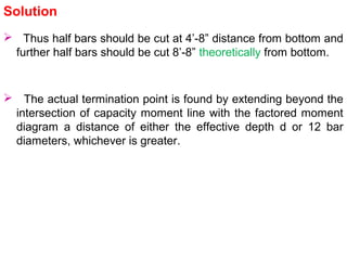
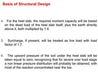
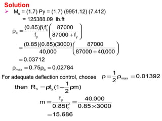
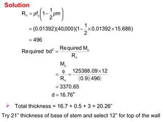
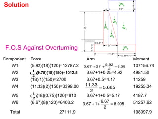
2. Design considerations for retaining walls including stability against overturning, sliding, and settlement; drainage; and structural design basis using load and safety factors.
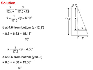
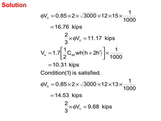
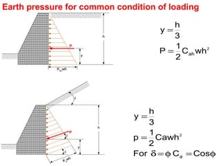
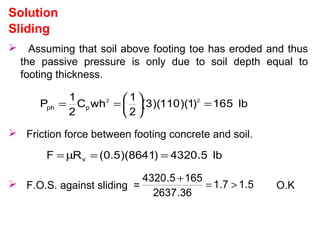
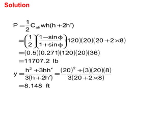
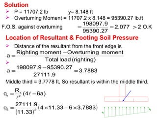
3. An example problem showing calculations for earth pressure, restoring moments, and checking stability of a gravity wall.


![( )[ ]
[ ] [ ]
v
21
2
v
22
v
1
2
v
2
vvv
2,1
3
v
2
v
v
3
v
2
v
v
2,1
3
v
v
2,1
R
qq
2
awhen
2a6
R
q&a64
R
q
a63
RaR6R3R
q
12
4
aR2R
R
12
2
aR
4
R
R
q
12
2
Ra
2R
q
===
−=−=
−±=
−±=
−
±=
−
±=
−
±=
Unit dimension in the direction perpendicular to the paper.
Stability Requirement
Settlement](https://image.slidesharecdn.com/retainingwall-170102190848/85/Retaining-wall-12-320.jpg)


![Design of Heel Cantilever
Wu = (1.7) (120) (8) + (1.4) [18 x 120 + 2 x 150 ]
= 5076 lb/ft
( )( )
ft.lb76.88947
92.576.5
2
1
2
W
M
2
u
2
=
=
=
Vu = Factored shear a joint of stem and heel
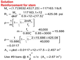
Solution
When the support reaction introduces compression into
the end region, then critical shear is at a distance d
from face of support. However, the support is not
producing compression, therefore, critical shear is at
joint of stem and heel.](https://image.slidesharecdn.com/retainingwall-170102190848/85/Retaining-wall-39-320.jpg)

![Now Wu=(1.7)(120)(8)+(1.4)[(17.5)(120)+(2.5)(150)] = 5097 lb/ft
.ft.lb75.89315)92.5)(5097(
2
1
M 2
u =
=
005.0
f
200
00337.0
f
mR2
11
m
1
psi23.131
)5.27)(12)(9.0(
1289315
bd
M
RquiredRe
y
min
y
n
u
n 22
==ρ
=
−−=ρ
=
×
=
φ
=
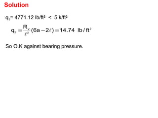
Solution
Design of Heel Cantilever](https://image.slidesharecdn.com/retainingwall-170102190848/85/Retaining-wall-41-320.jpg)