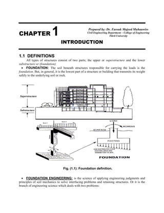
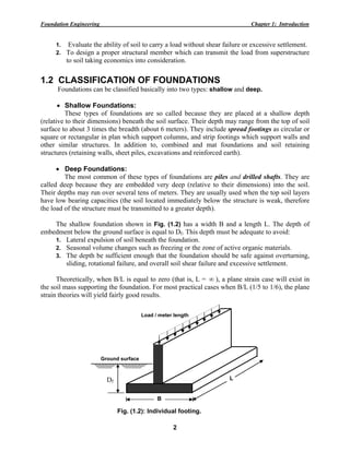
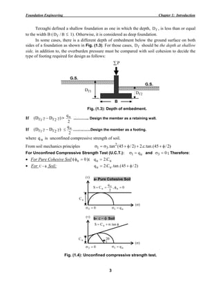
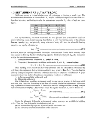
SlideShare a Scribd company logo
CHAPTER 1
INTRODUCTION
1.1 DEFINITIONS
All types of structures consist of two parts; the upper or superstructure and the lower
substructure or (foundation).
• FOUNDATION: The soil beneath structures responsible for carrying the loads is the
foundation. But, in general, it is the lowest part of a structure or building that transmits its weight
safely to the underlying soil or rock.
• FOUNDATION ENGINEERING: is the science of applying engineering judgments and
principles of soil mechanics to solve interfacing problems and retaining structures. Or it is the
branch of engineering science which deals with two problems:
Fig. (1.1): Foundation definition.
T
Superstructure
Substructure
Prepared by: Dr. Farouk Majeed Muhauwiss
Civil Engineering Department – College of Engineering
Tikrit University
Foundation Engineering Chapter 1: Introduction
2
1. Evaluate the ability of soil to carry a load without shear failure or excessive settlement.
2. To design a proper structural member which can transmit the load from superstructure
to soil taking economics into consideration.
1.2 CLASSIFICATION OF FOUNDATIONS
Foundations can be classified basically into two types: shallow and deep.
• Shallow Foundations:
These types of foundations are so called because they are placed at a shallow depth
(relative to their dimensions) beneath the soil surface. Their depth may range from the top of soil
surface to about 3 times the breadth (about 6 meters). They include spread footings as circular or
square or rectangular in plan which support columns, and strip footings which support walls and
other similar structures. In addition to, combined and mat foundations and soil retaining
structures (retaining walls, sheet piles, excavations and reinforced earth).
• Deep Foundations:
The most common of these types of foundations are piles and drilled shafts. They are
called deep because they are embedded very deep (relative to their dimensions) into the soil.
Their depths may run over several tens of meters. They are usually used when the top soil layers
have low bearing capacities (the soil located immediately below the structure is weak, therefore
the load of the structure must be transmitted to a greater depth).
The shallow foundation shown in Fig. (1.2) has a width B and a length L. The depth of
embedment below the ground surface is equal to Df. This depth must be adequate to avoid:
1. Lateral expulsion of soil beneath the foundation.
2. Seasonal volume changes such as freezing or the zone of active organic materials.
3. The depth be sufficient enough that the foundation should be safe against overturning,
sliding, rotational failure, and overall soil shear failure and excessive settlement.
Theoretically, when B/L is equal to zero (that is, L = ∞ ), a plane strain case will exist in
the soil mass supporting the foundation. For most practical cases when B/L (1/5 to 1/6), the plane
strain theories will yield fairly good results.
Df
Fig. (1.2): Individual footing.
Ground surface
B
L
Load / meter length
Foundation Engineering Chapter 1: Introduction
3
Terzaghi defined a shallow foundation as one in which the depth, fD , is less than or equal
to the width B ( B/Df ≤ 1). Otherwise, it is considered as deep foundation.
In some cases, there is a different depth of embedment below the ground surface on both
sides of a foundation as shown in Fig. (1.3). For those cases, fD should be the depth at shallow
side, in addition to, the overburden pressure must be compared with soil cohesion to decide the
type of footing required for design as follows:
If ).D.D( 2f1f γ−γ >
2
qu ……….. Design the member as a retaining wall.
If ).D.D( 2f1f γ−γ
2
qu≤ …………Design the member as a footing.
where uq is unconfined compressive strength of soil.
From soil mechanics principles )2/45.(tan.c.2)2/45(tan. 2
31 φ++φ+σ=σ
For Unconfined Compressive Strength Test (U.C.T.): u1 q=σ and 03 =σ ; Therefore:
• For Pure Cohesive Soil ( 0u =φ ): uu C.2q =
• For φ−C Soil: )2/45.(tan.C.2q uu φ+=
)(σ
)(τ
03 =σ u1 q=σ
uC
φσ+= tan.CS u
θ2
b- φ−c Soil
)(σ
)(τ
03 =σ u1 q=σ
0,
2
q
CS u
u
u =φ==
uC
a- Pure Cohesive Soil
Fig. (1.4): Unconfined compressive strength test.
∑P
G.S.
2fD1fD
B
Fig. (1.3): Depth of embedment.
G.S.
Foundation Engineering Chapter 1: Introduction
4
1.3 SETTLEMENT AT ULTIMATE LOAD
Settlement means a vertical displacement of a structure or footing or road,…etc.. The
settlement of the foundation at ultimate load, uS , is quite variable and depends on several factors.
Based on laboratory and field test results, the approximate ranges for uS values of soils are given
below.
Soil B/Df B/Su (%)
Sand 0 5 to 12
Sand Large 25 to 28
Clay 0 4 to 8
Clay Large 15 to 20
For any foundation, one must ensure that the load per unit area of foundation does not
exceed a limiting value, thereby causing shear failure in soil. This limiting value is the ultimate
bearing capacity, .ultq and generally using a factor of safety of 3 to 4 the allowable bearing
capacity, .allq can be calculated as:
S.F
q
q .ult
.all = …….………………………….…..……….………………..(1.1)
However, based on limiting settlement conditions, there are other factors which must be taken
into account in deriving the allowable bearing capacity. The total settlement, TS , of a foundation
will be the sum of three components:
1. Elastic or immediate settlement, iS ; (major in sand),
2. Primary and Secondary consolidation settlements, cS and csS ; (major in clay).
TS = iS + cS + csS …..…………………………..……………………..(1.2)
Most building codes provide an allowable settlement limit for a foundation which may be
well below the settlement derived corresponding to .allq given by Eq. (1.1). Thus, the bearing
capacity corresponding to the allowable settlement must also be taken into consideration. A given
structure with several shallow foundations may undergo two types of settlement:
1. Uniform or equal total settlement, and
2. Differential settlement.
Fig. (1.5a) shows a uniform settlement which occurs when a structure is built over rigid
structural mat. However, depending on the load of various foundation components, a structure
may experience differential settlement. A foundation may also undergo uniform tilt (Fig. 1.5b) or
non-uniform settlement (Fig. 1.5c). In these cases, the angular distortion, Δ, can be defined as:
L
SS (min)t(max)t
′
−
=Δ (for uniform tilt) …….....…………………..(1.3)
1
(min)t(max)t
L
SS
′
−
=Δ (for non-uniform settlement) ……….………..(1.4)
Limits for allowable differential settlement of various structures are available in building
codes. Thus, the final design of a foundation depends on:
(a) the ultimate bearing capacity, (b) the allowable settlement, and
(c) the allowable differential settlement for the structure.
Foundation Engineering Chapter 1: Introduction
5
Example (1.1):
A 30 cm x 30 cm column is loaded with 40 Ton. Check whether the column can be placed
on soil directly or not if the allowable bearing capacity of soil is:
(a) .allq = 50 kg/cm2
, and
(b) .allq = 1.0 kg/cm2
.
Solution:
(a)
A
Q
q .all =
or 800
50
40000
A == cm2
(minimum required area) < 900 cm2
(area of column)……… O.K.
or 4.44
30x30
40000
q .all == kg/cm2
< 50 kg/cm2
…… O.K.
∴ No failure may happen; and the column can be placed directly on the soil.
(b) 40000
0.1
40000
A == cm2
(minimum required area) > 900 cm2
(area of column) ..... N.O.K.
∴ (Not safe) and the column in this case cannot be placed directly on soil, therefore, an
enlarged base is required.
A = 40000 cm2
= 4 m2
, assuming square area: AB = = √4 = 2m. (see Fig. (1.6)).
Fig. (1.5): Settlement of a structure.
(a) Uniform settlement (b) Uniform tilt (c) Non-uniform settlement
L′ G.S. L′ G.S.
2L′
G.S.
.)(mintS
.)(maxtS
.)(mintS
.)(maxtS
1L′
St St
Fig. (1.6): Solution of example (1.1).
40 Ton
2m
2m
(b) 2
cm/kg.0.1.qall =
40 Ton
(a) 2
cm/kg.50.qall =
30 cm x 30 cm
Foundation Engineering Chapter 1: Introduction
6
1.4 TYPES OF FAILURE IN FOOTINGS
It is possible due to load that a footing fails by one or two of the following:
(1) Shear failure: this failure must be checked against:-
(i) punching shear and (ii) wide beam shear. No shear failure is satisfied by providing an
adequate thickness of concrete (see Fig. 1.7).
(2) Tension failure: this failure decides the locations and positions of steel distribution. No
tension failure is satisfied by providing an adequate steel reinforcement (see Fig. 1.7).
1.5 TYPES OF FOOTINGS
(1) Spread or Isolated or Individual Column Footing:
It is a footing of plain or reinforced concrete that supports a single column. It may be either a
square or circular or rectangular in shape or cross sectional area (see Fig. 1.8). However, the
design of square or circular spread footings is simpler than that of rectangular one. This is evident
due to the twice calculation required for rectangular footing compared with other ones. The
rectangular footing is preferred in case of a moment, since the length is increased in the direction
of moment to make the resultant of loads within the middle third of footing.
(i) Punching shear at (d/2) from face of column.
d/2
L ′′
d/2
d/2
d/2
L′
(c) Internal column:
)LL(2bo ′′+′=
d/2
L ′′
d/2
L′
(b) Corner column:
LLbo ′′+′=
d/2
L ′′
d/2
d/2
L′
(a) External column:
LL2bo ′′+′=
Edgeoffooting
Edgeoffooting
Edge of footing
(ii) Wide beam shear at (d) from face of column.
d
.ultq
uM uM
(iii) Bending moment.
Centerline
Fig. (1.7): Types of failure in footing.
d
d
Square footing Rectangular footingCircular footing
AB =B
B B
L
Fig. (1.8): Spread footing.
Foundation Engineering Chapter 1: Introduction
7
(2) Combined Footing (reinforced concrete only):
It is a footing that connects several columns and can take one of the following shapes:
• Rectangular Combined Footing (see Fig. 1.9):
(a) Used along the walls of building at property lines where the footing for a wall column
can not extend outside the limits of the structure.
(b) If the loads from several columns are transmitted to the same footing, the footing should
be proportioned so that its centroid coincides with the center of gravity of the column
loads.
• Trapezoidal Combined Footing (see Fig. 1.10):
(a) If the maximum load exists at the exterior column,
(b) It is not possible to make the resultant of loads passes through the centroid of the footing.
(i.e., If
2
L
> x >
3
L
).
• Strap or Cantilever Combined Footing (see Fig. 1.11):
(a) If there is an eccentricity, and/ or
(b) If ( x <
3
L
).
a
x′
Pu2
Pu1
b
c. g.
x
S
Propertyline
L
Resultant
Col. 2: 0.4 m x 0.4 m
DL= 385 kN
LL= 270 kN
Col. 1: 0.4 m x 0.4 m
DL= 190 kN
LL= 300 kN
strapd
footingd
e = 0.65
m
0.15 m
5.5 m
Resultant
Fig. (1.10): Trapezoidal combined footing. Fig. (1.11): Strap combined footing.
Col. 1 Col. 2
800 kN
0.5m
0.5m
1200 kN
4.0m 1.3m
0.3m x 0.3m 0.4m x 0.4m
Property line
Soil pressure
Fig. (1.9: Rectangular combined footing.
Foundation Engineering Chapter 1: Introduction
8
(3) Wall or Strip Footing (plain or reinforced concrete only) (see Fig. 1.12):
This footing represents a plain strain condition, such as a footing beneath a wall. In this case,
the footing area is calculated as:
.allq
length..unit/load..Total
1.x.BArea ==
(4) Raft Foundation (see Fig. 1.13):
Is a combined footing that covers the entire area beneath a structure and supports all the
walls and columns, such that: appliedq
A
Q
=
∑
< .allq
It is used when:
• All spread footings areas represent greater than 50 % of the entire site area,
• If there is a basement and ground water table problems,
• The bearing capacity of soil is very low, and the building loads are so heavy, and
• A large differential settlement is expected to occur.
F
8 m8 m
0.25 m0.25 m
H E J D
A
4.25 m
CG B I
4.25 m
y′
x′
8 m
0.25 m
0.25 m
7 m
7 m
7 m
400 kN 500 kN 450 kN
1500 kN 1500 kN 1200 kN
400 kN 500 kN 350 kN
Fig. (1.13): Raft foundation.
Sand
Q = 200 kN/m
0.75m
mγ = 18 kN/m
3
ω=10%, Gs = 2.65
1.5m
Q / meter length
fD
B
Wall footing Wall footingW.T.
Fig. (1.12): Wall footing.
c′ = 0 , °=φ ′ 30
Foundation Engineering Chapter 1: Introduction
9
(5) Pile Foundation (see Fig. 1.14):
Pile is a structural member made of wood, steel or concrete used to transmit the load from
superstructure to underlying soil stratum in the following cases:
• When the soil profile consists of weak compressible soils,
• If .allapplied q....q > ,
• To resist tension or uplift forces induced by horizontal forces acting on superstructure
due to wind or earthquakes loads.
Piles usually are of two types:
(a) Driven piles, suitable for granular soils,
(b) Bored piles, suitable for clayey soils,
Each type of these piles can be made of precast concrete or cast in place.
(6) Pier Foundation (see Fig. 1.15):
It is an underground structural member that serves the same purpose as a footing. However,
the ratio of the depth of foundation to the base width of piers is usually greater than 4 (Df /B >4),
whereas, for footings this ratio is commonly less than unity (Df /B ≤1). A drilled pier is a
cylindrical column that has essentially the same function as piles. The drilled pier foundation is
used to transfer the structural load from the upper unstable soils to the lower firm stratum.
G.S.
Hard stratum
Total load, Q
(a) Single Pile
Skin friction, Qs
End bearing, Qb
Pile Cap
m Piles
G.S.
n Piles
S
b
a
S
Total load
(b) Layout of Piles in groups.
L
Fig. (1.14): Single and group piles.
Foundatio
A
foundatio
base of a
firm stra
piles. A
bridge a
pressure
Ess
same pur
the meth
installed
drilling. I
support
resisted b
(7) Float
If th
excavated
satisfied,
(8) Reta
Ret
natural s
differenc
commonl
of bridge
There are
requirem
(a) Grav
most
const
(b) Semi
reinf
(c) Canti
heigh
desig
indiv
(d) Coun
howe
the w
econ
(e) Butt
braci
n Engineering
part of t
on is known
a pier shaft
atum or it m
pier shaft lo
and subjec
is known as
entially, pie
rpose. The d
hod of ins
by driving
In general, a
the same
by group of p
ting Foun
he weight o
d soil a foun
it is conside
aining Wall
taining walls
lopes. In ge
e in the ele
ly supported
e abutments
e many type
ents. They're
ity Retainin
tly on their
truction is n
i-Gravity Re
forcing steel
ilever Retai
ht up to 8m.
gned as, can
vidual parts (
nterfort Ret
ever, they ha
wall and b
nomical when
tress Retai
ing is in fron
g
the pier a
n as a pier
may rest dir
may be sup
ocated at th
ted to lat
an abutmen
ers and piles
distinction i
stallation. A
and a pier
a single pier
heavy col
piles.
dation:
of the constr
ndation is kn
ered as semi
s:
s are structu
eneral, they
evation of th
d by soil (or
and where
es of retaini
e mainly cla
ng Walls are
own weigh
not economic
etaining Wa
are introduc
ning Walls
It derives it
ntilever beam
(see Fig. 1.1
taining Wal
ave thin vert
base slab to
n the wall he
ining Walls
nt of the wal
above the
shaft. The
rectly on a
pported on
he end of a
teral earth
nt.
s serve the
s based on
A pile is
r by auger
r is used to
lumn load
ructed struct
nown as fully
-compensate
ures used to
are used to
he ground s
rock) under
water may
ing walls, e
assified accor
e constructe
ht and any
cal for walls
alls are mod
ced. This hel
are the mos
ts name from
ms. The stab
16c).
ls are simila
tical concrete
ogether and
eight exceed
s this type i
l and is in co
10
ture or build
y compensat
ed foundatio
provide stab
o support so
surface on e
rlying the ba
undercut th
ach type se
rding to its b
ed of plain c
soil resting
higher than
dification of
lps minimizi
st common t
m the fact th
bility of this
ar to cantile
e slabs behin
reduce the
ds 8m (see F
is similar to
ompression i
ding equal t
ed foundatio
on.
bility for ear
oil banks an
each of wal
ase slab, or s
he base soil
rves differe
behavior aga
concrete or s
on the wal
3m (see Fig
f gravity wal
ing the wall
type of retai
hat its indivi
s type is a fu
ever retainin
nd the wall k
e shear and
ig. 1.16d).
o counterfor
instead of te
Fig. (1.15
Chap
o the weigh
on. But if thi
rth or other
nd water or
ll sides. Ret
supported on
as in water
nt purposes
ainst the soil
stone mason
ll for stabili
g. 1.16a).
ll in which s
section (see
ining walls t
dual parts b
unction of th
ng walls, at
known as co
d bending m
rt retaining
ension.
5): Pier foun
pter 1: Introd
ht of the rep
is condition
materials at
also to mai
taining wall
n piles; as in
r front struc
and fit diff
l as:
nry. They de
ity. This typ
small amoun
Fig. 1.16b)
that used for
ehave as, an
he strength
regular inte
ounterforts th
moment. Th
wall, excep
ndations.
duction
placed
is not
t their
intain
ls are
n case
tures.
ferent
epend
pe of
nts of
).
r wall
nd are
of its
rvals,
hat tie
hey're
pt the
Foundation Engineering Chapter 1: Introduction
11
(f) Bridge Abutments are special type of retaining walls, not only containing the approach fill,
but serving as a support for the bridge superstructure (see Fig. 1.16f).
(g) Crib Walls are built-up members of pieces of precast concrete, metal, or timber and are
supported by anchor pieces embedded in the soil for stability (see Fig. 1.16g).
Among these walls, only the cantilever retaining walls and bridge abutments are much used.
(b) Semi-gravity wall
(f) Bridge abutment (g) Crib walls
Fig. (1.16): Common types of retaining walls.
(c) Cantilever wall (d) Counterfort wall
(a) Gravity walls
Foundation Engineering Chapter 1: Introduction
12
(9) Sheet Piles Walls:
These are classified as; anchored and cantilevered sheet pile walls; each kind of them may be
used in single or double sheets walls.
(a) Cantilever or Free Sheet-Pile Walls are constructed by driving a sheet pile to a depth
sufficient to develop a cantilever beam type reaction to resist the active pressures on the wall.
That is, the embedment length which must be adequate to resist both lateral forces as well as
a bending moment (see Fig. 1.17a).
(b) Anchored or Fixed Sheet-Pile Walls are types of retaining walls found in waterfront
construction, which are used to form wharves or piers for loading and unloading ships (see
Fig. 1.17b).
(10) Caissons:
A hollow shaft or box with sharp ends or cutting edges for ease penetrating into soil used to
isolate the site of project from the surrounding area. The material inside the caisson is removed
by dredged through openings in the top or by hand excavation. Whereas, the lower part of it may
be sealed from atmosphere and filled with air under pressure to exclude water from work space
(see Fig. 1.18).
(b) Anchored sheet pile wall.
Dredge line
sq
C
H
D
A
B
Anchor tie rod
(a) Cantilever sheet pile wall.
C
B
A
H
D
Dredge line
Point of rotation
Fig. (1.17): Types of sheet piling walls.
Fig. (1.18): Methods of caisson construction.
(a) The Chicago method. (b) The Gow method.
Foundation Engineering Chapter 1: Introduction
13
(11) Cofferdams:
(a) Single and Double Sheet Pile Cofferdams: used for depth of water not exceeds 3.0 m.
(b) Cellular Cofferdams: used for higher depths of water, i.e., greater than 3.0 m.
These are relatively watertight enclosures of wood or steel sheet piles. Before the cofferdam
is pumped out, one set of bracing is installed just above the water line. The water level is then
lowered to the elevation at which another set of bracing must be installed. Successive lowering of
water level and installation of bracing continue until the cofferdam is pumped out (see Fig. 1.19).
Fig. (1.19: Cellular cofferdams.
(a) Circular, economical for deep cells.
(b) Diaphragm, economical in quiet water. (c) Modified circular.
°45
°45
°30 °30

More Related Content

What's hot

Unit 1 sheet pile-converted
Unit 1   sheet pile-convertedUnit 1   sheet pile-converted
Unit 1 sheet pile-converted
Nigitha rajan
 
Retaining walls (الجدران الاستنادية)-steel sheet piles - sheet piles wall
Retaining walls (الجدران الاستنادية)-steel sheet piles - sheet piles wallRetaining walls (الجدران الاستنادية)-steel sheet piles - sheet piles wall
Retaining walls (الجدران الاستنادية)-steel sheet piles - sheet piles wall
Dr.Youssef Hammida
 
Chapter 19
Chapter 19Chapter 19
Chapter 19
SantistebanCampos
 
Lecture 8 raft foundation
Lecture 8 raft foundationLecture 8 raft foundation
Lecture 8 raft foundation
Dr.Abdulmannan Orabi
 
Lecture17
Lecture17Lecture17
Lecture17
Wildcat23
 
Chapter 16
Chapter 16Chapter 16
Chapter 16
SantistebanCampos
 
Retaining wall(الجدران الاستنادية).- Scant Piles
Retaining wall(الجدران الاستنادية).- Scant PilesRetaining wall(الجدران الاستنادية).- Scant Piles
Retaining wall(الجدران الاستنادية).- Scant Piles
Dr.youssef hamida
 
An Approximate Analysis Procedure for Piled Raft subjected to Vertical Loading
An Approximate Analysis Procedure for Piled Raft subjected to Vertical LoadingAn Approximate Analysis Procedure for Piled Raft subjected to Vertical Loading
An Approximate Analysis Procedure for Piled Raft subjected to Vertical Loading
ijsrd.com
 
Top schools in delhi ncr
Top schools in delhi ncrTop schools in delhi ncr
Top schools in delhi ncr
Edhole.com
 
Pile design summary of ø450, ø600, ø750 and ø900 12, 15 and 20m long -
Pile design summary of ø450, ø600, ø750 and ø900 12, 15 and 20m long -Pile design summary of ø450, ø600, ø750 and ø900 12, 15 and 20m long -
Pile design summary of ø450, ø600, ø750 and ø900 12, 15 and 20m long -
Prakash Rawal
 
Behavior of piled raft foundation
Behavior of piled raft foundationBehavior of piled raft foundation
Behavior of piled raft foundationmfayyaz2000
 
Chapter 14
Chapter 14Chapter 14
Chapter 14
SantistebanCampos
 
Design of shallow foundation slide share
Design of shallow foundation   slide shareDesign of shallow foundation   slide share
Design of shallow foundation slide share
zameer1979
 
Chapter 11
Chapter 11Chapter 11
Chapter 11
SantistebanCampos
 
ultimate bearing capacity of shallow foundations: special cases
ultimate bearing capacity of shallow foundations: special casesultimate bearing capacity of shallow foundations: special cases
ultimate bearing capacity of shallow foundations: special casesMehmet Akin
 
Design of a circular raft for a cylindrical core
Design of a circular raft for a cylindrical coreDesign of a circular raft for a cylindrical core
Design of a circular raft for a cylindrical core
Amin El Gendy, Ph.D., P.Eng, PMP
 
4.0 bearing capacity shallow foundations
4.0 bearing capacity shallow foundations4.0 bearing capacity shallow foundations
4.0 bearing capacity shallow foundations
Rakesh Reddy
 
Basics of Foundation Engineering هندسة الأساسات & Eng. Ahmed S. Al-Agha
Basics of Foundation Engineering هندسة الأساسات & Eng. Ahmed S. Al-AghaBasics of Foundation Engineering هندسة الأساسات & Eng. Ahmed S. Al-Agha
Basics of Foundation Engineering هندسة الأساسات & Eng. Ahmed S. Al-Agha
Hossam Shafiq II
 
Lecture 2 bearing capacity
Lecture 2 bearing capacityLecture 2 bearing capacity
Lecture 2 bearing capacity
Dr.Abdulmannan Orabi
 

What's hot (20)

Unit 1 sheet pile-converted
Unit 1   sheet pile-convertedUnit 1   sheet pile-converted
Unit 1 sheet pile-converted
 
Retaining walls (الجدران الاستنادية)-steel sheet piles - sheet piles wall
Retaining walls (الجدران الاستنادية)-steel sheet piles - sheet piles wallRetaining walls (الجدران الاستنادية)-steel sheet piles - sheet piles wall
Retaining walls (الجدران الاستنادية)-steel sheet piles - sheet piles wall
 
Chapter 19
Chapter 19Chapter 19
Chapter 19
 
Lecture 8 raft foundation
Lecture 8 raft foundationLecture 8 raft foundation
Lecture 8 raft foundation
 
05 chapter 6 mat foundations
05 chapter 6 mat foundations05 chapter 6 mat foundations
05 chapter 6 mat foundations
 
Lecture17
Lecture17Lecture17
Lecture17
 
Chapter 16
Chapter 16Chapter 16
Chapter 16
 
Retaining wall(الجدران الاستنادية).- Scant Piles
Retaining wall(الجدران الاستنادية).- Scant PilesRetaining wall(الجدران الاستنادية).- Scant Piles
Retaining wall(الجدران الاستنادية).- Scant Piles
 
An Approximate Analysis Procedure for Piled Raft subjected to Vertical Loading
An Approximate Analysis Procedure for Piled Raft subjected to Vertical LoadingAn Approximate Analysis Procedure for Piled Raft subjected to Vertical Loading
An Approximate Analysis Procedure for Piled Raft subjected to Vertical Loading
 
Top schools in delhi ncr
Top schools in delhi ncrTop schools in delhi ncr
Top schools in delhi ncr
 
Pile design summary of ø450, ø600, ø750 and ø900 12, 15 and 20m long -
Pile design summary of ø450, ø600, ø750 and ø900 12, 15 and 20m long -Pile design summary of ø450, ø600, ø750 and ø900 12, 15 and 20m long -
Pile design summary of ø450, ø600, ø750 and ø900 12, 15 and 20m long -
 
Behavior of piled raft foundation
Behavior of piled raft foundationBehavior of piled raft foundation
Behavior of piled raft foundation
 
Chapter 14
Chapter 14Chapter 14
Chapter 14
 
Design of shallow foundation slide share
Design of shallow foundation   slide shareDesign of shallow foundation   slide share
Design of shallow foundation slide share
 
Chapter 11
Chapter 11Chapter 11
Chapter 11
 
ultimate bearing capacity of shallow foundations: special cases
ultimate bearing capacity of shallow foundations: special casesultimate bearing capacity of shallow foundations: special cases
ultimate bearing capacity of shallow foundations: special cases
 
Design of a circular raft for a cylindrical core
Design of a circular raft for a cylindrical coreDesign of a circular raft for a cylindrical core
Design of a circular raft for a cylindrical core
 
4.0 bearing capacity shallow foundations
4.0 bearing capacity shallow foundations4.0 bearing capacity shallow foundations
4.0 bearing capacity shallow foundations
 
Basics of Foundation Engineering هندسة الأساسات & Eng. Ahmed S. Al-Agha
Basics of Foundation Engineering هندسة الأساسات & Eng. Ahmed S. Al-AghaBasics of Foundation Engineering هندسة الأساسات & Eng. Ahmed S. Al-Agha
Basics of Foundation Engineering هندسة الأساسات & Eng. Ahmed S. Al-Agha
 
Lecture 2 bearing capacity
Lecture 2 bearing capacityLecture 2 bearing capacity
Lecture 2 bearing capacity
 

Similar to Ch1 introduction

Raft foundations
Raft foundationsRaft foundations
Raft foundations
hatim ahmed
 
Lecture 1. bearing capacity of soil
Lecture 1. bearing capacity of soilLecture 1. bearing capacity of soil
Lecture 1. bearing capacity of soil
husseinhadi2
 
Foundation (2)
Foundation (2)Foundation (2)
Foundation (2)
topukuet
 
BEARING CAPASITY OFSOIL.ppt
BEARING CAPASITY OFSOIL.pptBEARING CAPASITY OFSOIL.ppt
BEARING CAPASITY OFSOIL.ppt
SamuelGetiye
 
BEARING CAPASITY OFSOIL.ppt
BEARING CAPASITY OFSOIL.pptBEARING CAPASITY OFSOIL.ppt
BEARING CAPASITY OFSOIL.ppt
sjshukla
 
BEARING CAPASITY OFSOIL.ppt
BEARING CAPASITY OFSOIL.pptBEARING CAPASITY OFSOIL.ppt
BEARING CAPASITY OFSOIL.ppt
jamvantsolanki
 
lecturenote_1463116827CHAPTER-II-BEARING CAPACITY OF FOUNDATION SOIL.pdf
lecturenote_1463116827CHAPTER-II-BEARING CAPACITY OF FOUNDATION SOIL.pdflecturenote_1463116827CHAPTER-II-BEARING CAPACITY OF FOUNDATION SOIL.pdf
lecturenote_1463116827CHAPTER-II-BEARING CAPACITY OF FOUNDATION SOIL.pdf
2cd
 
Soil Bearing Capacity.pdf
Soil Bearing Capacity.pdfSoil Bearing Capacity.pdf
Soil Bearing Capacity.pdf
theceeshops
 
Bearing-Capacity-part
Bearing-Capacity-partBearing-Capacity-part
Bearing-Capacity-part
AwaisArshad48
 
Bearing capasity of soil
Bearing capasity of soilBearing capasity of soil
Bearing capasity of soil
mohaammed abdulmajid
 
pilefoundation_16th aug.ppt
pilefoundation_16th aug.pptpilefoundation_16th aug.ppt
pilefoundation_16th aug.ppt
FREELANCER
 
Foundation Engineering
Foundation EngineeringFoundation Engineering
Foundation Engineering
Sachin Kulkarni
 
5. TPES AND DESIGN OF FOOTING in rcc.pptx
5. TPES AND DESIGN OF FOOTING in rcc.pptx5. TPES AND DESIGN OF FOOTING in rcc.pptx
5. TPES AND DESIGN OF FOOTING in rcc.pptx
venkateshreddytab
 
FootingDesign.pptx
FootingDesign.pptxFootingDesign.pptx
FootingDesign.pptx
SolomonAlemu28
 
CE-Raft-Foundation.pdf
CE-Raft-Foundation.pdfCE-Raft-Foundation.pdf
CE-Raft-Foundation.pdf
JeevanandanKanagavel1
 
Shallow foundation(by indrajit mitra)01
Shallow   foundation(by indrajit mitra)01Shallow   foundation(by indrajit mitra)01
Shallow foundation(by indrajit mitra)01
Indrajit Ind
 
Bearing capacity ch#05(geotech)
Bearing capacity ch#05(geotech)Bearing capacity ch#05(geotech)
Bearing capacity ch#05(geotech)Irfan Malik
 
Bearing capacity
Bearing capacityBearing capacity
Bearing capacity
Bhanu Ojha
 

Similar to Ch1 introduction (20)

Raft foundations
Raft foundationsRaft foundations
Raft foundations
 
Lecture 1. bearing capacity of soil
Lecture 1. bearing capacity of soilLecture 1. bearing capacity of soil
Lecture 1. bearing capacity of soil
 
Foundation (2)
Foundation (2)Foundation (2)
Foundation (2)
 
BEARING CAPASITY OFSOIL.ppt
BEARING CAPASITY OFSOIL.pptBEARING CAPASITY OFSOIL.ppt
BEARING CAPASITY OFSOIL.ppt
 
BEARING CAPASITY OFSOIL.ppt
BEARING CAPASITY OFSOIL.pptBEARING CAPASITY OFSOIL.ppt
BEARING CAPASITY OFSOIL.ppt
 
BEARING CAPASITY OFSOIL.ppt
BEARING CAPASITY OFSOIL.pptBEARING CAPASITY OFSOIL.ppt
BEARING CAPASITY OFSOIL.ppt
 
lecturenote_1463116827CHAPTER-II-BEARING CAPACITY OF FOUNDATION SOIL.pdf
lecturenote_1463116827CHAPTER-II-BEARING CAPACITY OF FOUNDATION SOIL.pdflecturenote_1463116827CHAPTER-II-BEARING CAPACITY OF FOUNDATION SOIL.pdf
lecturenote_1463116827CHAPTER-II-BEARING CAPACITY OF FOUNDATION SOIL.pdf
 
Soil Bearing Capacity.pdf
Soil Bearing Capacity.pdfSoil Bearing Capacity.pdf
Soil Bearing Capacity.pdf
 
Bearing-Capacity-part
Bearing-Capacity-partBearing-Capacity-part
Bearing-Capacity-part
 
Bearing capasity of soil
Bearing capasity of soilBearing capasity of soil
Bearing capasity of soil
 
pilefoundation_16th aug.ppt
pilefoundation_16th aug.pptpilefoundation_16th aug.ppt
pilefoundation_16th aug.ppt
 
Pile foundation
Pile foundationPile foundation
Pile foundation
 
Foundation Engineering
Foundation EngineeringFoundation Engineering
Foundation Engineering
 
5. TPES AND DESIGN OF FOOTING in rcc.pptx
5. TPES AND DESIGN OF FOOTING in rcc.pptx5. TPES AND DESIGN OF FOOTING in rcc.pptx
5. TPES AND DESIGN OF FOOTING in rcc.pptx
 
FootingDesign.pptx
FootingDesign.pptxFootingDesign.pptx
FootingDesign.pptx
 
CE-Raft-Foundation.pdf
CE-Raft-Foundation.pdfCE-Raft-Foundation.pdf
CE-Raft-Foundation.pdf
 
Shallow foundation(by indrajit mitra)01
Shallow   foundation(by indrajit mitra)01Shallow   foundation(by indrajit mitra)01
Shallow foundation(by indrajit mitra)01
 
Bearing capacity ch#05(geotech)
Bearing capacity ch#05(geotech)Bearing capacity ch#05(geotech)
Bearing capacity ch#05(geotech)
 
Bearing capacity
Bearing capacityBearing capacity
Bearing capacity
 
Presentation
PresentationPresentation
Presentation
 

More from Reyam AL Mousawi

173868297 mouth-washes-3
173868297 mouth-washes-3173868297 mouth-washes-3
173868297 mouth-washes-3
Reyam AL Mousawi
 
316691663 pile-foundations-lecture-note-1-pdf
316691663 pile-foundations-lecture-note-1-pdf316691663 pile-foundations-lecture-note-1-pdf
316691663 pile-foundations-lecture-note-1-pdf
Reyam AL Mousawi
 
Two dimensional flow
Two dimensional flowTwo dimensional flow
Two dimensional flow
Reyam AL Mousawi
 
Strength of materials
Strength of materialsStrength of materials
Strength of materials
Reyam AL Mousawi
 
W.h.mosley, j.h.bungey. reinforced concrete design book
W.h.mosley, j.h.bungey. reinforced concrete design bookW.h.mosley, j.h.bungey. reinforced concrete design book
W.h.mosley, j.h.bungey. reinforced concrete design book
Reyam AL Mousawi
 

More from Reyam AL Mousawi (6)

173868297 mouth-washes-3
173868297 mouth-washes-3173868297 mouth-washes-3
173868297 mouth-washes-3
 
316691663 pile-foundations-lecture-note-1-pdf
316691663 pile-foundations-lecture-note-1-pdf316691663 pile-foundations-lecture-note-1-pdf
316691663 pile-foundations-lecture-note-1-pdf
 
Download
DownloadDownload
Download
 
Two dimensional flow
Two dimensional flowTwo dimensional flow
Two dimensional flow
 
Strength of materials
Strength of materialsStrength of materials
Strength of materials
 
W.h.mosley, j.h.bungey. reinforced concrete design book
W.h.mosley, j.h.bungey. reinforced concrete design bookW.h.mosley, j.h.bungey. reinforced concrete design book
W.h.mosley, j.h.bungey. reinforced concrete design book
 

Recently uploaded

Standard Reomte Control Interface - Neometrix
Standard Reomte Control Interface - NeometrixStandard Reomte Control Interface - Neometrix
Standard Reomte Control Interface - Neometrix
Neometrix_Engineering_Pvt_Ltd
 
weather web application report.pdf
weather web application report.pdfweather web application report.pdf
weather web application report.pdf
Pratik Pawar
 
Hybrid optimization of pumped hydro system and solar- Engr. Abdul-Azeez.pdf
Hybrid optimization of pumped hydro system and solar- Engr. Abdul-Azeez.pdfHybrid optimization of pumped hydro system and solar- Engr. Abdul-Azeez.pdf
Hybrid optimization of pumped hydro system and solar- Engr. Abdul-Azeez.pdf
fxintegritypublishin
 
MCQ Soil mechanics questions (Soil shear strength).pdf
MCQ Soil mechanics questions (Soil shear strength).pdfMCQ Soil mechanics questions (Soil shear strength).pdf
MCQ Soil mechanics questions (Soil shear strength).pdf
Osamah Alsalih
 
CW RADAR, FMCW RADAR, FMCW ALTIMETER, AND THEIR PARAMETERS
CW RADAR, FMCW RADAR, FMCW ALTIMETER, AND THEIR PARAMETERSCW RADAR, FMCW RADAR, FMCW ALTIMETER, AND THEIR PARAMETERS
CW RADAR, FMCW RADAR, FMCW ALTIMETER, AND THEIR PARAMETERS
veerababupersonal22
 
DESIGN A COTTON SEED SEPARATION MACHINE.docx
DESIGN A COTTON SEED SEPARATION MACHINE.docxDESIGN A COTTON SEED SEPARATION MACHINE.docx
DESIGN A COTTON SEED SEPARATION MACHINE.docx
FluxPrime1
 
Design and Analysis of Algorithms-DP,Backtracking,Graphs,B&B
Design and Analysis of Algorithms-DP,Backtracking,Graphs,B&BDesign and Analysis of Algorithms-DP,Backtracking,Graphs,B&B
Design and Analysis of Algorithms-DP,Backtracking,Graphs,B&B
Sreedhar Chowdam
 
Building Electrical System Design & Installation
Building Electrical System Design & InstallationBuilding Electrical System Design & Installation
Building Electrical System Design & Installation
symbo111
 
block diagram and signal flow graph representation
block diagram and signal flow graph representationblock diagram and signal flow graph representation
block diagram and signal flow graph representation
Divya Somashekar
 
Cosmetic shop management system project report.pdf
Cosmetic shop management system project report.pdfCosmetic shop management system project report.pdf
Cosmetic shop management system project report.pdf
Kamal Acharya
 
Industrial Training at Shahjalal Fertilizer Company Limited (SFCL)
Industrial Training at Shahjalal Fertilizer Company Limited (SFCL)Industrial Training at Shahjalal Fertilizer Company Limited (SFCL)
Industrial Training at Shahjalal Fertilizer Company Limited (SFCL)
MdTanvirMahtab2
 
Recycled Concrete Aggregate in Construction Part III
Recycled Concrete Aggregate in Construction Part IIIRecycled Concrete Aggregate in Construction Part III
Recycled Concrete Aggregate in Construction Part III
Aditya Rajan Patra
 
Water Industry Process Automation and Control Monthly - May 2024.pdf
Water Industry Process Automation and Control Monthly - May 2024.pdfWater Industry Process Automation and Control Monthly - May 2024.pdf
Water Industry Process Automation and Control Monthly - May 2024.pdf
Water Industry Process Automation & Control
 
Final project report on grocery store management system..pdf
Final project report on grocery store management system..pdfFinal project report on grocery store management system..pdf
Final project report on grocery store management system..pdf
Kamal Acharya
 
HYDROPOWER - Hydroelectric power generation
HYDROPOWER - Hydroelectric power generationHYDROPOWER - Hydroelectric power generation
HYDROPOWER - Hydroelectric power generation
Robbie Edward Sayers
 
6th International Conference on Machine Learning & Applications (CMLA 2024)
6th International Conference on Machine Learning & Applications (CMLA 2024)6th International Conference on Machine Learning & Applications (CMLA 2024)
6th International Conference on Machine Learning & Applications (CMLA 2024)
ClaraZara1
 
Fundamentals of Electric Drives and its applications.pptx
Fundamentals of Electric Drives and its applications.pptxFundamentals of Electric Drives and its applications.pptx
Fundamentals of Electric Drives and its applications.pptx
manasideore6
 
14 Template Contractual Notice - EOT Application
14 Template Contractual Notice - EOT Application14 Template Contractual Notice - EOT Application
14 Template Contractual Notice - EOT Application
SyedAbiiAzazi1
 
CME397 Surface Engineering- Professional Elective
CME397 Surface Engineering- Professional ElectiveCME397 Surface Engineering- Professional Elective
CME397 Surface Engineering- Professional Elective
karthi keyan
 
Immunizing Image Classifiers Against Localized Adversary Attacks
Immunizing Image Classifiers Against Localized Adversary AttacksImmunizing Image Classifiers Against Localized Adversary Attacks
Immunizing Image Classifiers Against Localized Adversary Attacks
gerogepatton
 

Recently uploaded (20)

Standard Reomte Control Interface - Neometrix
Standard Reomte Control Interface - NeometrixStandard Reomte Control Interface - Neometrix
Standard Reomte Control Interface - Neometrix
 
weather web application report.pdf
weather web application report.pdfweather web application report.pdf
weather web application report.pdf
 
Hybrid optimization of pumped hydro system and solar- Engr. Abdul-Azeez.pdf
Hybrid optimization of pumped hydro system and solar- Engr. Abdul-Azeez.pdfHybrid optimization of pumped hydro system and solar- Engr. Abdul-Azeez.pdf
Hybrid optimization of pumped hydro system and solar- Engr. Abdul-Azeez.pdf
 
MCQ Soil mechanics questions (Soil shear strength).pdf
MCQ Soil mechanics questions (Soil shear strength).pdfMCQ Soil mechanics questions (Soil shear strength).pdf
MCQ Soil mechanics questions (Soil shear strength).pdf
 
CW RADAR, FMCW RADAR, FMCW ALTIMETER, AND THEIR PARAMETERS
CW RADAR, FMCW RADAR, FMCW ALTIMETER, AND THEIR PARAMETERSCW RADAR, FMCW RADAR, FMCW ALTIMETER, AND THEIR PARAMETERS
CW RADAR, FMCW RADAR, FMCW ALTIMETER, AND THEIR PARAMETERS
 
DESIGN A COTTON SEED SEPARATION MACHINE.docx
DESIGN A COTTON SEED SEPARATION MACHINE.docxDESIGN A COTTON SEED SEPARATION MACHINE.docx
DESIGN A COTTON SEED SEPARATION MACHINE.docx
 
Design and Analysis of Algorithms-DP,Backtracking,Graphs,B&B
Design and Analysis of Algorithms-DP,Backtracking,Graphs,B&BDesign and Analysis of Algorithms-DP,Backtracking,Graphs,B&B
Design and Analysis of Algorithms-DP,Backtracking,Graphs,B&B
 
Building Electrical System Design & Installation
Building Electrical System Design & InstallationBuilding Electrical System Design & Installation
Building Electrical System Design & Installation
 
block diagram and signal flow graph representation
block diagram and signal flow graph representationblock diagram and signal flow graph representation
block diagram and signal flow graph representation
 
Cosmetic shop management system project report.pdf
Cosmetic shop management system project report.pdfCosmetic shop management system project report.pdf
Cosmetic shop management system project report.pdf
 
Industrial Training at Shahjalal Fertilizer Company Limited (SFCL)
Industrial Training at Shahjalal Fertilizer Company Limited (SFCL)Industrial Training at Shahjalal Fertilizer Company Limited (SFCL)
Industrial Training at Shahjalal Fertilizer Company Limited (SFCL)
 
Recycled Concrete Aggregate in Construction Part III
Recycled Concrete Aggregate in Construction Part IIIRecycled Concrete Aggregate in Construction Part III
Recycled Concrete Aggregate in Construction Part III
 
Water Industry Process Automation and Control Monthly - May 2024.pdf
Water Industry Process Automation and Control Monthly - May 2024.pdfWater Industry Process Automation and Control Monthly - May 2024.pdf
Water Industry Process Automation and Control Monthly - May 2024.pdf
 
Final project report on grocery store management system..pdf
Final project report on grocery store management system..pdfFinal project report on grocery store management system..pdf
Final project report on grocery store management system..pdf
 
HYDROPOWER - Hydroelectric power generation
HYDROPOWER - Hydroelectric power generationHYDROPOWER - Hydroelectric power generation
HYDROPOWER - Hydroelectric power generation
 
6th International Conference on Machine Learning & Applications (CMLA 2024)
6th International Conference on Machine Learning & Applications (CMLA 2024)6th International Conference on Machine Learning & Applications (CMLA 2024)
6th International Conference on Machine Learning & Applications (CMLA 2024)
 
Fundamentals of Electric Drives and its applications.pptx
Fundamentals of Electric Drives and its applications.pptxFundamentals of Electric Drives and its applications.pptx
Fundamentals of Electric Drives and its applications.pptx
 
14 Template Contractual Notice - EOT Application
14 Template Contractual Notice - EOT Application14 Template Contractual Notice - EOT Application
14 Template Contractual Notice - EOT Application
 
CME397 Surface Engineering- Professional Elective
CME397 Surface Engineering- Professional ElectiveCME397 Surface Engineering- Professional Elective
CME397 Surface Engineering- Professional Elective
 
Immunizing Image Classifiers Against Localized Adversary Attacks
Immunizing Image Classifiers Against Localized Adversary AttacksImmunizing Image Classifiers Against Localized Adversary Attacks
Immunizing Image Classifiers Against Localized Adversary Attacks
 

Ch1 introduction

  • 1. CHAPTER 1 INTRODUCTION 1.1 DEFINITIONS All types of structures consist of two parts; the upper or superstructure and the lower substructure or (foundation). • FOUNDATION: The soil beneath structures responsible for carrying the loads is the foundation. But, in general, it is the lowest part of a structure or building that transmits its weight safely to the underlying soil or rock. • FOUNDATION ENGINEERING: is the science of applying engineering judgments and principles of soil mechanics to solve interfacing problems and retaining structures. Or it is the branch of engineering science which deals with two problems: Fig. (1.1): Foundation definition. T Superstructure Substructure Prepared by: Dr. Farouk Majeed Muhauwiss Civil Engineering Department – College of Engineering Tikrit University
  • 2. Foundation Engineering Chapter 1: Introduction 2 1. Evaluate the ability of soil to carry a load without shear failure or excessive settlement. 2. To design a proper structural member which can transmit the load from superstructure to soil taking economics into consideration. 1.2 CLASSIFICATION OF FOUNDATIONS Foundations can be classified basically into two types: shallow and deep. • Shallow Foundations: These types of foundations are so called because they are placed at a shallow depth (relative to their dimensions) beneath the soil surface. Their depth may range from the top of soil surface to about 3 times the breadth (about 6 meters). They include spread footings as circular or square or rectangular in plan which support columns, and strip footings which support walls and other similar structures. In addition to, combined and mat foundations and soil retaining structures (retaining walls, sheet piles, excavations and reinforced earth). • Deep Foundations: The most common of these types of foundations are piles and drilled shafts. They are called deep because they are embedded very deep (relative to their dimensions) into the soil. Their depths may run over several tens of meters. They are usually used when the top soil layers have low bearing capacities (the soil located immediately below the structure is weak, therefore the load of the structure must be transmitted to a greater depth). The shallow foundation shown in Fig. (1.2) has a width B and a length L. The depth of embedment below the ground surface is equal to Df. This depth must be adequate to avoid: 1. Lateral expulsion of soil beneath the foundation. 2. Seasonal volume changes such as freezing or the zone of active organic materials. 3. The depth be sufficient enough that the foundation should be safe against overturning, sliding, rotational failure, and overall soil shear failure and excessive settlement. Theoretically, when B/L is equal to zero (that is, L = ∞ ), a plane strain case will exist in the soil mass supporting the foundation. For most practical cases when B/L (1/5 to 1/6), the plane strain theories will yield fairly good results. Df Fig. (1.2): Individual footing. Ground surface B L Load / meter length
  • 3. Foundation Engineering Chapter 1: Introduction 3 Terzaghi defined a shallow foundation as one in which the depth, fD , is less than or equal to the width B ( B/Df ≤ 1). Otherwise, it is considered as deep foundation. In some cases, there is a different depth of embedment below the ground surface on both sides of a foundation as shown in Fig. (1.3). For those cases, fD should be the depth at shallow side, in addition to, the overburden pressure must be compared with soil cohesion to decide the type of footing required for design as follows: If ).D.D( 2f1f γ−γ > 2 qu ……….. Design the member as a retaining wall. If ).D.D( 2f1f γ−γ 2 qu≤ …………Design the member as a footing. where uq is unconfined compressive strength of soil. From soil mechanics principles )2/45.(tan.c.2)2/45(tan. 2 31 φ++φ+σ=σ For Unconfined Compressive Strength Test (U.C.T.): u1 q=σ and 03 =σ ; Therefore: • For Pure Cohesive Soil ( 0u =φ ): uu C.2q = • For φ−C Soil: )2/45.(tan.C.2q uu φ+= )(σ )(τ 03 =σ u1 q=σ uC φσ+= tan.CS u θ2 b- φ−c Soil )(σ )(τ 03 =σ u1 q=σ 0, 2 q CS u u u =φ== uC a- Pure Cohesive Soil Fig. (1.4): Unconfined compressive strength test. ∑P G.S. 2fD1fD B Fig. (1.3): Depth of embedment. G.S.
  • 4. Foundation Engineering Chapter 1: Introduction 4 1.3 SETTLEMENT AT ULTIMATE LOAD Settlement means a vertical displacement of a structure or footing or road,…etc.. The settlement of the foundation at ultimate load, uS , is quite variable and depends on several factors. Based on laboratory and field test results, the approximate ranges for uS values of soils are given below. Soil B/Df B/Su (%) Sand 0 5 to 12 Sand Large 25 to 28 Clay 0 4 to 8 Clay Large 15 to 20 For any foundation, one must ensure that the load per unit area of foundation does not exceed a limiting value, thereby causing shear failure in soil. This limiting value is the ultimate bearing capacity, .ultq and generally using a factor of safety of 3 to 4 the allowable bearing capacity, .allq can be calculated as: S.F q q .ult .all = …….………………………….…..……….………………..(1.1) However, based on limiting settlement conditions, there are other factors which must be taken into account in deriving the allowable bearing capacity. The total settlement, TS , of a foundation will be the sum of three components: 1. Elastic or immediate settlement, iS ; (major in sand), 2. Primary and Secondary consolidation settlements, cS and csS ; (major in clay). TS = iS + cS + csS …..…………………………..……………………..(1.2) Most building codes provide an allowable settlement limit for a foundation which may be well below the settlement derived corresponding to .allq given by Eq. (1.1). Thus, the bearing capacity corresponding to the allowable settlement must also be taken into consideration. A given structure with several shallow foundations may undergo two types of settlement: 1. Uniform or equal total settlement, and 2. Differential settlement. Fig. (1.5a) shows a uniform settlement which occurs when a structure is built over rigid structural mat. However, depending on the load of various foundation components, a structure may experience differential settlement. A foundation may also undergo uniform tilt (Fig. 1.5b) or non-uniform settlement (Fig. 1.5c). In these cases, the angular distortion, Δ, can be defined as: L SS (min)t(max)t ′ − =Δ (for uniform tilt) …….....…………………..(1.3) 1 (min)t(max)t L SS ′ − =Δ (for non-uniform settlement) ……….………..(1.4) Limits for allowable differential settlement of various structures are available in building codes. Thus, the final design of a foundation depends on: (a) the ultimate bearing capacity, (b) the allowable settlement, and (c) the allowable differential settlement for the structure.
  • 5. Foundation Engineering Chapter 1: Introduction 5 Example (1.1): A 30 cm x 30 cm column is loaded with 40 Ton. Check whether the column can be placed on soil directly or not if the allowable bearing capacity of soil is: (a) .allq = 50 kg/cm2 , and (b) .allq = 1.0 kg/cm2 . Solution: (a) A Q q .all = or 800 50 40000 A == cm2 (minimum required area) < 900 cm2 (area of column)……… O.K. or 4.44 30x30 40000 q .all == kg/cm2 < 50 kg/cm2 …… O.K. ∴ No failure may happen; and the column can be placed directly on the soil. (b) 40000 0.1 40000 A == cm2 (minimum required area) > 900 cm2 (area of column) ..... N.O.K. ∴ (Not safe) and the column in this case cannot be placed directly on soil, therefore, an enlarged base is required. A = 40000 cm2 = 4 m2 , assuming square area: AB = = √4 = 2m. (see Fig. (1.6)). Fig. (1.5): Settlement of a structure. (a) Uniform settlement (b) Uniform tilt (c) Non-uniform settlement L′ G.S. L′ G.S. 2L′ G.S. .)(mintS .)(maxtS .)(mintS .)(maxtS 1L′ St St Fig. (1.6): Solution of example (1.1). 40 Ton 2m 2m (b) 2 cm/kg.0.1.qall = 40 Ton (a) 2 cm/kg.50.qall = 30 cm x 30 cm
  • 6. Foundation Engineering Chapter 1: Introduction 6 1.4 TYPES OF FAILURE IN FOOTINGS It is possible due to load that a footing fails by one or two of the following: (1) Shear failure: this failure must be checked against:- (i) punching shear and (ii) wide beam shear. No shear failure is satisfied by providing an adequate thickness of concrete (see Fig. 1.7). (2) Tension failure: this failure decides the locations and positions of steel distribution. No tension failure is satisfied by providing an adequate steel reinforcement (see Fig. 1.7). 1.5 TYPES OF FOOTINGS (1) Spread or Isolated or Individual Column Footing: It is a footing of plain or reinforced concrete that supports a single column. It may be either a square or circular or rectangular in shape or cross sectional area (see Fig. 1.8). However, the design of square or circular spread footings is simpler than that of rectangular one. This is evident due to the twice calculation required for rectangular footing compared with other ones. The rectangular footing is preferred in case of a moment, since the length is increased in the direction of moment to make the resultant of loads within the middle third of footing. (i) Punching shear at (d/2) from face of column. d/2 L ′′ d/2 d/2 d/2 L′ (c) Internal column: )LL(2bo ′′+′= d/2 L ′′ d/2 L′ (b) Corner column: LLbo ′′+′= d/2 L ′′ d/2 d/2 L′ (a) External column: LL2bo ′′+′= Edgeoffooting Edgeoffooting Edge of footing (ii) Wide beam shear at (d) from face of column. d .ultq uM uM (iii) Bending moment. Centerline Fig. (1.7): Types of failure in footing. d d Square footing Rectangular footingCircular footing AB =B B B L Fig. (1.8): Spread footing.
  • 7. Foundation Engineering Chapter 1: Introduction 7 (2) Combined Footing (reinforced concrete only): It is a footing that connects several columns and can take one of the following shapes: • Rectangular Combined Footing (see Fig. 1.9): (a) Used along the walls of building at property lines where the footing for a wall column can not extend outside the limits of the structure. (b) If the loads from several columns are transmitted to the same footing, the footing should be proportioned so that its centroid coincides with the center of gravity of the column loads. • Trapezoidal Combined Footing (see Fig. 1.10): (a) If the maximum load exists at the exterior column, (b) It is not possible to make the resultant of loads passes through the centroid of the footing. (i.e., If 2 L > x > 3 L ). • Strap or Cantilever Combined Footing (see Fig. 1.11): (a) If there is an eccentricity, and/ or (b) If ( x < 3 L ). a x′ Pu2 Pu1 b c. g. x S Propertyline L Resultant Col. 2: 0.4 m x 0.4 m DL= 385 kN LL= 270 kN Col. 1: 0.4 m x 0.4 m DL= 190 kN LL= 300 kN strapd footingd e = 0.65 m 0.15 m 5.5 m Resultant Fig. (1.10): Trapezoidal combined footing. Fig. (1.11): Strap combined footing. Col. 1 Col. 2 800 kN 0.5m 0.5m 1200 kN 4.0m 1.3m 0.3m x 0.3m 0.4m x 0.4m Property line Soil pressure Fig. (1.9: Rectangular combined footing.
  • 8. Foundation Engineering Chapter 1: Introduction 8 (3) Wall or Strip Footing (plain or reinforced concrete only) (see Fig. 1.12): This footing represents a plain strain condition, such as a footing beneath a wall. In this case, the footing area is calculated as: .allq length..unit/load..Total 1.x.BArea == (4) Raft Foundation (see Fig. 1.13): Is a combined footing that covers the entire area beneath a structure and supports all the walls and columns, such that: appliedq A Q = ∑ < .allq It is used when: • All spread footings areas represent greater than 50 % of the entire site area, • If there is a basement and ground water table problems, • The bearing capacity of soil is very low, and the building loads are so heavy, and • A large differential settlement is expected to occur. F 8 m8 m 0.25 m0.25 m H E J D A 4.25 m CG B I 4.25 m y′ x′ 8 m 0.25 m 0.25 m 7 m 7 m 7 m 400 kN 500 kN 450 kN 1500 kN 1500 kN 1200 kN 1500 kN 1500 kN 1200 kN 400 kN 500 kN 350 kN Fig. (1.13): Raft foundation. Sand Q = 200 kN/m 0.75m mγ = 18 kN/m 3 ω=10%, Gs = 2.65 1.5m Q / meter length fD B Wall footing Wall footingW.T. Fig. (1.12): Wall footing. c′ = 0 , °=φ ′ 30
  • 9. Foundation Engineering Chapter 1: Introduction 9 (5) Pile Foundation (see Fig. 1.14): Pile is a structural member made of wood, steel or concrete used to transmit the load from superstructure to underlying soil stratum in the following cases: • When the soil profile consists of weak compressible soils, • If .allapplied q....q > , • To resist tension or uplift forces induced by horizontal forces acting on superstructure due to wind or earthquakes loads. Piles usually are of two types: (a) Driven piles, suitable for granular soils, (b) Bored piles, suitable for clayey soils, Each type of these piles can be made of precast concrete or cast in place. (6) Pier Foundation (see Fig. 1.15): It is an underground structural member that serves the same purpose as a footing. However, the ratio of the depth of foundation to the base width of piers is usually greater than 4 (Df /B >4), whereas, for footings this ratio is commonly less than unity (Df /B ≤1). A drilled pier is a cylindrical column that has essentially the same function as piles. The drilled pier foundation is used to transfer the structural load from the upper unstable soils to the lower firm stratum. G.S. Hard stratum Total load, Q (a) Single Pile Skin friction, Qs End bearing, Qb Pile Cap m Piles G.S. n Piles S b a S Total load (b) Layout of Piles in groups. L Fig. (1.14): Single and group piles.
  • 10. Foundatio A foundatio base of a firm stra piles. A bridge a pressure Ess same pur the meth installed drilling. I support resisted b (7) Float If th excavated satisfied, (8) Reta Ret natural s differenc commonl of bridge There are requirem (a) Grav most const (b) Semi reinf (c) Canti heigh desig indiv (d) Coun howe the w econ (e) Butt braci n Engineering part of t on is known a pier shaft atum or it m pier shaft lo and subjec is known as entially, pie rpose. The d hod of ins by driving In general, a the same by group of p ting Foun he weight o d soil a foun it is conside aining Wall taining walls lopes. In ge e in the ele ly supported e abutments e many type ents. They're ity Retainin tly on their truction is n i-Gravity Re forcing steel ilever Retai ht up to 8m. gned as, can vidual parts ( nterfort Ret ever, they ha wall and b nomical when tress Retai ing is in fron g the pier a n as a pier may rest dir may be sup ocated at th ted to lat an abutmen ers and piles distinction i stallation. A and a pier a single pier heavy col piles. dation: of the constr ndation is kn ered as semi s: s are structu eneral, they evation of th d by soil (or and where es of retaini e mainly cla ng Walls are own weigh not economic etaining Wa are introduc ning Walls It derives it ntilever beam (see Fig. 1.1 taining Wal ave thin vert base slab to n the wall he ining Walls nt of the wal above the shaft. The rectly on a pported on he end of a teral earth nt. s serve the s based on A pile is r by auger r is used to lumn load ructed struct nown as fully -compensate ures used to are used to he ground s rock) under water may ing walls, e assified accor e constructe ht and any cal for walls alls are mod ced. This hel are the mos ts name from ms. The stab 16c). ls are simila tical concrete ogether and eight exceed s this type i l and is in co 10 ture or build y compensat ed foundatio provide stab o support so surface on e rlying the ba undercut th ach type se rding to its b ed of plain c soil resting higher than dification of lps minimizi st common t m the fact th bility of this ar to cantile e slabs behin reduce the ds 8m (see F is similar to ompression i ding equal t ed foundatio on. bility for ear oil banks an each of wal ase slab, or s he base soil rves differe behavior aga concrete or s on the wal 3m (see Fig f gravity wal ing the wall type of retai hat its indivi s type is a fu ever retainin nd the wall k e shear and ig. 1.16d). o counterfor instead of te Fig. (1.15 Chap o the weigh on. But if thi rth or other nd water or ll sides. Ret supported on as in water nt purposes ainst the soil stone mason ll for stabili g. 1.16a). ll in which s section (see ining walls t dual parts b unction of th ng walls, at known as co d bending m rt retaining ension. 5): Pier foun pter 1: Introd ht of the rep is condition materials at also to mai taining wall n piles; as in r front struc and fit diff l as: nry. They de ity. This typ small amoun Fig. 1.16b) that used for ehave as, an he strength regular inte ounterforts th moment. Th wall, excep ndations. duction placed is not t their intain ls are n case tures. ferent epend pe of nts of ). r wall nd are of its rvals, hat tie hey're pt the
  • 11. Foundation Engineering Chapter 1: Introduction 11 (f) Bridge Abutments are special type of retaining walls, not only containing the approach fill, but serving as a support for the bridge superstructure (see Fig. 1.16f). (g) Crib Walls are built-up members of pieces of precast concrete, metal, or timber and are supported by anchor pieces embedded in the soil for stability (see Fig. 1.16g). Among these walls, only the cantilever retaining walls and bridge abutments are much used. (b) Semi-gravity wall (f) Bridge abutment (g) Crib walls Fig. (1.16): Common types of retaining walls. (c) Cantilever wall (d) Counterfort wall (a) Gravity walls
  • 12. Foundation Engineering Chapter 1: Introduction 12 (9) Sheet Piles Walls: These are classified as; anchored and cantilevered sheet pile walls; each kind of them may be used in single or double sheets walls. (a) Cantilever or Free Sheet-Pile Walls are constructed by driving a sheet pile to a depth sufficient to develop a cantilever beam type reaction to resist the active pressures on the wall. That is, the embedment length which must be adequate to resist both lateral forces as well as a bending moment (see Fig. 1.17a). (b) Anchored or Fixed Sheet-Pile Walls are types of retaining walls found in waterfront construction, which are used to form wharves or piers for loading and unloading ships (see Fig. 1.17b). (10) Caissons: A hollow shaft or box with sharp ends or cutting edges for ease penetrating into soil used to isolate the site of project from the surrounding area. The material inside the caisson is removed by dredged through openings in the top or by hand excavation. Whereas, the lower part of it may be sealed from atmosphere and filled with air under pressure to exclude water from work space (see Fig. 1.18). (b) Anchored sheet pile wall. Dredge line sq C H D A B Anchor tie rod (a) Cantilever sheet pile wall. C B A H D Dredge line Point of rotation Fig. (1.17): Types of sheet piling walls. Fig. (1.18): Methods of caisson construction. (a) The Chicago method. (b) The Gow method.
  • 13. Foundation Engineering Chapter 1: Introduction 13 (11) Cofferdams: (a) Single and Double Sheet Pile Cofferdams: used for depth of water not exceeds 3.0 m. (b) Cellular Cofferdams: used for higher depths of water, i.e., greater than 3.0 m. These are relatively watertight enclosures of wood or steel sheet piles. Before the cofferdam is pumped out, one set of bracing is installed just above the water line. The water level is then lowered to the elevation at which another set of bracing must be installed. Successive lowering of water level and installation of bracing continue until the cofferdam is pumped out (see Fig. 1.19). Fig. (1.19: Cellular cofferdams. (a) Circular, economical for deep cells. (b) Diaphragm, economical in quiet water. (c) Modified circular. °45 °45 °30 °30