

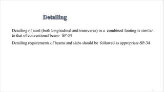
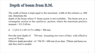
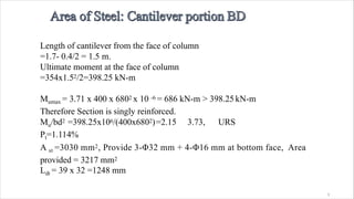
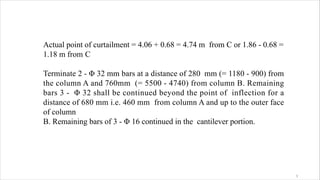
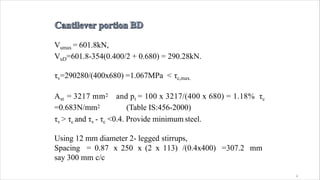
![Area provided =1000 x 314 / 130 = 2415 mm2
22
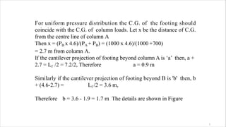
Mu/bd2 =3.07 3.73, URS
Mu=0.87 fy Ast[d-fyAst/(fckb)]
pt=1.7%
Ast = 2380 mm2
Use Φ20 mm diameter bar at spacing= 1000 x 314 / 2380
= 131.93 say 130 mm c/c](https://image.slidesharecdn.com/footingdesign-200402170424/85/Footing-design-22-320.jpg)
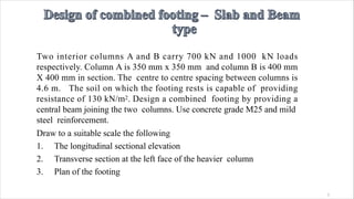
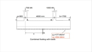
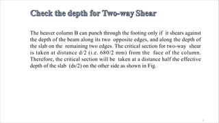
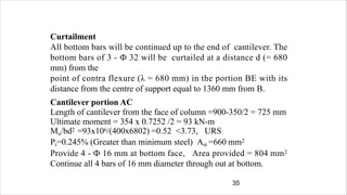
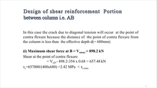
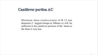
![Ldt= [0.87 x 250 / (4 x 1.4)]Ф =39 Ф
= 39 x 20 = 780 mm
Available length of bar=825 - 25 = 800mm
> 780 mm and hence safe.
Transverse reinforcement
Required Ast=0.15bD/100
=0.15x1000 x 200/100 = 300mm2
Using Ф8 mm bars, Spacing=1000x50/300
= 160 mm
Provide distribution steel of Ф8 mm at 160 mm
c/c,<300, <5d
2](https://image.slidesharecdn.com/footingdesign-200402170424/85/Footing-design-24-320.jpg)
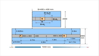
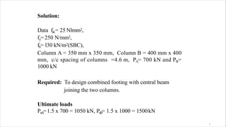
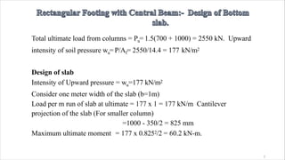
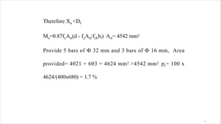
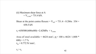
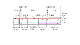
![The beam acts as an isolated T- beam. bf = [Lo/( Lo / b +4)]+ bw, where,
Lo = 4.6 - 0.206 - 0.68 = 3.714 m = 3714 mm
b= actual width of flange = 2000 mm, b w = 400mm
bf = [3714/(3714/2000+4) + 400] =1034mm <2000mm
Df =200 mm, Mu= 628 kN-m
Moment of resistance Muf of a beam for x u =Dfis : Muf= [0.36 x 25 x1034
x 200(680 - 0.42x200)]x10-6
= 1109 kN.m > Mu ( = 628 kN-m)
3](https://image.slidesharecdn.com/footingdesign-200402170424/85/Footing-design-34-320.jpg)
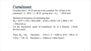
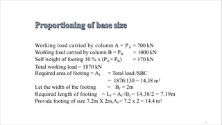
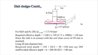
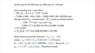
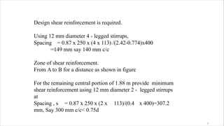
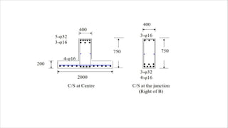
![Area of steel available 3 - Φ 16 + 3 - Φ 32 ,
Ast = 3016 mm2
pt = 100 x 3016 / (400 x 680) = 1.1% τc=0.664MPa
τv > τc
Design shear reinforcement is required. Using 12 mm diameter 4
- legged stirrups,
Spacing= [0.87 x 250x(4x113)] /(2.42-0.664)x400 =139 mm
say 120 mm c/c
Zone of shear reinforcements between τv to τc
= m from support B towards A
3](https://image.slidesharecdn.com/footingdesign-200402170424/85/Footing-design-39-320.jpg)
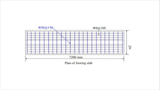


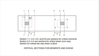
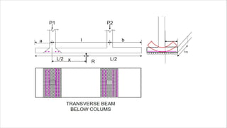
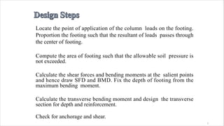
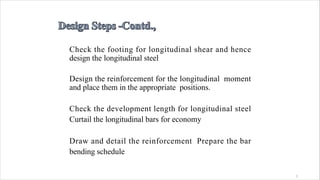
- The document discusses the design of a combined footing to support two columns carrying loads of 700 kN and 1000 kN respectively. - A trapezoidal combined footing of size 7.2m x 2m is designed to support the loads and transmit them uniformly to the soil. - Longitudinal and transverse reinforcement is designed for the footing and a central beam is included to join the two columns. Detailed design calculations and drawings of the footing and beam are presented.


