John Beumer III DDS, MS
Robert F. Faulkner, DDS
Kumar C. Shah DDS, MS
Division of Advanced Prosthodontics, UCLA
Restora(on	
  of	
  posterior	
  quadrants	
  
Pa(ent	
  selec(on,	
  and	
  treatment	
  planning	
  
This	
  program	
  of	
  instruc(on	
  is	
  protected	
  by	
  copyright	
  ©.	
  	
  No	
  por(on	
  of	
  this	
  
program	
  of	
  instruc(on	
  may	
  be	
  reproduced,	
  recorded	
  or	
  transferred	
  by	
  any	
  means	
  
electronic,	
  digital,	
  photographic,	
  mechanical	
  etc.,	
  or	
  by	
  any	
  informa(on	
  storage	
  or	
  
retrieval	
  system,	
  without	
  prior	
  permission.	
  
Table of Contents
Treatment options
–  RPD’s
–  Fixed dental prostheses
–  Endodontic therapy
Implant biomechanics
–  Number of implants per unit
–  Staggered vs. linear configurations
–  Length, implant diameter
–  Cantilevers
–  Occlusal factors
–  Parafunctional activity
–  Strategies to avoid biomechanical related problems
Anatomic limitations and the role of preprosthetic surgery
–  Grafting
–  Distraction osteogenesis
–  Socket augmentation and ridge preservation
–  Placement of implants into fresh extraction sites
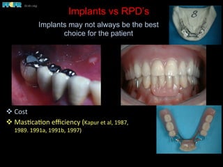
Implants vs RPD’s
v Cost	
  
v Mas(ca(on	
  efficiency	
  (Kapur	
  et	
  al,	
  1987,	
  
1989.	
  1991a,	
  1991b,	
  1997)	
  	
  
Implants may not always be the best
choice for the patient
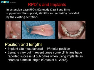
RPD’s and Implants
Position and lengths
•  Implant site most favored – 1st molar position
•  Lengths vary but in recent times some clinicians have
reported successful outcomes when using implants as
short as 6 mm in length (Gates et al, 2012).
In	
  extension	
  base	
  RPD’s	
  (Kennedy	
  Class	
  I	
  and	
  II)	
  to	
  
supplement	
  the	
  support,	
  stability	
  and	
  reten(on	
  provided	
  
by	
  the	
  exis(ng	
  den((on.	


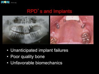
RPD’s and Implants
•  Unanticipated implant failures
•  Poor quality bone
•  Unfavorable biomechanics
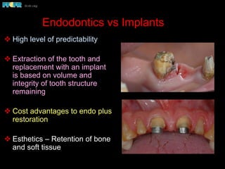
Endodontics vs Implants
v High level of predictability
v Extraction of the tooth and
replacement with an implant
is based on volume and
integrity of tooth structure
remaining
v Cost advantages to endo plus
restoration
v Esthetics – Retention of bone
and soft tissue
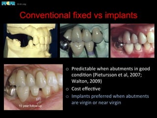
Conventional fixed vs implants
o  Predictable	
  when	
  abutments	
  in	
  good	
  
condi(on	
  (Pietursson	
  et	
  al,	
  2007;	
  
Walton,	
  2009)	
  
o  Cost	
  effec(ve	
  
o  Implants	
  preferred	
  when	
  abutments	
  
are	
  virgin	
  or	
  near	
  virgin	


15 year follow-up
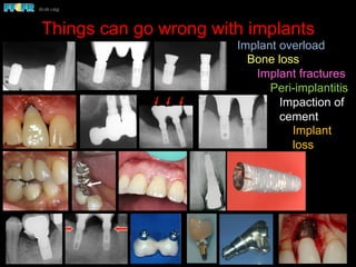
Things can go wrong with implants
Biomechanics – Partially Edentulous Patients
!  Because of the curve of Spee and the distal angulation of the implants, the
occlusal loads (arrow) are nonaxial.
!  Note the bone loss around the implants. Linear configurations in the posterior
region, such as in this patient, are particularly vulnerable to the effects of
nonaxial loading, particularly brachycephalic individuals.
Nonaxial loads and implant overload in posterior
quadrants
Semi-precision attachments
usion of the natural tooth abutment
ears after delivery the patient noticed the premolar
o intrude. Exam revealed that the screw retaining the
ad become loose, hence the rotation of this crown.
Bruxism - Case Report
This is a five year followup x-ray of
a patient with an implant
supported fixed partial denture.
Closer exam revealed
both implants to be
fractured .
The patient was a heavy bruxer.
Six months later he presented
with significant bone loss around
both implants.
Bruxism - Case Report
This is a five year followup x-ray of
a patient with an implant
supported fixed partial denture.
The patient was a heavy bruxer.
Six months later he presented
with significant bone loss around
both implants.
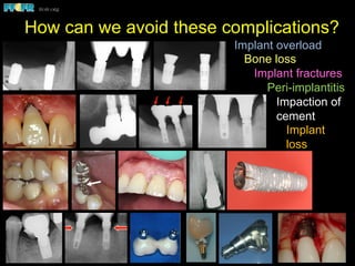
Implant overload
Bone loss
Implant fractures
Peri-implantitis
Impaction of
cement
Implant
loss
How can we avoid these complications?
Biomechanics – Partially Edentulous Patients
!  Because of the curve of Spee and the distal angulation of the implants, the
occlusal loads (arrow) are nonaxial.
!  Note the bone loss around the implants. Linear configurations in the posterior
region, such as in this patient, are particularly vulnerable to the effects of
nonaxial loading, particularly brachycephalic individuals.
Nonaxial loads and implant overload in posterior
quadrants
Semi-precision attachments
usion of the natural tooth abutment
ears after delivery the patient noticed the premolar
o intrude. Exam revealed that the screw retaining the
ad become loose, hence the rotation of this crown.
Bruxism - Case Report
This is a five year followup x-ray of
a patient with an implant
supported fixed partial denture.
Closer exam revealed
both implants to be
fractured .
The patient was a heavy bruxer.
Six months later he presented
with significant bone loss around
both implants.
Bruxism - Case Report
This is a five year followup x-ray of
a patient with an implant
supported fixed partial denture.
The patient was a heavy bruxer.
Six months later he presented
with significant bone loss around
both implants.
Implant overload
Bone loss
Implant fractures
Peri-implantitis
Impaction of
cement
Implant
loss
Implant Biomechanics and
Treatment Planning
Why should we be concerned with
implant biomechanics when we develop
a plan of treatment?
Because if we are not, we risk implant
overload and prosthesis failures such
as fracture and screw loosening.
Implant overload can lead to bone loss around
implants and eventually implant failure.
Bone	
  is	
  a	
  dynamic	
  structure.	
  	
  Excessive	
  loads	
  lead	
  to	
  
a	
  resorp(ve	
  remodeling	
  response	
  
  Hoshaw et al (1994) observed a resorptive remodeling of the
bone around implants subjected to excessive axial loads (300N).
Bone loss was observed at the crest around the neck of the
implant and in the zone of bone adjacent to the body of the
implant
  Brunski et al, 2000
  Recent studies by Myata et al (1998, 2000, 2008) and Nagasawa
et al, (2013) have reconfirmed Hoshaw and Brunski’s original
hypothesis
Is it possible to overload the bone anchoring an
osseointegrated implant?
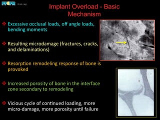
Implant Overload - Basic
Mechanism
v Excessive	
  occlusal	
  loads,	
  off	
  angle	
  loads,	
  
bending	
  moments	
  
v Resul(ng	
  microdamage	
  (fractures,	
  cracks,	
  
and	
  delamina(ons)	
  
v Resorp(on	
  remodeling	
  response	
  of	
  bone	
  is	
  
provoked	
  
v Increased	
  porosity	
  of	
  bone	
  in	
  the	
  interface	
  
zone	
  secondary	
  to	
  remodeling	
  
v Vicious	
  cycle	
  of	
  con(nued	
  loading,	
  more	
  
micro-­‐damage,	
  more	
  porosity	
  un(l	
  failure	
  
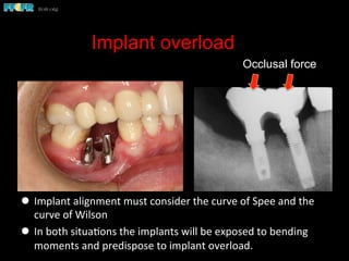
Implant overload
l  Implant	
  alignment	
  must	
  consider	
  the	
  curve	
  of	
  Spee	
  and	
  the	
  
curve	
  of	
  Wilson	
  
l  In	
  both	
  situa(ons	
  the	
  implants	
  will	
  be	
  exposed	
  to	
  bending	
  
moments	
  and	
  predispose	
  to	
  implant	
  overload.	
  
Occlusal force
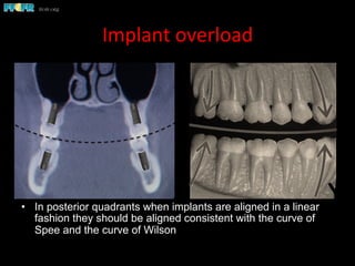
Implant	
  overload	
  
•  In posterior quadrants when implants are aligned in a linear
fashion they should be aligned consistent with the curve of
Spee and the curve of Wilson
Curve of Wilson
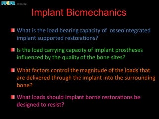
Implant Biomechanics
	
  
  What	
  is	
  the	
  load	
  bearing	
  capacity	
  of	
  	
  osseointegrated	
  
implant	
  supported	
  restora(ons?	


  Is	
  the	
  load	
  carrying	
  capacity	
  of	
  implant	
  prostheses	
  
influenced	
  by	
  the	
  quality	
  of	
  the	
  bone	
  sites?	


  What	
  factors	
  control	
  the	
  magnitude	
  of	
  the	
  loads	
  that	
  
are	
  delivered	
  through	
  the	
  implant	
  into	
  the	
  surrounding	
  
bone?	
  
  What	
  loads	
  should	
  implant	
  borne	
  restora(ons	
  be	
  
designed	
  to	
  resist?	


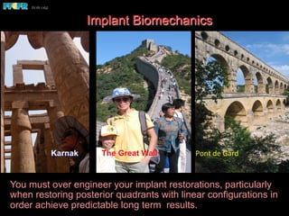
Karnak The Great Wall Pont	
  de	
  Gard	
  
You must over engineer your implant restorations, particularly
when restoring posterior quadrants with linear configurations in
order achieve predictable long term results.
Implant Biomechanics
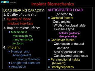
Implant	
  Biomechanics	
  
LOAD BEARING CAPACITY
1.	
  Quality	
  of	
  bone	
  site	


2.	
  Quality	
  of	
  	
  bone	


  implant	
  interface	
  
3.	
  Implant	
  microsurfaces	


  Machined	
  vs	
  
	
  microrough	
  	
  vs	
  
	
  nano-­‐enhanced	
  
	
  surfaces	
  
4. Implant
 Number and
Arrangement
Linear vs Curvilinear
 Length and diameter
 Angulation
ANTICIPATED LOAD
(Affected by)
 Occlusal factors
Cusp angles
Width of occlusal table
Guidance type
Anterior guidance
Group function
 Cantilever forces
Connection to natural
dentition
Size of occlusal table
Cantilevered prostheses
 Parafunctional habits
(bruxism)
 Brachycephalics
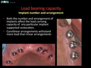
Load	
  bearing	
  capacity	
  
Implant	
  number	
  and	
  arrangement	
  
•  Both	
  the	
  number	
  and	
  arrangement	
  of	
  
implants	
  affect	
  the	
  load	
  carrying	
  
capacity	
  of	
  	
  any	
  par(cular	
  implant	
  
supported	
  restora(on.	


•  Curvilinear	
  arrangements	
  withstand	
  
more	
  load	
  than	
  linear	
  arrangements	
  
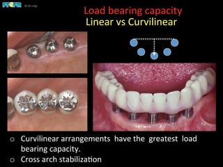
Load	
  bearing	
  capacity	


  Linear	
  vs	
  Curvilinear	
  
o  Curvilinear	
  arrangements	
  	
  have	
  the	
  	
  greatest	
  	
  load	
  
bearing	
  capacity.	
  
o  Cross	
  arch	
  stabiliza(on	
  
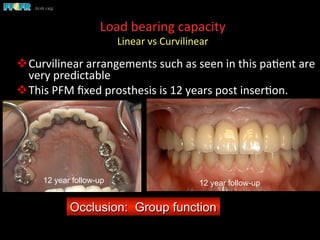
Load	
  bearing	
  capacity	
  
Linear	
  vs	
  Curvilinear	


v Curvilinear	
  arrangements	
  such	
  as	
  seen	
  in	
  this	
  pa(ent	
  are	
  
very	
  predictable	
  
v This	
  PFM	
  fixed	
  prosthesis	
  is	
  12	
  years	
  post	
  inser(on.	
  
Occlusion: Group function
12 year follow-up12 year follow-up
Load	
  bearing	
  capacity	
  
Linear	
  vs	
  Curvilinear	
  
	
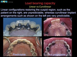
  Linear configurations restoring the cuspid region, such as the
patient on the right, are unpredictable, whereas curvilinear implant
arrangements such as shown on the left are very predictable.
Predictable Not predictable
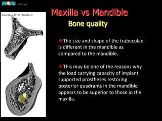
Maxilla vs Mandible
Bone quality
v The	
  size	
  and	
  shape	
  of	
  the	
  trabeculae	
  
is	
  different	
  in	
  the	
  mandible	
  as	
  
compared	
  to	
  the	
  mandible.	


v This	
  may	
  be	
  one	
  of	
  the	
  reasons	
  why	
  
the	
  load	
  carrying	
  capacity	
  of	
  implant	
  
supported	
  prostheses	
  restoring	
  
posterior	
  quadrants	
  in	
  the	
  mandible	
  
appears	
  to	
  be	
  superior	
  to	
  those	
  in	
  the	
  
maxilla.	
  
Courtesy	
  Dr.	
  C.	
  Stanford	
  
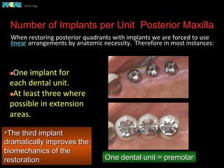
Number of Implants per Unit Posterior Maxilla
	
  When	
  restoring	
  posterior	
  quadrants	
  with	
  implants	
  we	
  are	
  forced	
  to	
  use	
  
linear	
  arrangements	
  by	
  anatomic	
  necessity.	
  	
  Therefore	
  in	
  most	
  instances:	


*The third implant
dramatically improves the
biomechanics of the
restoration
 One	
  implant	
  for	
  
each	
  dental	
  unit.	
  
 At	
  least	
  three	
  where	
  
possible	
  in	
  extension	
  
areas.	
  
One dental unit = premolar
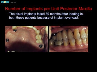
Number of Implants per Unit Posterior Maxilla
The distal implants failed 30 months after loading in
both these patients because of implant overload.
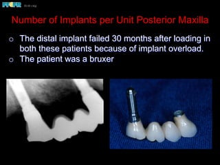
Number of Implants per Unit Posterior Maxilla
o  The distal implant failed 30 months after loading in
both these patients because of implant overload.
o  The patient was a bruxer
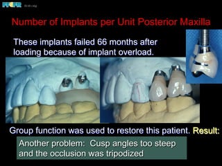
Number of Implants per Unit Posterior Maxilla
These implants failed 66 months after
loading because of implant overload.
Group function was used to restore this patient. Result:
 Application of excessive lateral forces
 Implant failure
Another problem: Cusp angles too steep
and the occlusion was tripodized
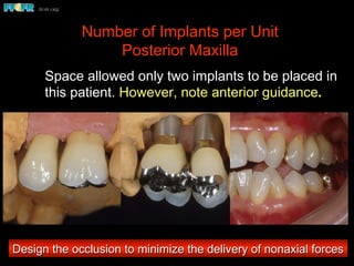
Number of Implants per Unit
Posterior Maxilla
Space allowed only two implants to be placed in
this patient. However, note anterior guidance.
Design the occlusion to minimize the delivery of nonaxial forces
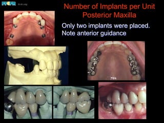
Number of Implants per Unit
Posterior Maxilla
Only two implants were placed.
Note anterior guidance
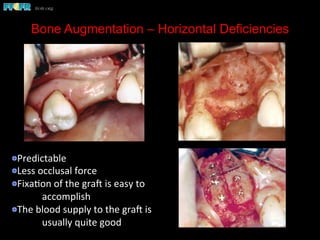
Bone Augmentation – Horizontal Deficiencies
 Predictable	
  
 Less	
  occlusal	
  force	
  
 Fixa(on	
  of	
  the	
  grae	
  is	
  easy	
  to	
  
	
  accomplish	
  
 The	
  blood	
  supply	
  to	
  the	
  grae	
  is	
  
	
  usually	
  quite	
  good	


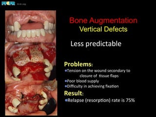
Bone Augmentation
Vertical Defects
Less	
  predictable	
  
Problems:	
  
 Tension	
  on	
  the	
  wound	
  secondary	
  to	
  
	
  closure	
  of	
  	
  (ssue	
  flaps	
  
 Poor	
  blood	
  supply	
  
 Difficulty	
  in	
  achieving	
  fixa(on	
  
Result:	
  
 Relapse	
  (resorp(on)	
  rate	
  is	
  75%	
  
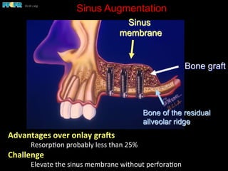
Sinus Augmentation
Advantages	
  over	
  onlay	
  gra7s	
  
	
  Resorp(on	
  probably	
  less	
  than	
  25%	
  
Challenge	
  
	
  Elevate	
  the	
  sinus	
  membrane	
  without	
  perfora(on	
  
Sinus
membrane
Bone graft
Bone of the residual
allveolar ridge
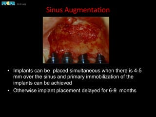
Sinus	
  Augmenta(on	
  
•  Implants can be placed simultaneous when there is 4-5
mm over the sinus and primary immobilization of the
implants can be achieved
•  Otherwise implant placement delayed for 6-9 months
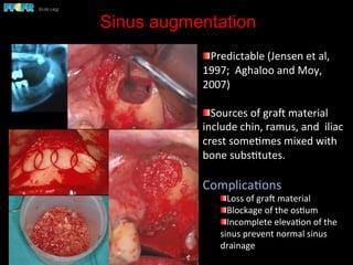
Sinus augmentation


 Predictable	
  (Jensen	
  et	
  al,	
  
1997;	
  	
  Aghaloo	
  and	
  Moy,	
  
2007)	
  	
  
 Sources	
  of	
  grae	
  material	
  
include	
  chin,	
  ramus,	
  and	
  	
  iliac	
  
crest	
  some(mes	
  mixed	
  with	
  
bone	
  subs(tutes.	
  
Complica(ons	
  
 Loss	
  of	
  grae	
  material	
  
 Blockage	
  of	
  the	
  os(um	
  
 Incomplete	
  eleva(on	
  of	
  the	
  
sinus	
  prevent	
  normal	
  sinus	
  
drainage	
  
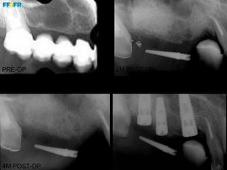
PRE-OP
4M POST-OP
2M POST-OP
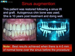
Sinus augmention
This patient was restored following a sinus lift
and graft. Autogenous chin bone was used.
She is 10 years post treatment and doing well.
Note: Best results achieved when there is 4-5 mm
of normal bone over the sinus before the procedure
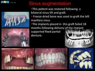
Sinus augmentation
§ This	
  pa(ent	
  was	
  restored	
  following	
  	
  a	


bilateral	
  sinus	
  lie	
  and	
  grae.	
  	
  
§ 	
  Freeze	
  dried	
  bone	
  was	
  used	
  to	
  grae	
  the	
  lee	
  
maxillary	
  sinus.	


§ The	
  implants	
  placed	
  in	
  	
  this	
  grae	
  failed	
  18	
  
months	
  following	
  delivery	
  of	
  the	
  implant	
  
supported	
  fixed	
  par(al	
  	
  
denture.	
  
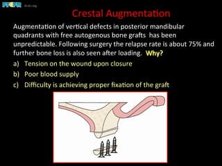
Crestal	
  Augmenta(on	
  
Augmenta(on	
  of	
  ver(cal	
  defects	
  in	
  posterior	
  mandibular	
  
quadrants	
  with	
  free	
  autogenous	
  bone	
  graes	
  	
  has	
  been	
  
unpredictable.	
  Following	
  surgery	
  the	
  relapse	
  rate	
  is	
  about	
  75%	
  and	
  
further	
  bone	
  loss	
  is	
  also	
  seen	
  aeer	
  loading.	
  	
  Why?	
  
a)  Tension	
  on	
  the	
  wound	
  upon	
  closure	
  
b)  Poor	
  blood	
  supply	
  	
  
c)  Difficulty	
  is	
  achieving	
  proper	
  fixa(on	
  of	
  the	
  grae	
  	
  
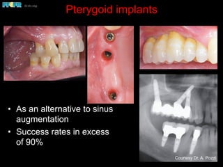
Pterygoid implants
•  As an alternative to sinus
augmentation
•  Success rates in excess
of 90%
Courtesy Dr. A. Pozzi
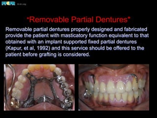
*Removable Partial Dentures*
Removable partial dentures properly designed and fabricated
provide the patient with masticatory function equivalent to that
obtained with an implant supported fixed partial dentures
(Kapur, et al, 1992) and this service should be offered to the
patient before grafting is considered.
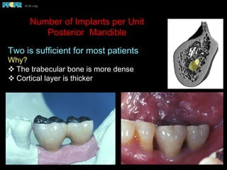
Number of Implants per Unit
Posterior Mandible
Two is sufficient for most patients
Why?
v The trabecular bone is more dense
v Cortical layer is thicker
Number of Implants per Unit
Posterior Mandible
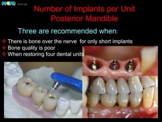
v There is bone over the nerve for only short implants
v Bone quality is poor
v When restoring four dental units
Three are recommended when:
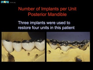
Number of Implants per Unit
Posterior Mandible
Three implants were used to
restore four units in this patient
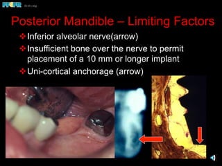
Posterior Mandible – Limiting Factors
v Inferior alveolar nerve(arrow)
v Insufficient bone over the nerve to permit
placement of a 10 mm or longer implant
v Uni-cortical anchorage (arrow)
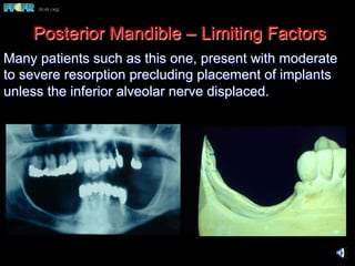
Many patients such as this one, present with moderate
to severe resorption precluding placement of implants
unless the inferior alveolar nerve displaced.
Posterior Mandible – Limiting Factors
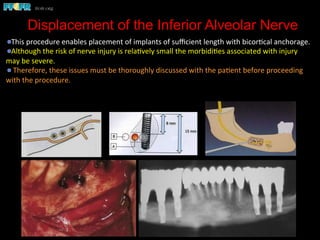
Displacement of the Inferior Alveolar Nerve
 This	
  procedure	
  enables	
  placement	
  of	
  implants	
  of	
  sufficient	
  length	
  with	
  bicor(cal	
  anchorage.	
  	
  
 Although	
  the	
  risk	
  of	
  nerve	
  injury	
  is	
  rela(vely	
  small	
  the	
  morbidi(es	
  associated	
  with	
  injury	
  
may	
  be	
  severe.	


  Therefore,	
  these	
  issues	
  must	
  be	
  thoroughly	
  discussed	
  with	
  the	
  pa(ent	
  before	
  proceeding	
  
with	
  the	
  procedure.	
  
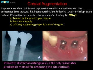
Crestal Augmentation
Augmenta(on	
  of	
  ver(cal	
  defects	
  in	
  posterior	
  mandibular	
  quadrants	
  with	
  free	
  
autogenous	
  bone	
  graes	
  (A)	
  has	
  been	
  unpredictable.	
  Following	
  surgery	
  the	
  relapse	
  rate	
  
is	
  about	
  75%	
  and	
  further	
  bone	
  loss	
  is	
  also	
  seen	
  aeer	
  loading	
  (B).	
  	
  Why?	
  
	
  a)	
  Tension	
  on	
  the	
  wound	
  upon	
  closure	
  
	
  b)	
  Poor	
  blood	
  supply	


  c)	
  Difficulty	
  is	
  achieving	
  proper	
  fixa(on	
  of	
  the	
  grae	
  	
  
BA
Presently,	
  distrac(on	
  osteogenesis	
  is	
  the	
  only	
  reasonably	
  
predictable	
  method	
  for	
  enhancing	
  this	
  site	
  ver(cally.	
  	
  
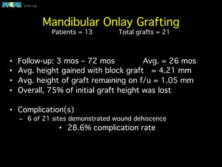
Mandibular Onlay Grafting

Patients = 13 Total grafts = 21
•  Follow-up: 3 mos – 72 mos Avg. = 26 mos
•  Avg. height gained with block graft = 4.21 mm
•  Avg. height of graft remaining on f/u = 1.05 mm
•  Overall, 75% of initial graft height was lost
•  Complication(s)
–  6 of 21 sites demonstrated wound dehiscence
•  28.6% complication rate
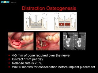
Distraction Osteogenesis
§  4-5 mm of bone required over the nerve
§  Distract 1mm per day
§  Relapse rate is 25 %
§  Wait 6 months for consolidation before implant placement
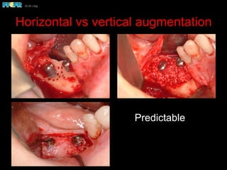
Horizontal vs vertical augmentation
Predictable
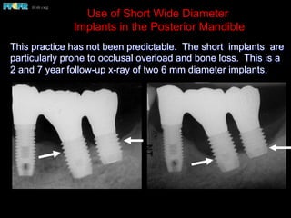
Use of Short Wide Diameter
Implants in the Posterior Mandible
This practice has not been predictable. The short implants are
particularly prone to occlusal overload and bone loss. This is a
2 and 7 year follow-up x-ray of two 6 mm diameter implants.
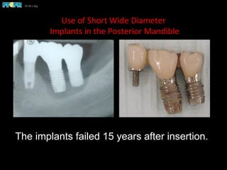
Use	
  of	
  Short	
  Wide	
  Diameter	
  
	
  Implants	
  in	
  the	
  Posterior	
  Mandible	
  
The implants failed 15 years after insertion.
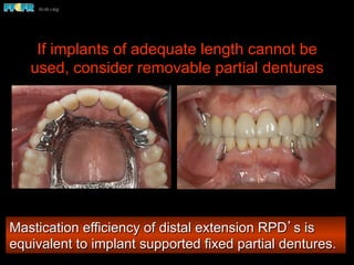
If implants of adequate length cannot be
used, consider removable partial dentures
Mastication efficiency of distal extension RPD’s is
equivalent to implant supported fixed partial dentures.
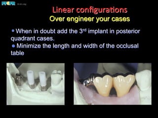
 When in doubt add the 3rd implant in posterior
quadrant cases.
 Minimize the length and width of the occlusal
table
Linear	
  configura(ons
Over engineer your cases
Over-engineer your linear quadrant cases
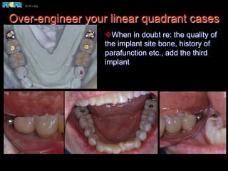
v When in doubt re: the quality of
the implant site bone, history of
parafunction etc., add the third
implant
Over-engineer your linear quadrant cases
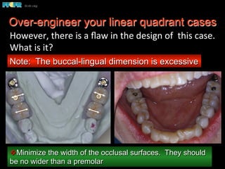
v Minimize the width of the occlusal surfaces. They should
be no wider than a premolar
Note: The buccal-lingual dimension is excessive
However,	
  there	
  is	
  a	
  flaw	
  in	
  the	
  design	
  of	
  	
  this	
  case.	
  	
  
What	
  is	
  it?	
  
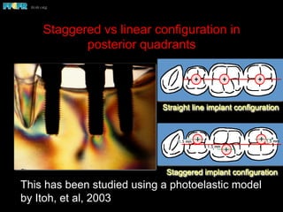
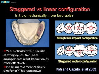
Staggered vs linear configuration in
posterior quadrants
This has been studied using a photoelastic model
by Itoh, et al, 2003
Staggered implant configuration
1.5 mm
1.5 mm 1.5 mm
Straight line implant configuration
Staggered vs linear configuration
Staggered implant configuration
1.5 mm
1.5 mm 1.5 mm
Straight line implant configuration
Itoh and Caputo, et al 2003
Is	
  it	
  biomechanically	
  more	
  favorable?	


v Yes,	
  par(cularly	
  with	
  specific	
  
chewing	
  cycles.	
  Nonlinear	
  
arrangements	
  resist	
  lateral	
  forces	
  
more	
  effec(vely	
  
v Is	
  the	
  improvement	
  clinically	
  
significant?	
  This	
  is	
  unknown	
  
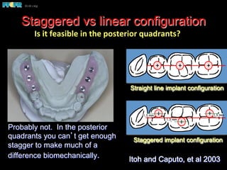
Staggered vs linear configuration
Staggered implant configuration
1.5 mm
1.5 mm 1.5 mm
Straight line implant configuration
Probably not. In the posterior
quadrants you can’t get enough
stagger to make much of a
difference biomechanically. Itoh and Caputo, et al 2003
Is	
  it	
  feasible	
  in	
  the	
  posterior	
  quadrants?	
  
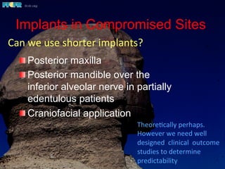
Implants in Compromised Sites
 Posterior maxilla
 Posterior mandible over the
inferior alveolar nerve in partially
edentulous patients
 Craniofacial application
Theore(cally	
  perhaps.	


However	
  we	
  need	
  well	
  
designed	
  	
  clinical	
  	
  outcome	
  
studies	
  to	
  determine	
  
predictability	
  
Can	
  we	
  use	
  shorter	
  implants?	
  
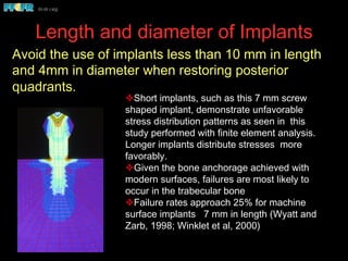
Length and diameter of Implants
v Short implants, such as this 7 mm screw
shaped implant, demonstrate unfavorable
stress distribution patterns as seen in this
study performed with finite element analysis.
Longer implants distribute stresses more
favorably.
v Given the bone anchorage achieved with
modern surfaces, failures are most likely to
occur in the trabecular bone
v Failure rates approach 25% for machine
surface implants 7 mm in length (Wyatt and
Zarb, 1998; Winklet et al, 2000)
Avoid the use of implants less than 10 mm in length
and 4mm in diameter when restoring posterior
quadrants.
Cho et al, 1993
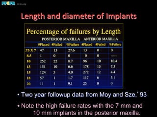
• Two year followup data from Moy and Sze,’93
• Note the high failure rates with the 7 mm and
10 mm implants in the posterior maxilla.
Length	
  and	
  diameter	
  of	
  Implants	
  
Implant length vs diameter
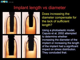
Using a photoelastic model,
Caputo et al, 2002 attempted
to determine whether
increasing the diameter of the
implant or increasing the length
of the implant had a significant
impact on stress distribution.
They concluded that:
Does increasing the
diameter compensate for
the lack of sufficient
length?
Implant length vs diameter
Lingual
load
Axial
load
Buccal
load
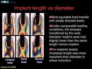
 Most equitable load transfer
with axially directed loads.
 Under comparable loading
conditions, the stresses
transferred by the wide
diameter implant were only
slightly lower than the same
length narrow implant.
 For implants tested,
increased length was more
important than diameter in
stress reduction.
Caputo	
  et	
  al,2002	
  
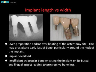
Implant length vs width
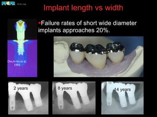
§ Failure rates of short wide diameter
implants approaches 20%.
2 years 8 years
Cho,In	
  Ho	
  et	
  al,	
  
1992	
  
14 years
Implant	
  length	
  vs	
  width	
  
l  Over-­‐prepara(on	
  and/or	
  over	
  hea(ng	
  of	
  the	
  osteotomy	
  site.	
  	
  This	
  
may	
  precipitate	
  early	
  loss	
  of	
  bone,	
  par(cularly	
  around	
  the	
  neck	
  of	
  
the	
  implant.	
  	
  
l  Implant	
  overload.	
  
l  Insufficient	
  trabecular	
  bone	
  encasing	
  the	
  implant	
  on	
  its	
  buccal	
  
and	
  lingual	
  aspect	
  leading	
  to	
  progressive	
  bone	
  loss.	


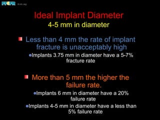
Ideal Implant Diameter
4-5 mm in diameter
Less than 4 mm the rate of implant
fracture is unacceptably high
Implants 3.75 mm in diameter have a 5-7%
fracture rate
More than 5 mm the higher the
failure rate.
Implants 6 mm in diameter have a 20%
failure rate
Implants 4-5 mm in diameter have a less than
5% failure rate
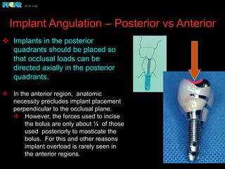
Implant Angulation – Posterior vs Anterior
v  Implants in the posterior
quadrants should be placed so
that occlusal loads can be
directed axially in the posterior
quadrants.
v  In the anterior region, anatomic
necessity precludes implant placement
perpendicular to the occlusal plane.
v  However, the forces used to incise
the bolus are only about ¼ of those
used posteriorly to masticate the
bolus. For this and other reasons
implant overload is rarely seen in
the anterior regions.
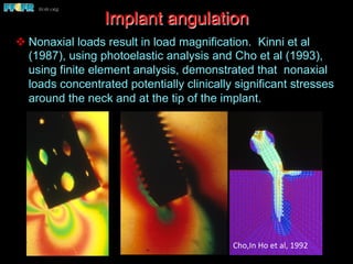
v Nonaxial loads result in load magnification. Kinni et al
(1987), using photoelastic analysis and Cho et al (1993),
using finite element analysis, demonstrated that nonaxial
loads concentrated potentially clinically significant stresses
around the neck and at the tip of the implant.
Implant angulation
Cho,In	
  Ho	
  et	
  al,	
  1992	
  
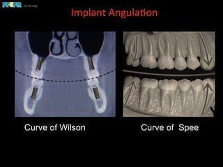
Curve of Wilson
Implant	
  Angula(on	
  	
  
Curve of Wilson Curve of Spee
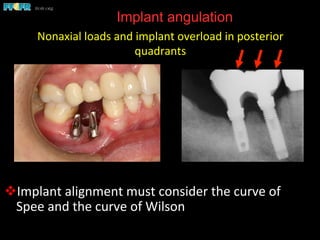
Implant angulation
v Implant	
  alignment	
  must	
  consider	
  the	
  curve	
  of	
  
Spee	
  and	
  the	
  curve	
  of	
  Wilson	
  
Nonaxial	
  loads	
  and	
  implant	
  overload	
  in	
  posterior	
  
quadrants	
  
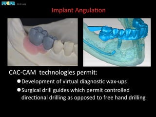
Implant	
  Angula(on	
  	
  
CAC-­‐CAM	
  	
  technologies	
  permit:	
  
l Development	
  of	
  virtual	
  diagnos(c	
  wax-­‐ups	
  
l Surgical	
  drill	
  guides	
  which	
  permit	
  controlled	
  
direc(onal	
  drilling	
  as	
  opposed	
  to	
  free	
  hand	
  drilling	
  
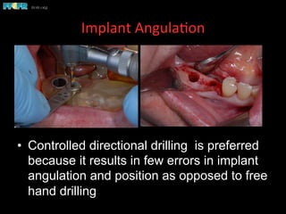
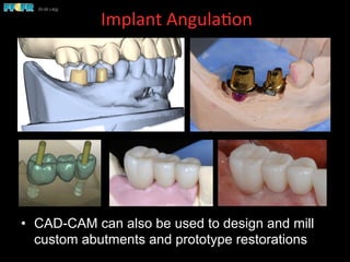
Implant	
  Angula(on	
  	
  
•  Controlled directional drilling is preferred
because it results in few errors in implant
angulation and position as opposed to free
hand drilling
Implant	
  Angula(on	
  	
  
•  CAD-CAM can also be used to design and mill
custom abutments and prototype restorations
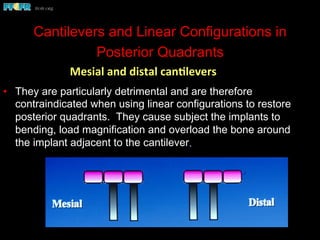
Cantilevers and Linear Configurations in
Posterior Quadrants
•  They are particularly detrimental and are therefore
contraindicated when using linear configurations to restore
posterior quadrants. They cause subject the implants to
bending, load magnification and overload the bone around
the implant adjacent to the cantilever.
Mesial	
  and	
  distal	
  canClevers	
  
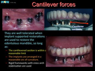
 They	
  are	
  well	
  tolerated	
  when	
  
implant	
  supported	
  restora(ons	
  
are	
  used	
  to	
  restore	
  the	
  
edentulous	
  mandible,	
  so	
  long	
  
as:	
  
–  The	
  can(levered	
  sec(on	
  is	
  within	
  a	
  
reasonable	
  limit	
  
–  The	
  implants	
  are	
  arranged	
  in	
  a	
  
reasonable	
  arc	
  of	
  curvature.	
  
–  Rigid	
  frameworks	
  with	
  cross	
  arch	
  
stabiliza(on	
  are	
  used	
  
Cantilever forces
Cantilever
section
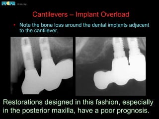
Cantilevers – Implant Overload
•  Note the bone loss around the dental implants adjacent
to the cantilever.
Restorations designed in this fashion, especially
in the posterior maxilla, have a poor prognosis.
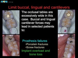
Limit buccal, lingual and cantilevers
The occlusal tables are
excessively wide in this
case. Buccal and lingual
cantilever forces may
lead in selected patients
to:
Prosthesis failures
• Porcelain fractures
• Screw fractures
Implant overload and
bone loss
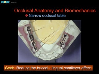
Occlusal Anatomy and Biomechanics
v Narrow occlusal table
Goal: Reduce the buccal - lingual cantilever effect
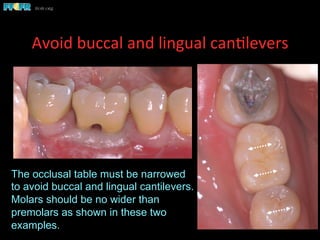
Avoid	
  buccal	
  and	
  lingual	
  can(levers	
  	
  
The occlusal table must be narrowed
to avoid buccal and lingual cantilevers.
Molars should be no wider than
premolars as shown in these two
examples.
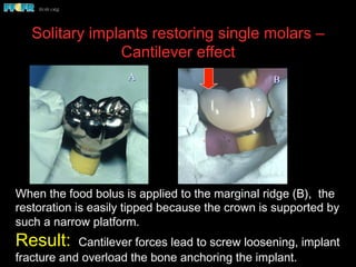
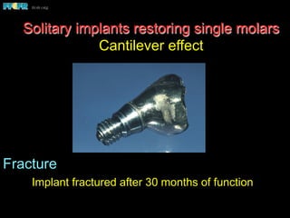
Solitary implants restoring single molars –
Cantilever effect
When the food bolus is applied to the marginal ridge (B), the
restoration is easily tipped because the crown is supported by
such a narrow platform.
Result: Cantilever forces lead to screw loosening, implant
fracture and overload the bone anchoring the implant.
BA
Fracture
Implant fractured after 30 months of function
Solitary implants restoring single molars
Cantilever effect
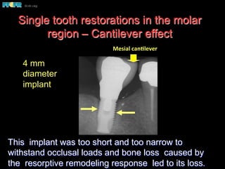
Single tooth restorations in the molar
region – Cantilever effect
This implant was too short and too narrow to
withstand occlusal loads and bone loss caused by
the resorptive remodeling response led to its loss.
4 mm
diameter
implant
Mesial	
  canClever	
  
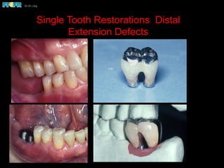
Single Tooth Restorations Distal
Extension Defects
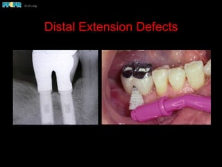
Distal Extension Defects
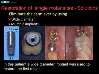
Restoration of single molar sites - Solutions
In this patient a wide diameter implant was used to
restore the first molar.
	
  Eliminate	
  the	
  can(lever	
  by	
  using	
  
 	
  Wide	
  diameter	
  
 	
  Mul(ple	
  implants	
  
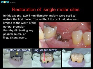
Restoration of single molar sites
Custom abutment Lingual set screw
In	
  this	
  pa(ent,	
  	
  two	
  4	
  mm	
  diameter	
  implant	
  were	
  used	
  to	
  
restore	
  the	
  first	
  molar.	
  	
  The	
  width	
  of	
  the	
  occlusal	
  table	
  was	
  
limited	
  to	
  the	
  width	
  of	
  the	
  
natural	
  premolar,	
  	
  
thereby	
  elimina(ng	
  any	
  
possible	
  buccal	
  or	
  	
  
lingual	
  can(levers.	
  
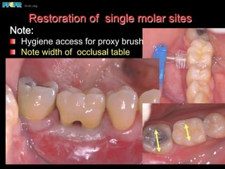
Restoration of single molar sites
Note:
  Hygiene access for proxy brush
  Note width of occlusal table
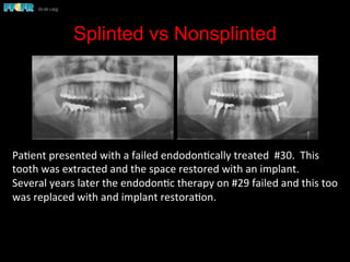
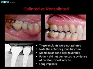
Splinted vs Nonsplinted
Pa(ent	
  presented	
  with	
  a	
  failed	
  endodon(cally	
  treated	
  	
  #30.	
  	
  This	
  
tooth	
  was	
  extracted	
  and	
  the	
  space	
  restored	
  with	
  an	
  implant.	
  	
  
Several	
  years	
  later	
  the	
  endodon(c	
  therapy	
  on	
  #29	
  failed	
  and	
  this	
  too	
  
was	
  replaced	
  with	
  and	
  implant	
  restora(on.	


Splinted	
  vs	
  Nonsplinted	
  
•  These	
  implants	
  were	
  not	
  splinted	
  
•  Note	
  the	
  anterior	
  group	
  func(on	
  
•  Mandibular	
  bone	
  sites	
  favorable	
  
•  Pa(ent	
  did	
  not	
  demonstrate	
  evidence	
  
of	
  parafunc(onal	
  ac(vity	
  
•  Long	
  implants	
  
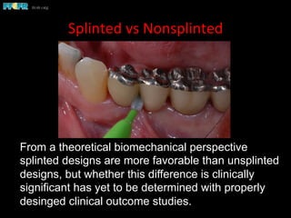
Splinted	
  vs	
  Nonsplinted	
  
From a theoretical biomechanical perspective
splinted designs are more favorable than unsplinted
designs, but whether this difference is clinically
significant has yet to be determined with properly
desinged clinical outcome studies.
Criteria for splinting
•  If the patient shows signs of parafunctional activities.
•  If the quality of bone anchoring the implants is questionable (type
IV bone, or if the implants are in grafted sites).
•  Misangled implants ie, implants that are not perpindicular to the
plane of occlusion.
•  If relatively short implants have been employed (less than 10 mm
in length).
•  If the patient presents with or is to be restored with group
function. Linear configurations of implants lack cross arch
stabilization and are less able to resist bending moments
(nonaxial loads) and implant angulations that are not ideal result
in the application of bending moments.
•  All maxillary posterior quadrant cases.
l When	
  implants	
  of	
  10	
  in	
  length	
  or	
  longer	
  are	
  placed.	
  
l When	
  the	
  	
  quality	
  of	
  bone	
  is	
  good.	
  	
  
l Implants	
  placed	
  with	
  perfect	
  angula(on	
  	
  
(perpendicular	
  to	
  the	
  plane	
  of	
  occlusion)	
  
l Absence	
  of	
  parafunc(onal	
  ac(vity.	
  
Nonsplinted	
  designs	
  are	
  used	
  when	
  restoring	
  posterior	
  
quadrants	
  only	
  in	
  the	
  mandible	
  and	
  under	
  the	
  following	
  
circumstances:	
  
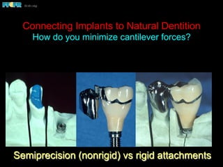
Connecting Implants to Natural Dentition
How do you minimize cantilever forces?
Semiprecision (nonrigid) vs rigid attachments
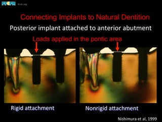
Connecting Implants to Natural Dentition
Posterior	
  implant	
  apached	
  to	
  anterior	
  abutment	
  
Rigid	
  apachment	


Nonrigid	
  apachment	
  
Nishimura	
  et	
  al,	
  1999	
  
Loads applied in the pontic area
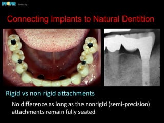
Connecting Implants to Natural Dentition
Rigid	
  vs	
  non	
  rigid	
  apachments	
  
	
  No	
  difference	
  as	
  long	
  as	
  the	
  nonrigid	
  (semi-­‐precision)	
  
apachments	
  remain	
  fully	
  seated	
  	
  
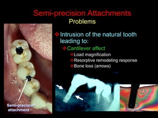
Semi-precision Attachments
Problems
v Intrusion of the natural tooth
leading to:
v Cantilever affect
v Load magnification
v Resorptive remodeling response
v Bone loss (arrows)
Semi-precision
attachment
Semi-precision attachments
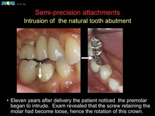
Intrusion of the natural tooth abutment
•  Eleven years after delivery the patient noticed the premolar
began to intrude. Exam revealed that the screw retaining the
molar had become loose, hence the rotation of this crown.
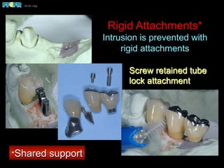
Rigid Attachments*
Intrusion is prevented with
rigid attachments
Screw retained tube
lock attachment
*Shared support
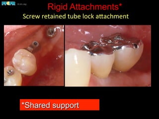
Rigid Attachments*
Screw	
  retained	
  tube	
  lock	
  apachment	
  
*Shared support
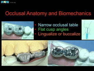
Occlusal Anatomy and Biomechanics
•  Narrow occlusal table
•  Flat cusp angles
•  Lingualize or buccalize