Downloaded 2,339 times
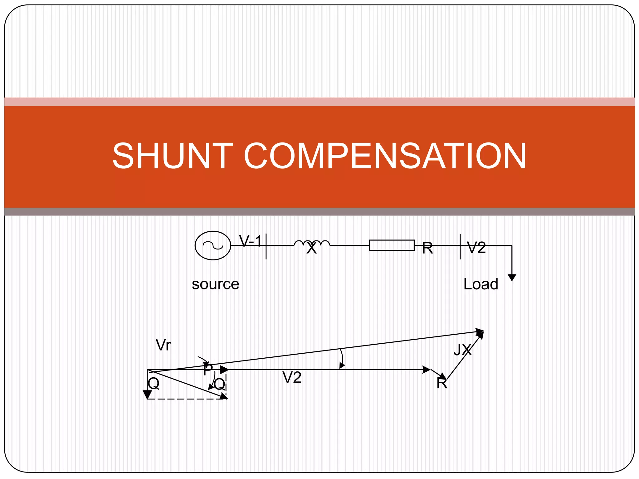
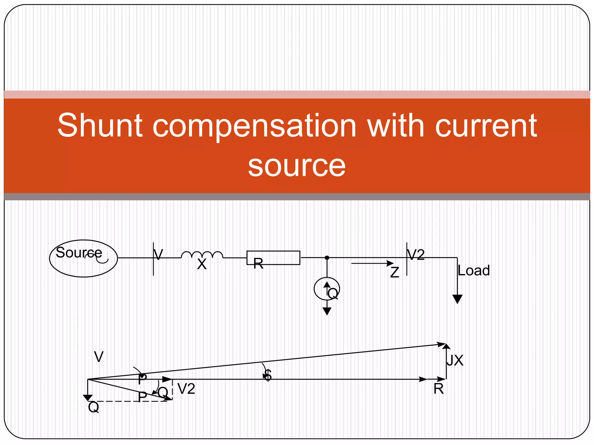
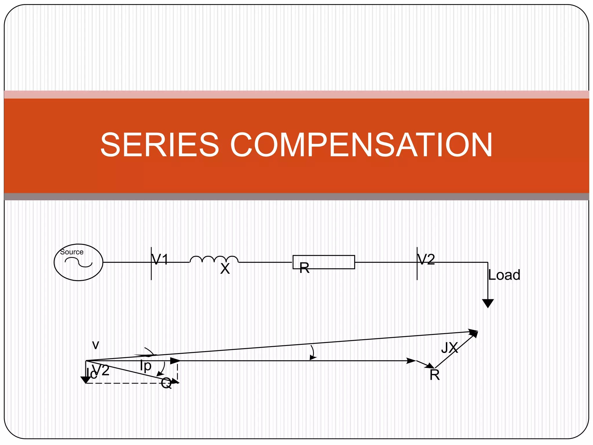
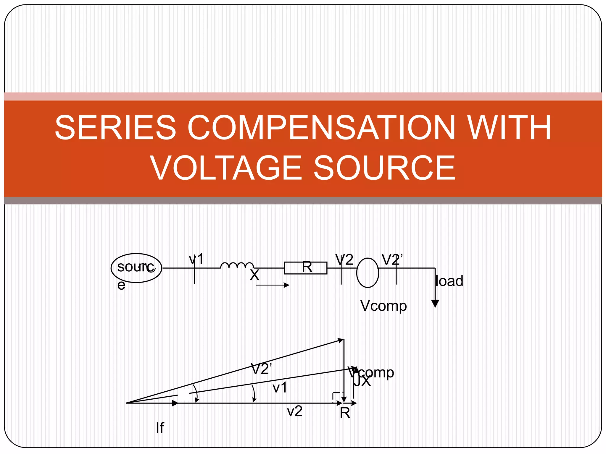
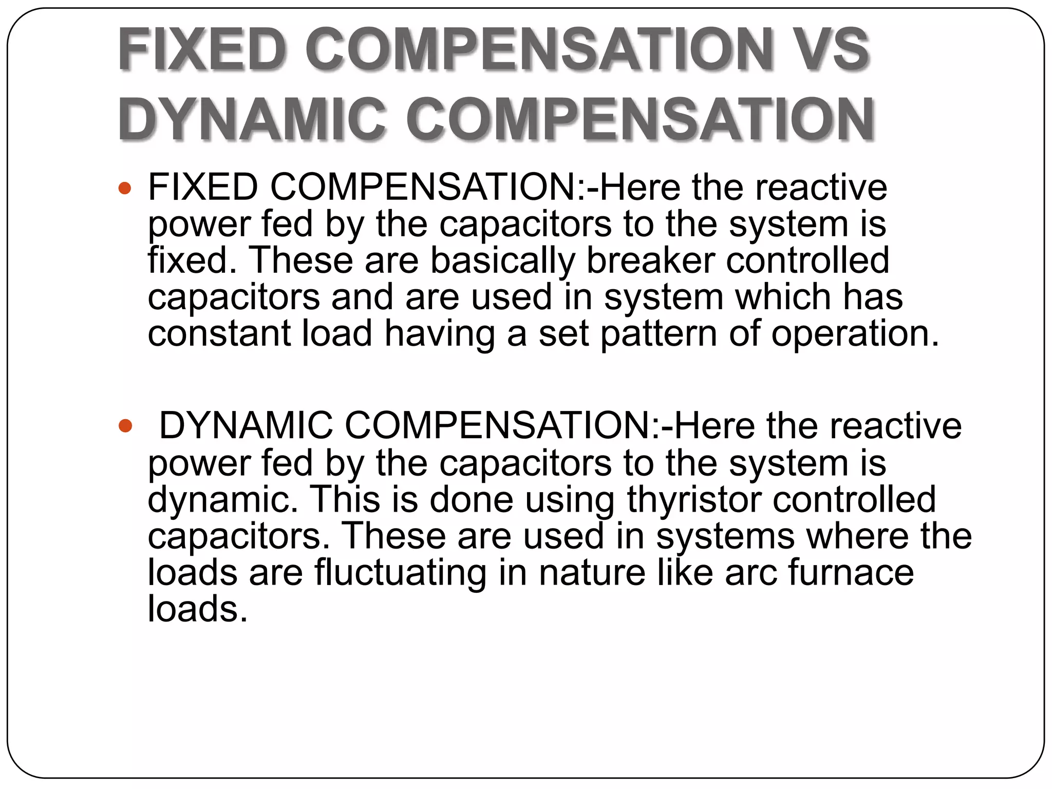
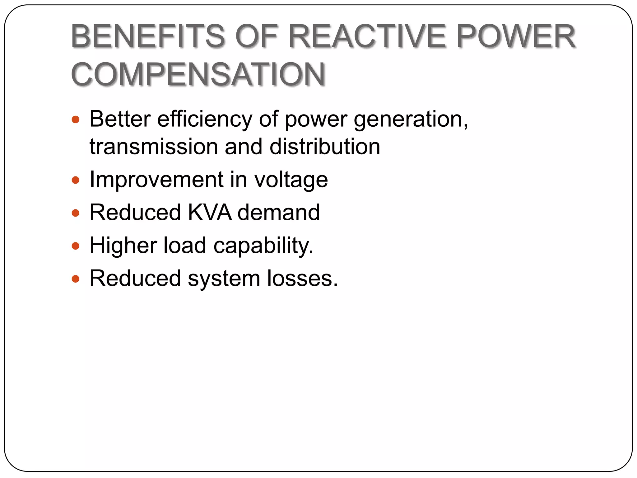

This document provides an overview of reactive power compensation. It defines reactive power compensation as any device connected in series or parallel with a load to supply the reactive power demanded. There are two main types of compensation: shunt compensation using parallel capacitors to improve power factor and boost voltage, and series compensation using series capacitors to boost receiving end voltage and transmission capacity. Fixed compensation uses breaker controlled capacitors for constant loads, while dynamic compensation uses thyristor controlled capacitors for fluctuating loads. Benefits include better efficiency, improved voltage, reduced losses and higher load capability. Capacitors are used as they generate reactive power to supply loads.