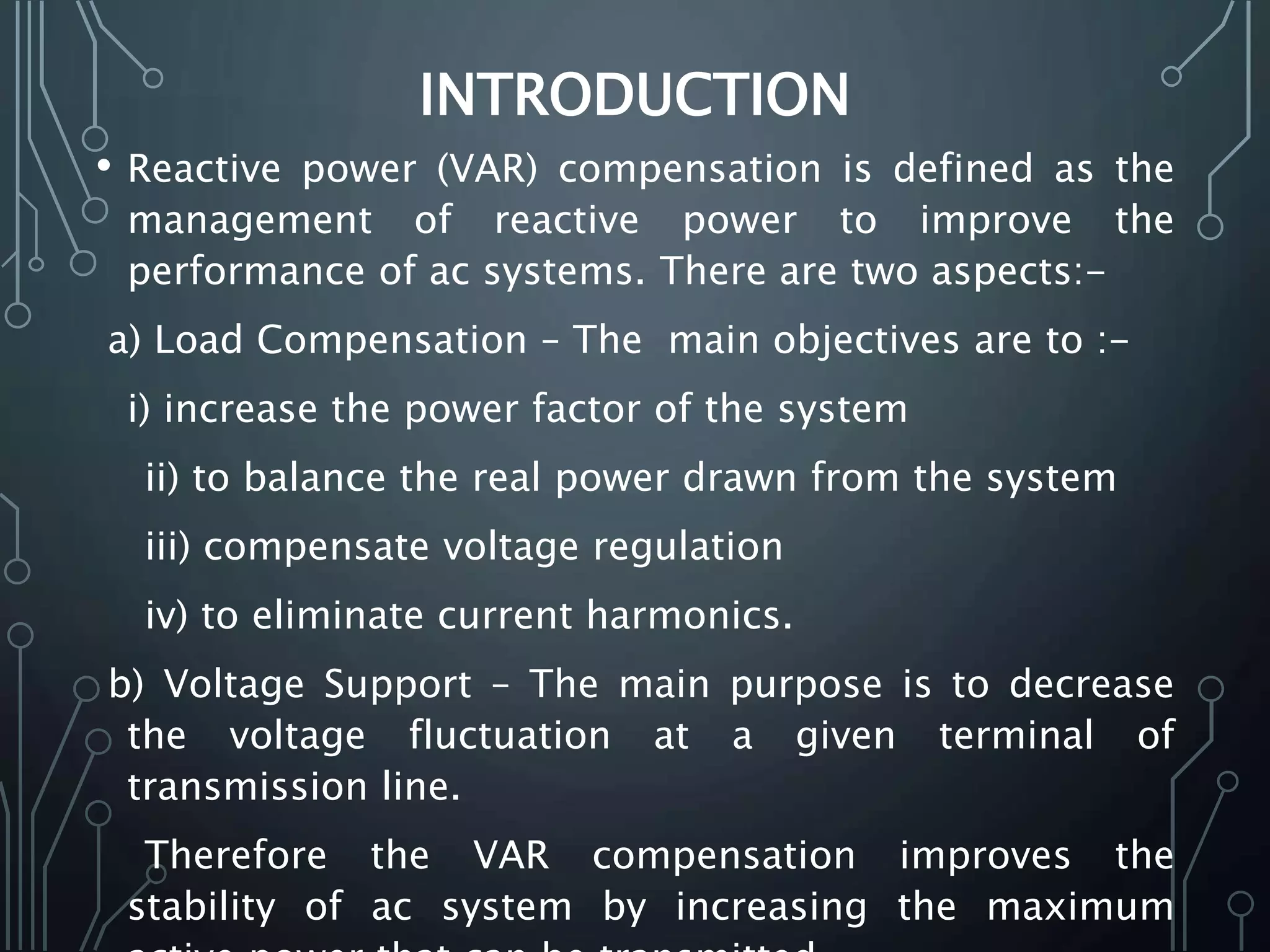
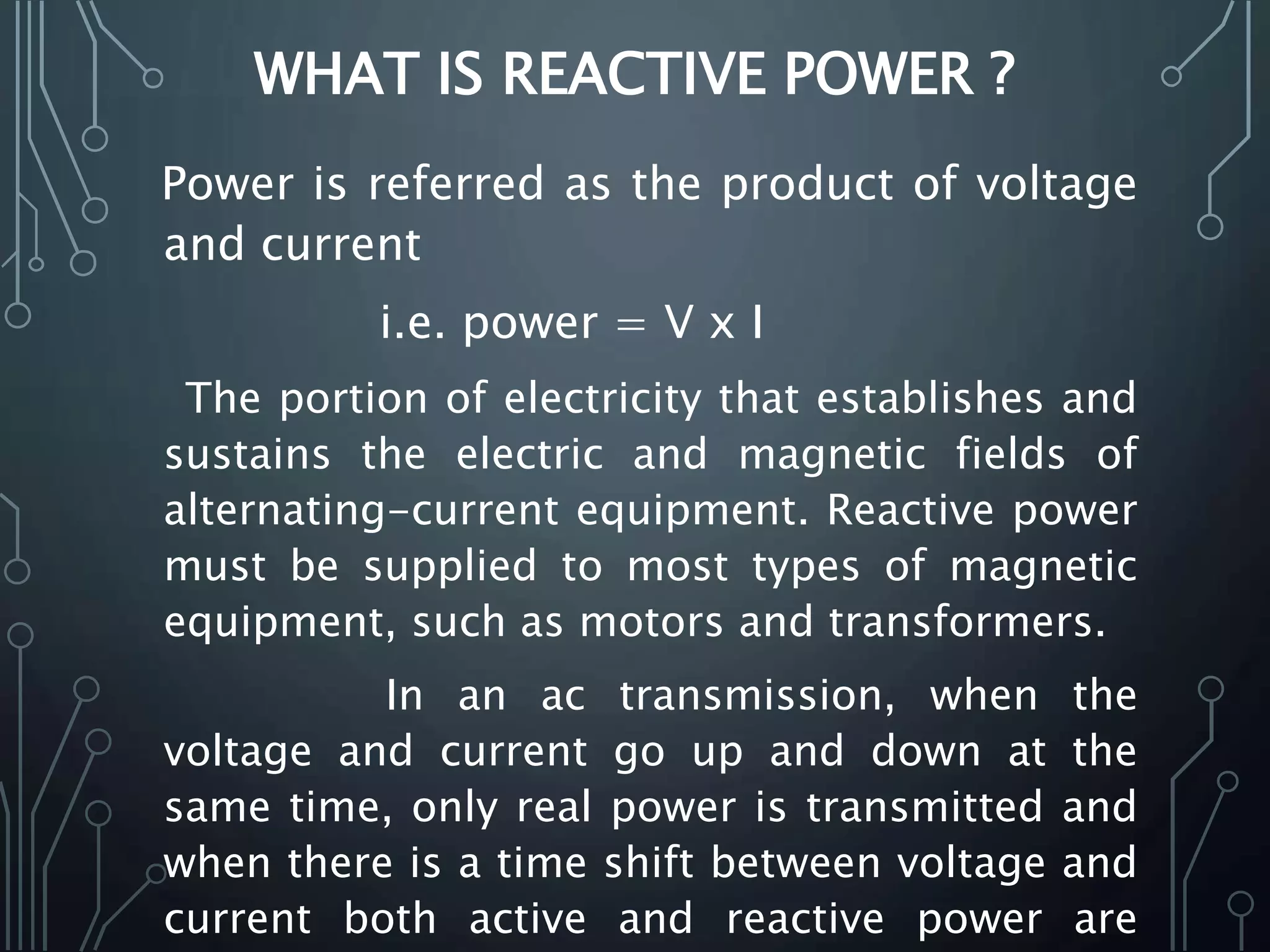
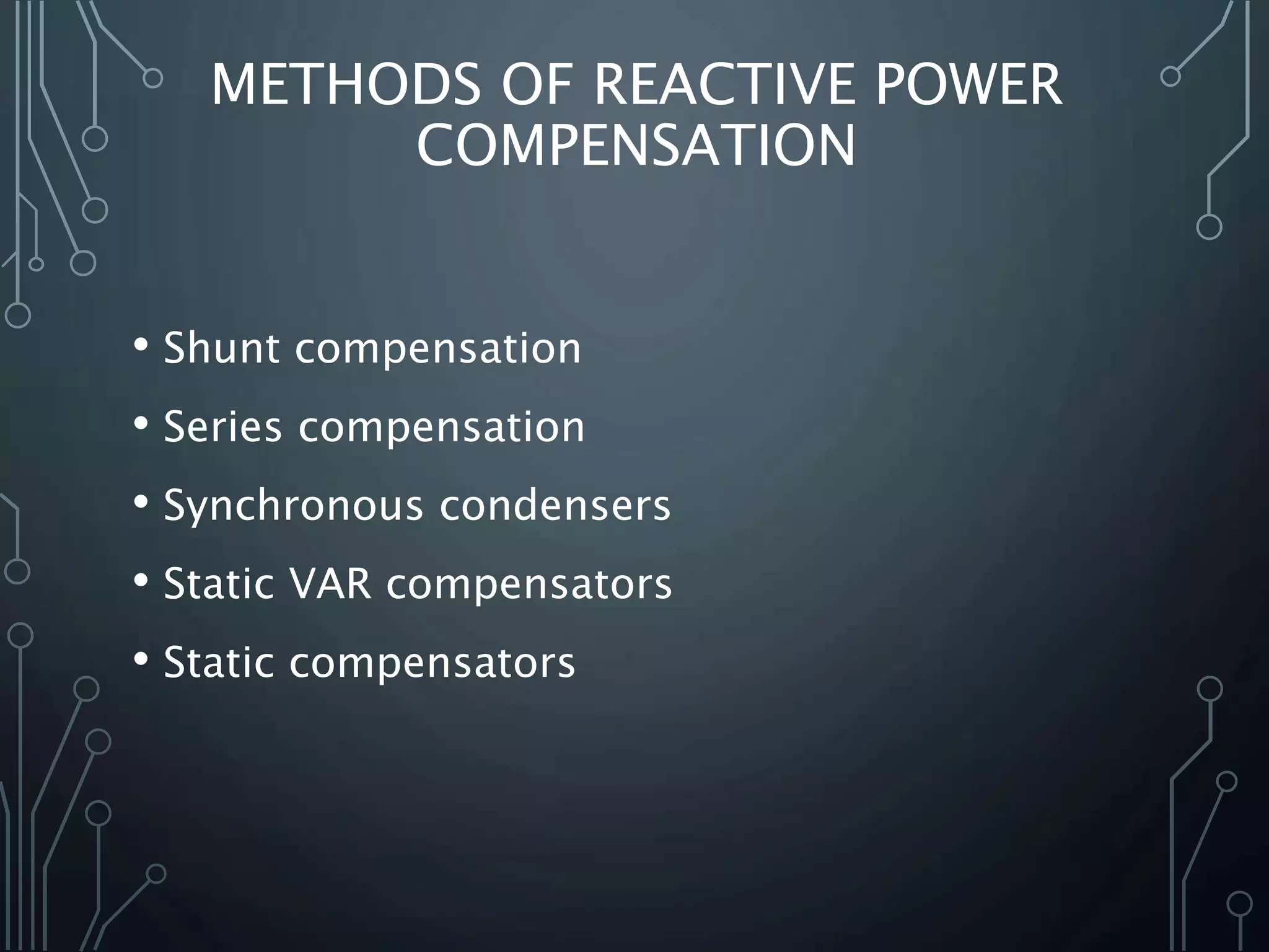
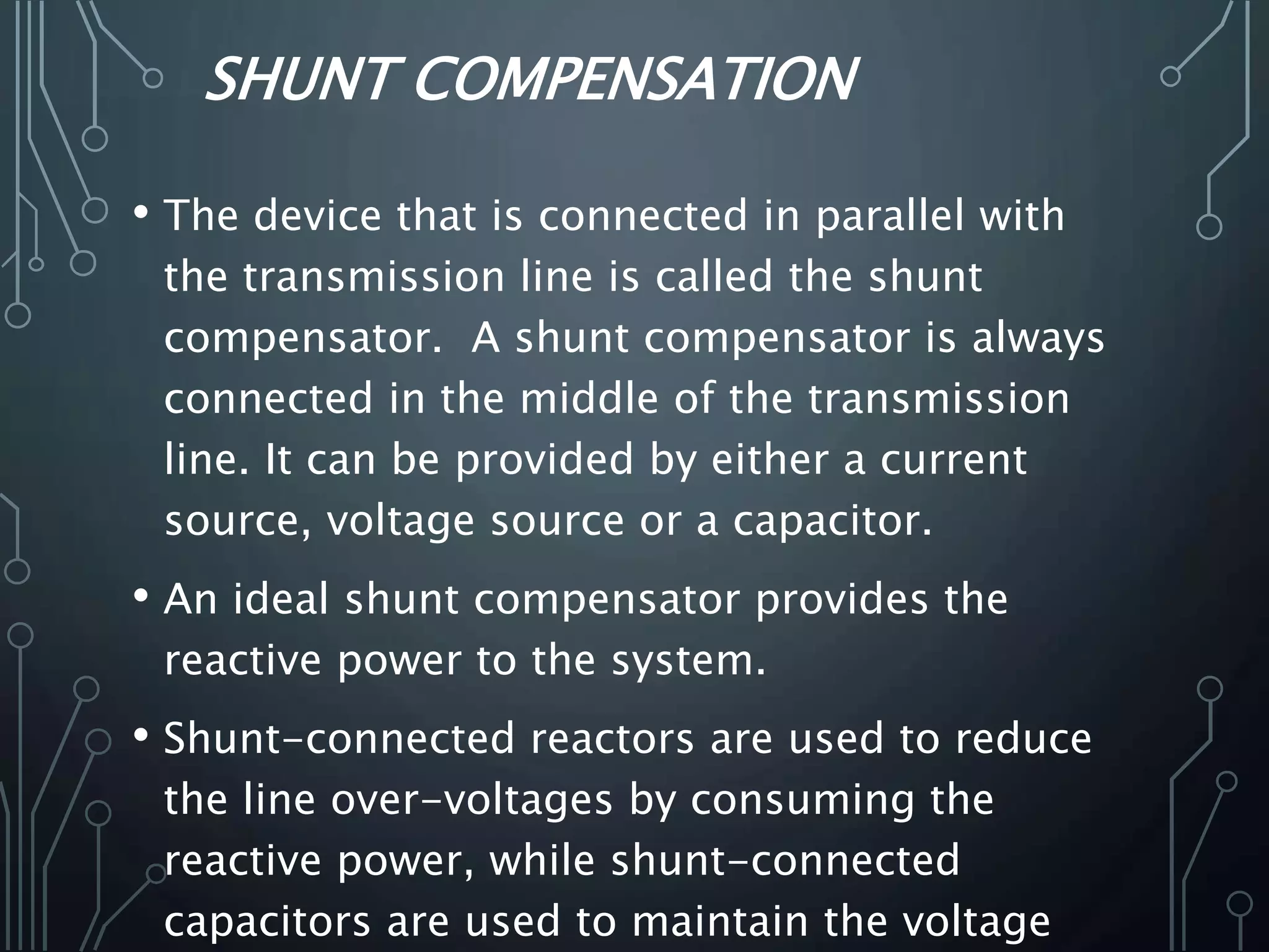
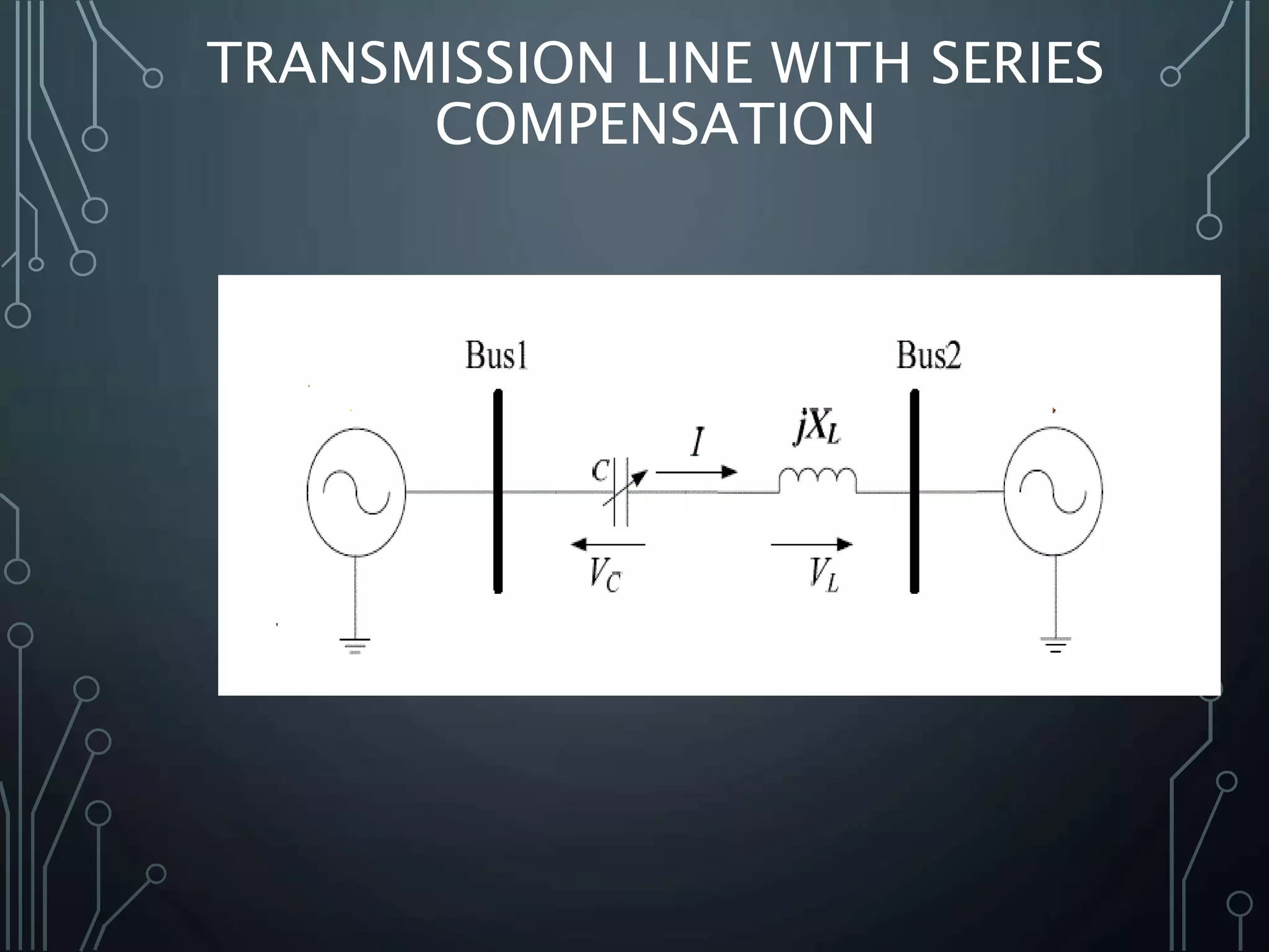
A PRESENTATION ON
REACTIVE POWER
COMPENSATION
BY
I.REVANTH
13911A0218
EEE-A
CONTENTS
• Introduction
• Reactive power
• Need for reactive power
• Need for reactive power compensation
• Shunt compensation
• Series compensation
• Static VAR compensators (SVC)
• Static compensators (STATCOM)
• Synchronous Condensor
• Conclusion
• References
INTRODUCTION
• Reactive power (VAR) compensation is defined as the
management of reactive power to improve the
performance of ac systems. There are two aspects:-
a) Load Compensation – The main objectives are to :-
i) increase the power factor of the system
ii) to balance the real power drawn from the system
iii) compensate voltage regulation
iv) to eliminate current harmonics.
b) Voltage Support – The main purpose is to decrease
the voltage fluctuation at a given terminal of
transmission line.
Therefore the VAR compensation improves the
stability of ac system by increasing the maximum
WHAT IS REACTIVE POWER ?
Power is referred as the product of voltage
and current
i.e. power = V x I
The portion of electricity that establishes and
sustains the electric and magnetic fields of
alternating-current equipment. Reactive power
must be supplied to most types of magnetic
equipment, such as motors and transformers.
In an ac transmission, when the
voltage and current go up and down at the
same time, only real power is transmitted and
when there is a time shift between voltage and
current both active and reactive power are
POWER TRIANGLE
• Power factor = cosø
= real power / apparent power
= kW/ kVA
Whenever there is a phase shift
between V and I we have:-
a) real power (kW)
b) reactive (imaginary ) power (kVAR)
c) The combination is a complex or
apparent power (kVA)=√(kW)² + (kVAR)²www.8051.in
WHY DO WE NEED REACTIVE POWER?
• In resistive loads the current produces the heat
energy which produces the desired output but
incase of inductive loads the current creates
the magnetic field which further produces the
desired work. Therefore reactive power is the
non working power caused by the magnetic
current to operate and sustain magnetism in
the device .
• Reactive power (vars) is required to maintain
the voltage to deliver active power
(watts)through transmission lines. When there
is not enough reactive power the voltage sags
NEED FOR REACTIVE POWER
COMPENSATION
• Reactive power generated by the ac power
source is stored in a capacitor or a reactor
during a quarter of a cycle and in the next
quarter of the cycle it is sent back to the power
source. Therefore the reactive power oscillates
between the ac source and the capacitor or
reactor at a frequency equals to two times the
rated value (50 or 60 Hz). So to avoid the
circulation between the load and source it
needs to be compensated .
• Also to regulate the power factor of the system
and maintain the voltage stability we need to
METHODS OF REACTIVE POWER
COMPENSATION
• Shunt compensation
• Series compensation
• Synchronous condensers
• Static VAR compensators
• Static compensators
SHUNT COMPENSATION
• The device that is connected in parallel with
the transmission line is called the shunt
compensator. A shunt compensator is always
connected in the middle of the transmission
line. It can be provided by either a current
source, voltage source or a capacitor.
• An ideal shunt compensator provides the
reactive power to the system.
• Shunt-connected reactors are used to reduce
the line over-voltages by consuming the
reactive power, while shunt-connected
capacitors are used to maintain the voltage
TRANSMISSION LINE WITH SHUNT
COMPENSATION
SERIES COMPENSATION
• When a device is connected in series with the
transmission line it is called a series
compensator. A series compensator can be
connected anywhere in the line.
• There are two modes of operation – capacitive
mode of operation and inductive mode of
operation.
• A simplified model of a transmission system
with series compensation is shown in Figure
.The voltage magnitudes of the two buses are
TRANSMISSION LINE WITH SERIES
COMPENSATION
STATIC VAR COMPENSATORS
• A static VAR compensator (or SVC) is an electrical device
for providing reactive power on
transmission networks. The term "static" refers to the
fact that the SVC has no moving parts (other than circuit
breakers and disconnects, which do not move under
normal SVC operation).
• The SVC is an automated impedance matching device,
designed to bring the system closer to unity power
factor. If the power system's reactive load
is capacitive(leading), the SVC will use reactors (usually
in the form of thyristor-Controlled Reactors) to
consume vars from the system, lowering the system
voltage.
www.8051.in
STATIC COMPENSATOR
• The devices use synchronous voltage sources
for generating or absorbing reactive power. A
synchronous voltage source (SVS) is
constructed using a voltage source converter
(VSC). Such a shunt compensating device is
called static compensator or STATCOM .
• A STATCOM usually contains an SVS that is
driven from a dc storage capacitor and the SVS
is connected to the ac system bus through an
interface transformer. The transformer steps
the ac system voltage down such that the
STRUCTURE OF STATCOM
• Basically, the
STATCOM system is
comprised of
• Power converters,
• Set of coupling
reactors or a step-up
transformer,
• Controller
SYNCHRONOUS CONDENSOR
• A device whose main function is the
improvement of pf of the electrical system is
known as the synchronous condensor. It is
installed at the receiving end of the line .
• When a synchronous condensor is introduced
it supplies the kVAR to the system , and hence
the current is reduced .
• Therefore the losses are reduced and provides
a better efficiency . Hence more power can be
delivered to the load and improves the pf of
the system.
www.8051.in
CONCLUSION
• From all the previous discussion we can
conclude reactive power compensation
is a must for improving the
performance of the ac system. By
reactive power compensation we can
control the power factor and reduce the
consumption of electricity.
www.8051.in
THANK YOU!!

Reactivepowercompensation 140401183847-phpapp01 (6)

  • 1.
    A PRESENTATION ON REACTIVEPOWER COMPENSATION BY I.REVANTH 13911A0218 EEE-A
  • 2.
    CONTENTS • Introduction • Reactivepower • Need for reactive power • Need for reactive power compensation • Shunt compensation • Series compensation • Static VAR compensators (SVC) • Static compensators (STATCOM) • Synchronous Condensor • Conclusion • References
  • 3.
    INTRODUCTION • Reactive power(VAR) compensation is defined as the management of reactive power to improve the performance of ac systems. There are two aspects:- a) Load Compensation – The main objectives are to :- i) increase the power factor of the system ii) to balance the real power drawn from the system iii) compensate voltage regulation iv) to eliminate current harmonics. b) Voltage Support – The main purpose is to decrease the voltage fluctuation at a given terminal of transmission line. Therefore the VAR compensation improves the stability of ac system by increasing the maximum
  • 4.
    WHAT IS REACTIVEPOWER ? Power is referred as the product of voltage and current i.e. power = V x I The portion of electricity that establishes and sustains the electric and magnetic fields of alternating-current equipment. Reactive power must be supplied to most types of magnetic equipment, such as motors and transformers. In an ac transmission, when the voltage and current go up and down at the same time, only real power is transmitted and when there is a time shift between voltage and current both active and reactive power are
  • 5.
    POWER TRIANGLE • Powerfactor = cosø = real power / apparent power = kW/ kVA Whenever there is a phase shift between V and I we have:- a) real power (kW) b) reactive (imaginary ) power (kVAR) c) The combination is a complex or apparent power (kVA)=√(kW)² + (kVAR)²www.8051.in
  • 6.
    WHY DO WENEED REACTIVE POWER? • In resistive loads the current produces the heat energy which produces the desired output but incase of inductive loads the current creates the magnetic field which further produces the desired work. Therefore reactive power is the non working power caused by the magnetic current to operate and sustain magnetism in the device . • Reactive power (vars) is required to maintain the voltage to deliver active power (watts)through transmission lines. When there is not enough reactive power the voltage sags
  • 7.
    NEED FOR REACTIVEPOWER COMPENSATION • Reactive power generated by the ac power source is stored in a capacitor or a reactor during a quarter of a cycle and in the next quarter of the cycle it is sent back to the power source. Therefore the reactive power oscillates between the ac source and the capacitor or reactor at a frequency equals to two times the rated value (50 or 60 Hz). So to avoid the circulation between the load and source it needs to be compensated . • Also to regulate the power factor of the system and maintain the voltage stability we need to
  • 8.
    METHODS OF REACTIVEPOWER COMPENSATION • Shunt compensation • Series compensation • Synchronous condensers • Static VAR compensators • Static compensators
  • 9.
    SHUNT COMPENSATION • Thedevice that is connected in parallel with the transmission line is called the shunt compensator. A shunt compensator is always connected in the middle of the transmission line. It can be provided by either a current source, voltage source or a capacitor. • An ideal shunt compensator provides the reactive power to the system. • Shunt-connected reactors are used to reduce the line over-voltages by consuming the reactive power, while shunt-connected capacitors are used to maintain the voltage
  • 10.
    TRANSMISSION LINE WITHSHUNT COMPENSATION
  • 11.
    SERIES COMPENSATION • Whena device is connected in series with the transmission line it is called a series compensator. A series compensator can be connected anywhere in the line. • There are two modes of operation – capacitive mode of operation and inductive mode of operation. • A simplified model of a transmission system with series compensation is shown in Figure .The voltage magnitudes of the two buses are
  • 12.
    TRANSMISSION LINE WITHSERIES COMPENSATION
  • 13.
    STATIC VAR COMPENSATORS •A static VAR compensator (or SVC) is an electrical device for providing reactive power on transmission networks. The term "static" refers to the fact that the SVC has no moving parts (other than circuit breakers and disconnects, which do not move under normal SVC operation). • The SVC is an automated impedance matching device, designed to bring the system closer to unity power factor. If the power system's reactive load is capacitive(leading), the SVC will use reactors (usually in the form of thyristor-Controlled Reactors) to consume vars from the system, lowering the system voltage. www.8051.in
  • 15.
    STATIC COMPENSATOR • Thedevices use synchronous voltage sources for generating or absorbing reactive power. A synchronous voltage source (SVS) is constructed using a voltage source converter (VSC). Such a shunt compensating device is called static compensator or STATCOM . • A STATCOM usually contains an SVS that is driven from a dc storage capacitor and the SVS is connected to the ac system bus through an interface transformer. The transformer steps the ac system voltage down such that the
  • 16.
    STRUCTURE OF STATCOM •Basically, the STATCOM system is comprised of • Power converters, • Set of coupling reactors or a step-up transformer, • Controller
  • 17.
    SYNCHRONOUS CONDENSOR • Adevice whose main function is the improvement of pf of the electrical system is known as the synchronous condensor. It is installed at the receiving end of the line . • When a synchronous condensor is introduced it supplies the kVAR to the system , and hence the current is reduced . • Therefore the losses are reduced and provides a better efficiency . Hence more power can be delivered to the load and improves the pf of the system. www.8051.in
  • 18.
    CONCLUSION • From allthe previous discussion we can conclude reactive power compensation is a must for improving the performance of the ac system. By reactive power compensation we can control the power factor and reduce the consumption of electricity. www.8051.in
  • 19.