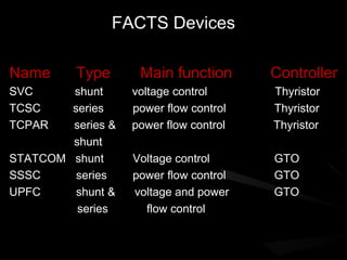
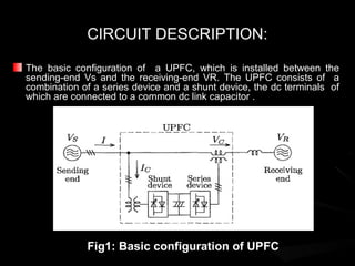
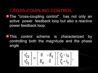
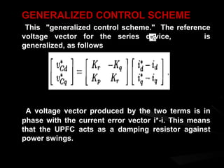
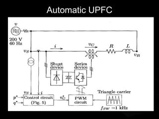
The UPFC is a FACTS device that can control all three parameters of line power flow - voltage, impedance, and phase angle. It consists of two voltage source inverters, one connected in series with the transmission line and one connected in shunt. The shunt inverter controls reactive power flow and voltage, while the series inverter controls real and reactive power flow by injecting a controllable voltage in series with the line. Control schemes for the UPFC include phase angle control, cross-coupling control, and a generalized control scheme that provides damping against power swings for improved stability. The UPFC offers benefits like improved power transfer capacity, transient stability, and independent control of real and reactive power flows.
Introduction to reactive power control in electrical powerDr.Raja R
Introduction to reactive power control in electrical power
Reactive power in transmission line :
Reactive power control
Reactive power and its importance
Apparent Power
Reactive Power
Apparent Power
Reactive Power Formula
Introduction to reactive power control in electrical powerDr.Raja R
Introduction to reactive power control in electrical power
Reactive power in transmission line :
Reactive power control
Reactive power and its importance
Apparent Power
Reactive Power
Apparent Power
Reactive Power Formula
The significance of power factor correction (PFC) has long been visualized as a technology requirement for improving the efficiency of a power system network by compensating for the fundamental reactive power generated or consumed by simple inductive or capacitive loads. With the Information Age in full swing, the growth of high reliability, low cost electronic products have led utilities to escalate their power quality concerns created by the increase of such “switching loads.” These products include: entertainment devices such as Digital TVs, DVDs, and audio equipment; information technology devices such as PCs, printers, and fax-machines; variable speed motor drives for HVAC and white goods appliances; food preparation and cooking products such as microwaves and cook tops; and lighting products, which include electronic ballasts, LED and fluorescent lamps, and other power conversion devices that operate a variety of lamps. The drivers that have resulted in this proliferation are a direct result of the availability of low-cost switch-mode devices and control circuitry in all major end-use segments: residential, commercial, and industrial.
Simulation Of Interline Power Flow Controller in Power Transmission Systemijsrd.com
The interline power flow controller (IPFC) is one of the latest generation flexible AC transmission systems (FACTS) controller used to control power flows of multiple transmission lines. The IPFC is the multifunction device, such as power flow control, voltage control, oscillation damping. This paper presents an overview and study and mathematical model of Interline Power Flow Control. The simulations of a simple power system of 500kV/230kV in MATLAB and simulation results are carried out on it. The results without and with IPFC are compared in terms of voltages, active and reactive power flows to demonstrate the performance of the IPFC model.
its a presentation describing all the major features and aspects of microgrids and their contribution in solving grotesque power crises situations.
hope one would find it helpful.
email your feedback at sumitraturi001@gmail.com.
MicroGrid and Energy Storage System COMPLETE DETAILS NEW PPT Abin Baby
A microgrid is a localized grouping of electricity generation, energy storage, and loads that normally operates connected to a traditional centralized grid (macrogrid). This single point of common coupling with the macrogrid can be disconnected. The microgrid can then function autonomously. Generation and loads in a microgrid are usually interconnected at low voltage. From the point of view of the grid operator, a connected microgrid can be controlled as if it were one entity.
Microgrid generation resources can include fuel cells, wind, solar, or other energy sources. The multiple dispersed generation sources and ability to isolate the microgrid from a larger network would provide highly reliable electric power. Produced heat from generation sources such as micro turbines could be used for local process heating or space heating, allowing flexible trade off between the needs for heat and electric power.
Flexible alternating current transmission systems (FACTs) technology opens up new opportunities for
controlling power flow and enhancing the usable capacity of present, as well as new and upgraded lines. These
FACTs device which enables independent control of active and reactive power besides improving reliability and
quality of the supply. This paper describes the real and reactive power flow control through a short transmission
line and then compensated short transmission line with different FACTs devices are used to selection of FACTs
devices for better reactive power compensation with change in line capacitance/shunt capacitance to observe
power flow. Computer simulation by MATLAB/SIMULINK has been used to determining better reactive power.
TCSC, STATCOM, UPFC and SSSC FACTs controller with different capacitance are tested for controlling
reactive power flow.
The electricity supply industry is undergoing a profound transformation worldwide. Market forces, scarcer natural resources, and an ever-increasing demand for electricity are some of the drivers responsible for such unprecedented change. Against this background of rapid evolution, the expansion programs of many utilities are being thwarted by a variety of well-founded, environment, land-use, and regulatory pressures that prevent the licensing and building of new transmission lines and electricity generating plants.
Transformer-Less UPFC for Wind Turbine ApplicationsIJMTST Journal
In this paper, an innovative technique with a new concept of transformer-less unified power flow controller
(UPFC) is implemented. The construction of the conventional UPFC that consists of two back-to-back inverters
which results in complexity and bulkiness which involves the transformers which are complication for
isolation & attaining high power rating with required output waveforms. To reduce a above problem to a
certain extent, a innovative transformer-less UPFC based on less complex configuration with two cascade
multilevel inverters (CMIs) has been proposed. Unified power flow controller (UPFC) has been the most
versatile Flexible AC Transmission System (FACTS) device due to its ability to control real and reactive power
80w on transmission lines while controlling the voltage of the bus to which it is connected. UPFC being a
multi-variable power system controller it is necessary to analyze its effect on power system operation. The
new UPFC offers several merits over the traditional technology, such as Transformer-less, Light weight, High
efficiency, Low cost & Fast dynamic response. This paper mainly highlights the modulation and control for
this innovative transformer-less UPFC, involving desired fundamental frequency modulation (FFM) for low
total harmonic distortion (THD), independent active and reactive power control over the transmission line,
dc-link voltage balance control, etc. The unique capabilities of the UPFC in multiple line compensation are
integrated into a generalized power flow controller that is able to maintain prescribed, and independently
controllable, real power & reactive power flow in the line. UPFC simply controls the magnitude and angular
position of the injected voltage in real time so as to maintain or vary the real and reactive power flow in the
line to satisfy load demand & system operating conditions. UPFC can control various power system
parameters, such as bus voltages and line flows. The impact of UPFC control modes and settings on the
power system reliability has not been addressed sufficiently yet. Cascade multilevel inverters has been
proposed to have an overview of producing the light weight STATCOM’s which enhances the power quality at
the output levels.When the multilevel converter is applied to STATCOM, each of the cascaded H-bridge
converters should be equipped with a galvanically isolated and floating dc capacitor without any power
source or circuit. This enables to eliminate a bulky, heavy, and costly line-frequency transformer from the
cascade STATCOM. When no UPFC is installed, interruption of either three-phase line due to a fault reduces
an active power flow to half, because the line impedance becomes double before the interruption. Installing
the UPFC makes it possible to control an amount of active power flowing through the transmission system.
Results has been shown through MATLAB Simulink
UPFC in order to Enhance the Power System ReliabilityIJMER
The maintenance and reliability of the power system has become a major aspect of study. The
solution is the use of FACTS devices especially the use of UPFC. Unified Power Flow Controller (UPFC)
is the most widely used FACTS device to control the power flow and to optimize the system stability in the
transmission line. It is used to control the power flow in the transmission systems by controlling the
impedance, voltage magnitude and phase angle. This controller offers advantages in terms of static and
dynamic operation of the power system. The UPFC with its various modes of operation is understood.
Second, the operation of control system used in its converters is also studied. Finally by help of modeling
of a power system in SIMULINK / MATLAB SIMPOWERSYSTEM and by installing single phase UPFC
in transmission link, its use as power flow controller and voltage injection and constructing a lab scale
model of UPFC is discussed also.
Performance and Analysis of Reactive Power Compensation by Unified Power Flow...ijeei-iaes
The Unified Power Flow Controller (UPFC) is the most versatile of the FACTS controllers envisaged so far. The main function of the UPFC is to control the flow of real and reactive power by injection of a voltage in series with the transmission line. Both the magnitude and the phase angle of the voltage can be varied independently. Real and Reactive power flow control can allow for power flow in prescribed routes, loading of transmission lines close to their thermal limits and can be utilized for improving transient and small signal stability of the power system. In this paper UPFC is incorporated in a SMIB (Single Machine Infinite Bus) system and the response of SMIB system has been recorded with and without UPFC, thereafter the comparison of both the output has been done. When no UPFC is installed, real and reactive power through the transmission line cannot be controlled. This paper presents control and performance of UPFC intended for installation on that transmission line to control power flow. Installing the UPFC makes it possible to control amount of active power flowing through the line. Simulations are carried out using MATLAB software to validate the performance of the UPFC.
POWER QUALITY IMPROVEMENT BY SSSC AND STATCOM USING PI CONTROLLERJournal For Research
This paper presents the enhancement of voltage stability using Static Synchronous compensator (STATCOM) and Static Synchronous series compensator (SSSC). In recent past years, along with the rapid increasing electrical power requirement has caused system to be heavily loaded leading to voltage instability. Under this condition there may be insufficient reactive power causing voltage to drop at various buses. The result would be the occurrence of voltage collapse which leads to total blackout of the whole system. FACT controllers have been used for solving various stability control problems. In this paper, SSSC and STATCOM are used to investigate the effect of these devices in controlling active and reactive powers to maintain voltage stability. The PI Controller is used to tune the circuit and to provide the zero signal error. Simulation results have been presented in MATLAB/Simulink environment for two machines four buses system.
1. Unified Power Flow
Controller
BY
Neha Kardam
M.Tech (Power System)
School Of Engineering
Gautam Buddha University,
Gr. Noida.
2. Contents
FACTS devices
Benefits of FACTS devices
Types of FACTS Devices
Introduction to UPFC
Circuit Description
Control schemes
Conclusion
3. FACTS
Flexible AC Transmission System (Facts) is
a new integrated concept based on power
electronic switching converters and dynamic
controllers to enhance the system utilization
and power transfer capacity as well as the
stability, security, reliability and power
quality of AC system interconnections .
4. BENEFITS OF FACTS
Regulation of power flows in prescribed
transmission routes.
Reduces the need for construction of new
transmission lines, capacitors and reactors.
Provides greater ability to transfer power between
controlled areas.
These devices help to damp the power oscillations
that could damage the equipment.
5. Improves the transient stability of the
system.
Controls real and reactive power flow in the
line independently.
Damping of oscillations which can threaten
security or limit the usable line capacity.
6. FACTS Devices
Name Type Main function Controller
SVC shunt voltage control Thyristor
TCSC series power flow control Thyristor
TCPAR series & power flow control Thyristor
shunt
STATCOM shunt Voltage control GTO
SSSC series power flow control GTO
UPFC shunt & voltage and power GTO
series flow control
7. INTRODUCTION TO UPFC
The UPFC is a device which can control simultaneously all
three parameters of line power flow
Such "new" FACTS device combines together the
features of two "old" FACTS devices:
1. STATCOM
2. SSSC
These two devices are two Voltage Source Inverters (VSI’s)
connected respectively in shunt with the transmission line
through a shunt transformer and in series with the
transmission line through a series transformer, connected to
each other by a common dc link including a storage
capacitor.
8. The shunt inverter is used for voltage regulation
at the point of connection injecting an opportune
reactive power flow into the line and to balance
the real power flow exchanged between the
series inverter and the transmission line.
The series inverter can be used to control the
real and reactive line power flow inserting an
opportune voltage with controllable magnitude
and phase in series with the transmission line.
9. CIRCUIT DESCRIPTION:
The basic configuration of a UPFC, which is installed between the
sending-end Vs and the receiving-end VR. The UPFC consists of a
combination of a series device and a shunt device, the dc terminals of
which are connected to a common dc link capacitor .
Fig1: Basic configuration of UPFC
10. FUNCTIONAL CONTROL OF SHUNT INVERTER
The shunt inverter is operating in such a way to inject a controllable
current Ic into the transmission line.
This current consist of two components with respect to the line voltage:
1. the real or direct component id
2. reactive or quadrature component iq
The direct component is automatically determined by the requirement to
balance the real power of the series inverter. The quadrature component,
instead, can be independently set to any desired reference level (inductive
or capacitive) within the capability of the inverter, to absorb or generate
respectively reactive power from the line. So, two control modes are
possible:
VAR control mode : the reference input is an inductive or capacitive var
request;
Automatic Voltage Control mode: the goal is to maintain the
transmission line voltage at the connection point to a reference value.
11. FUNCTIONAL CONTROL OF SERIES INVERTER
The series inverter injects a voltage, Vse which is controllable in
amplitude and phase angle in series with the transmission line.
This series voltage can be determined in different ways:
Direct Voltage Injection Mode: The reference inputs are directly the
magnitude and phase angle of the series voltage.
Phase Angle Shifter Emulation Mode: The reference input is phase
displacement between the sending end voltage and the receiving end
voltage.
Line Impedance Emulation Mode: The reference input is an
impedance value to insert in series with the line impedance.
Automatic Power flow Control Mode: The reference inputs are values
of P and Q to maintain on the transmission line despite system changes.
13. (a) Active power control (b) Reactive power control
Fig 3: Phasor diagrams in case of
active and reactive power
14. Control schemes
PHASE-ANGLE CONTROL
Adjusting the amplitude of the 90" leading or
lagging output voltage makes it possible to
control active power .
The d-q frame coordinates based on space
vectors, the d-axis current id corresponds to
active power, and so it can be controlled by the
q-axis voltage Vcq. Therefore, the reference
voltage vector for the series device is given by
………..
15. CROSS-COUPLING CONTROL
The "cross-coupling control" has not only an
active power feedback loop but also a reactive
power feedback loop.
This control scheme is characterized by
controlling both the magnitude and the phase
angle
16. GENERALIZED CONTROL SCHEME
This "generalized control scheme." The reference
voltage vector for the series device, is
generalized, as follows
A voltage vector produced by the two terms is in
phase with the current error vector i*-i. This means
that the UPFC acts as a damping resistor against
power swings.
18. CONCLUSION
Conventional power feedback control schemes make the
UPFC induce power fluctuations in transient states.
The time constant of damping is independent of the active
and reactive power feedback gains Kp and Kq.
The feedback gain Kr with a physical meaning of resistor is
effective in damping of power swings.
The proposed control scheme achieves quick response of
active and reactive power without causing power swings
and producing steady state errors.