Downloaded 760 times
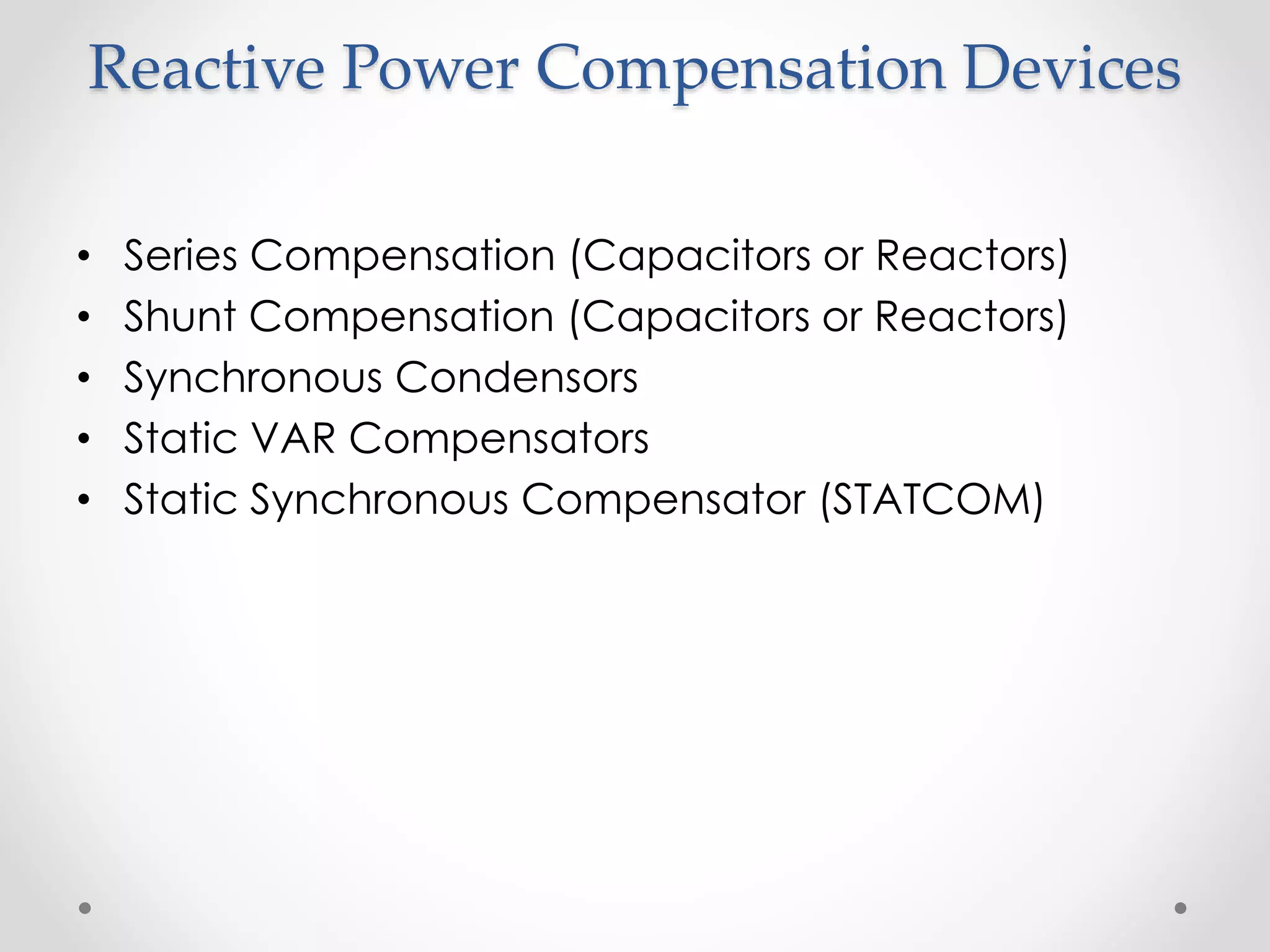
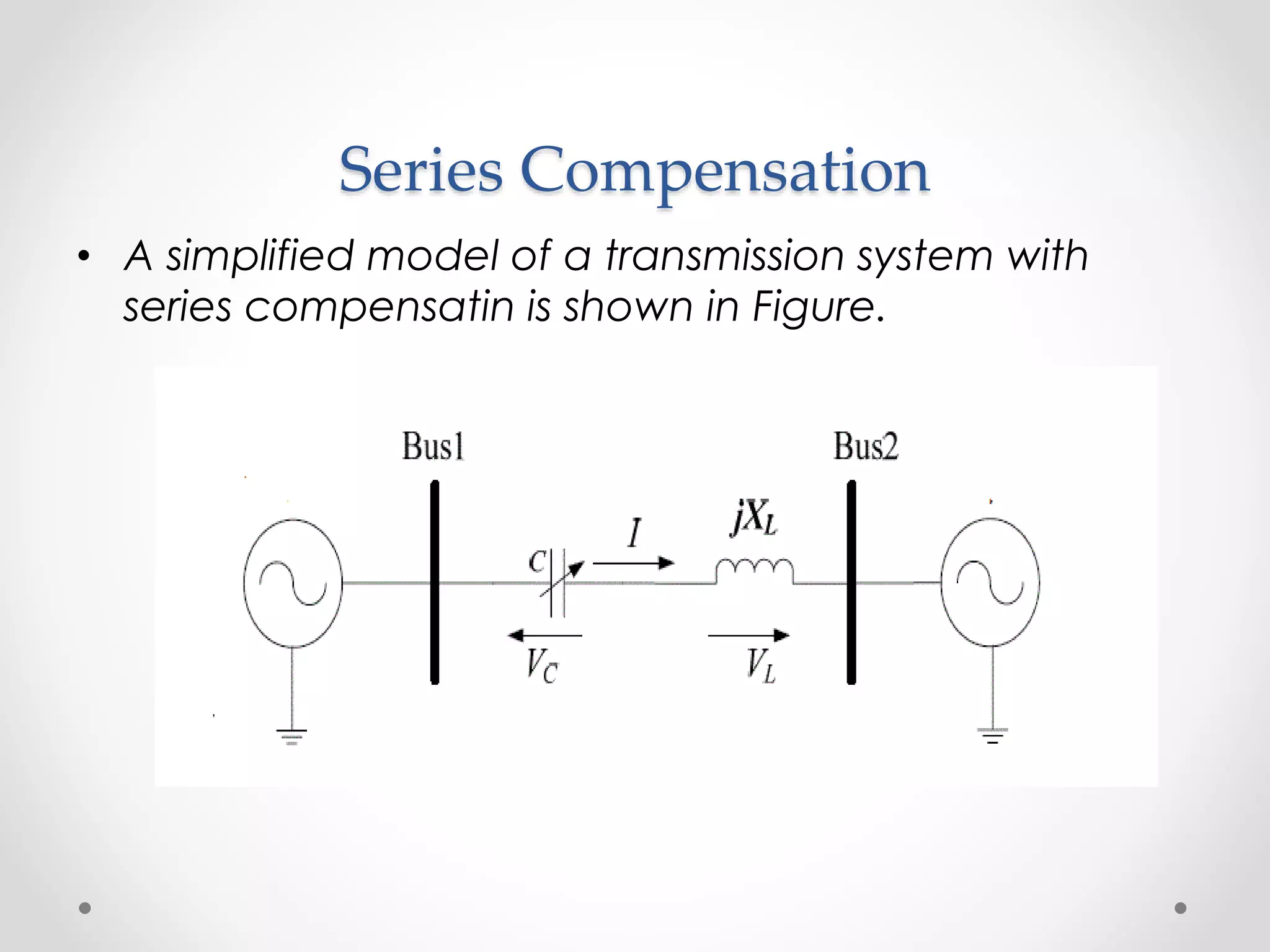
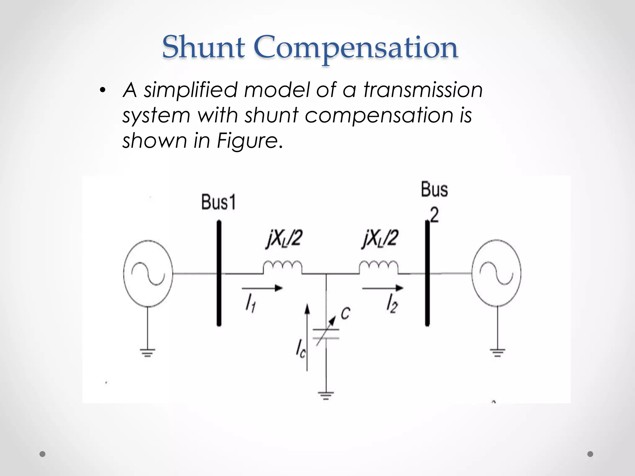
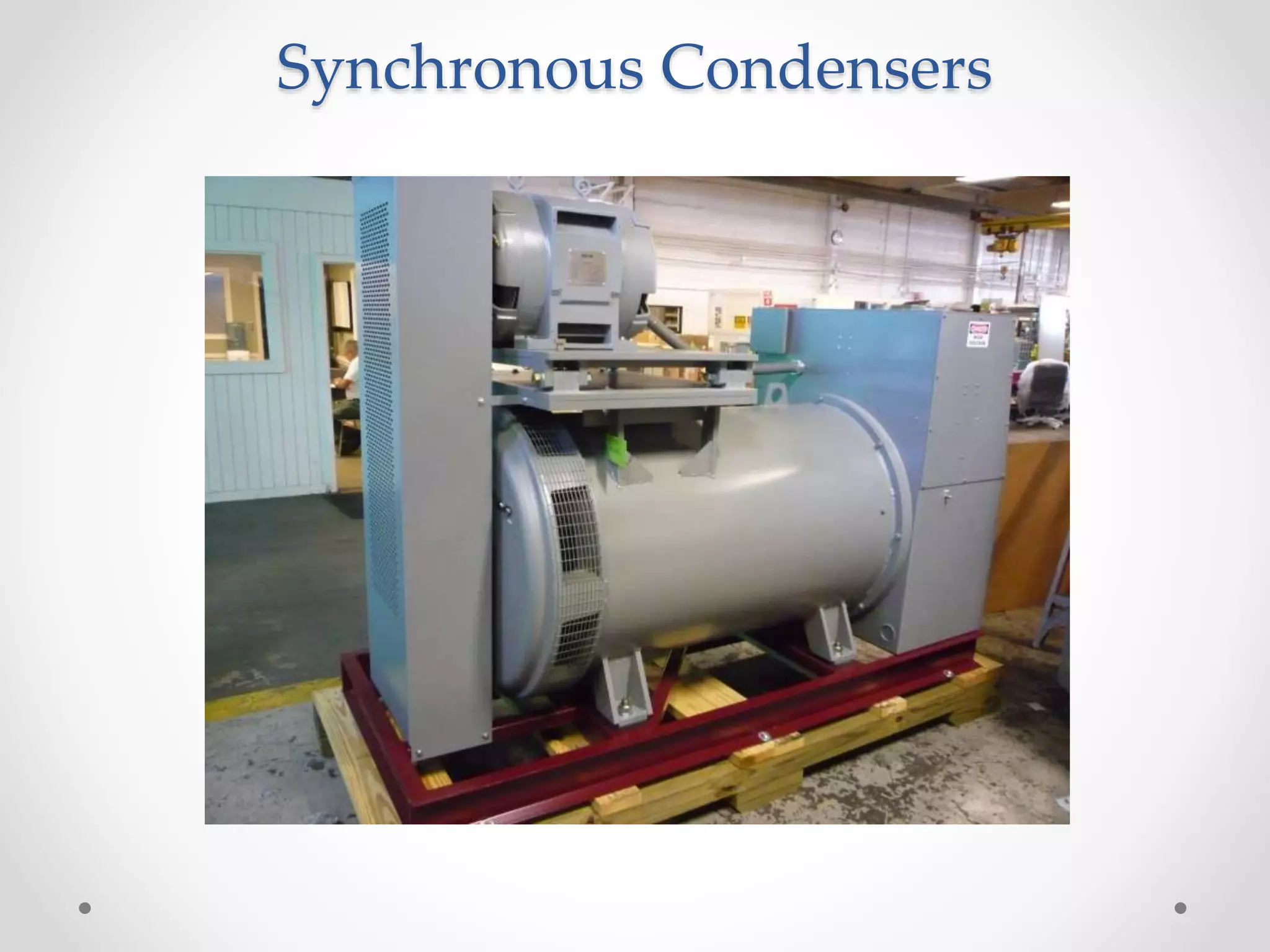
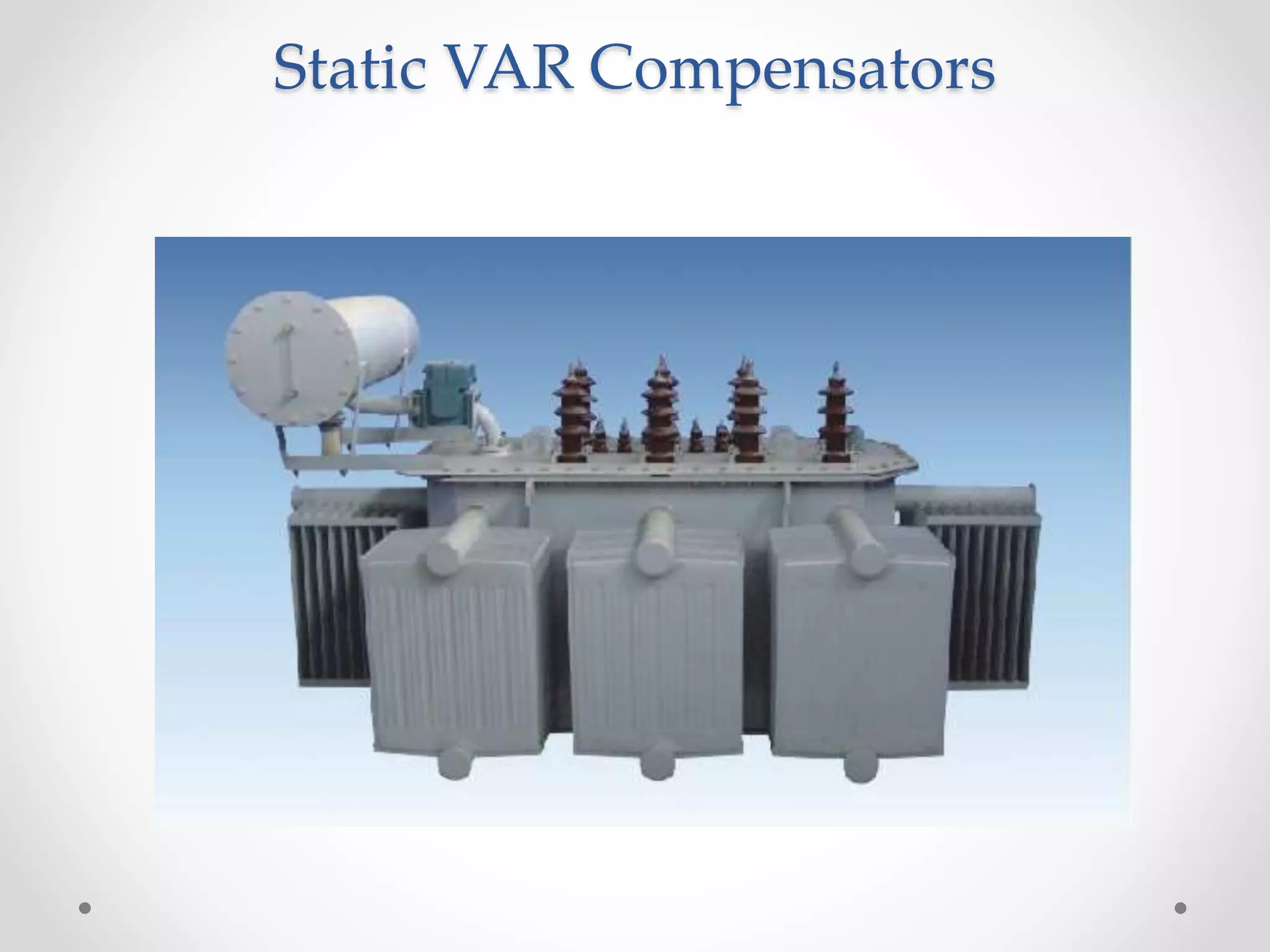

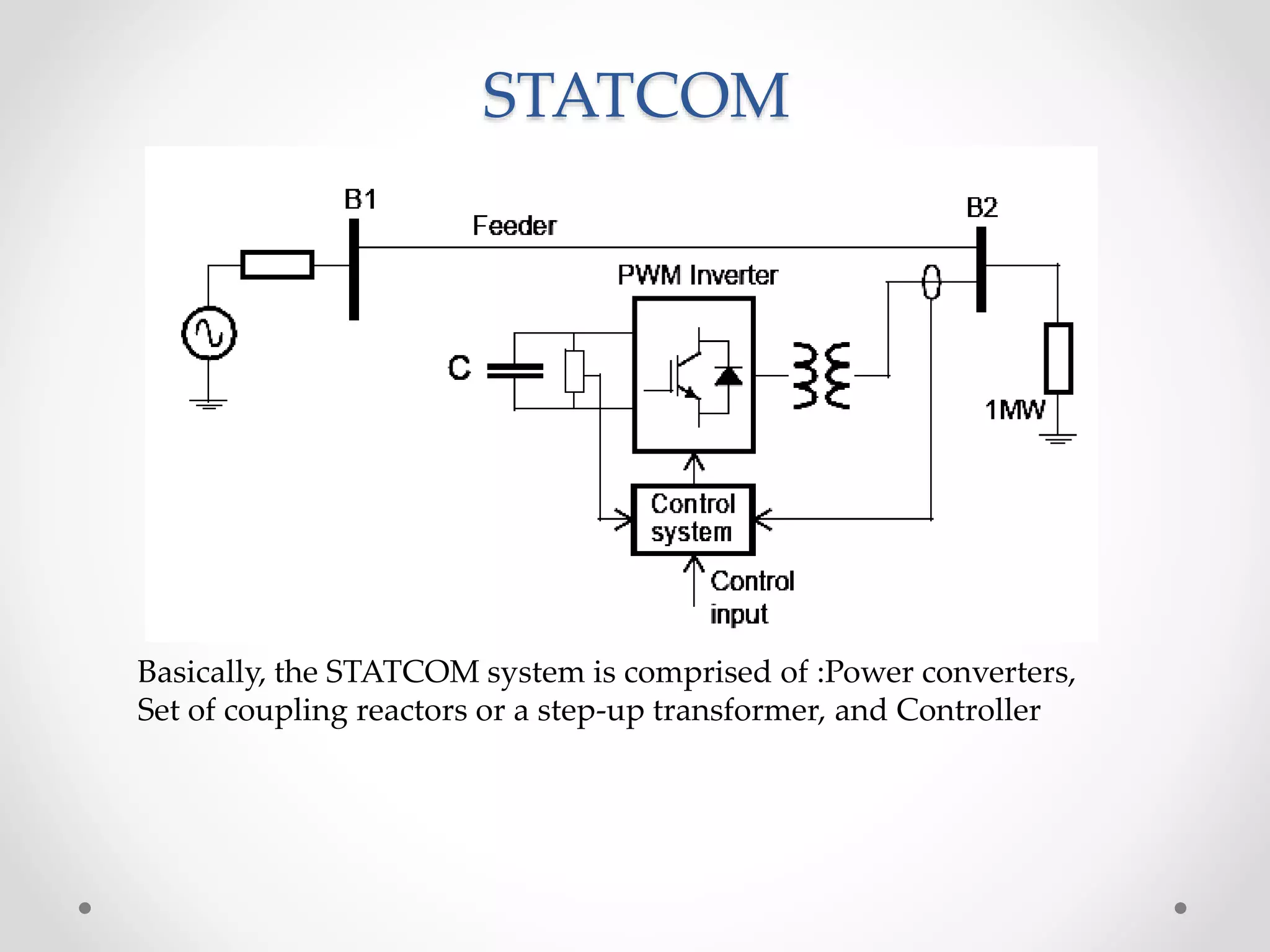
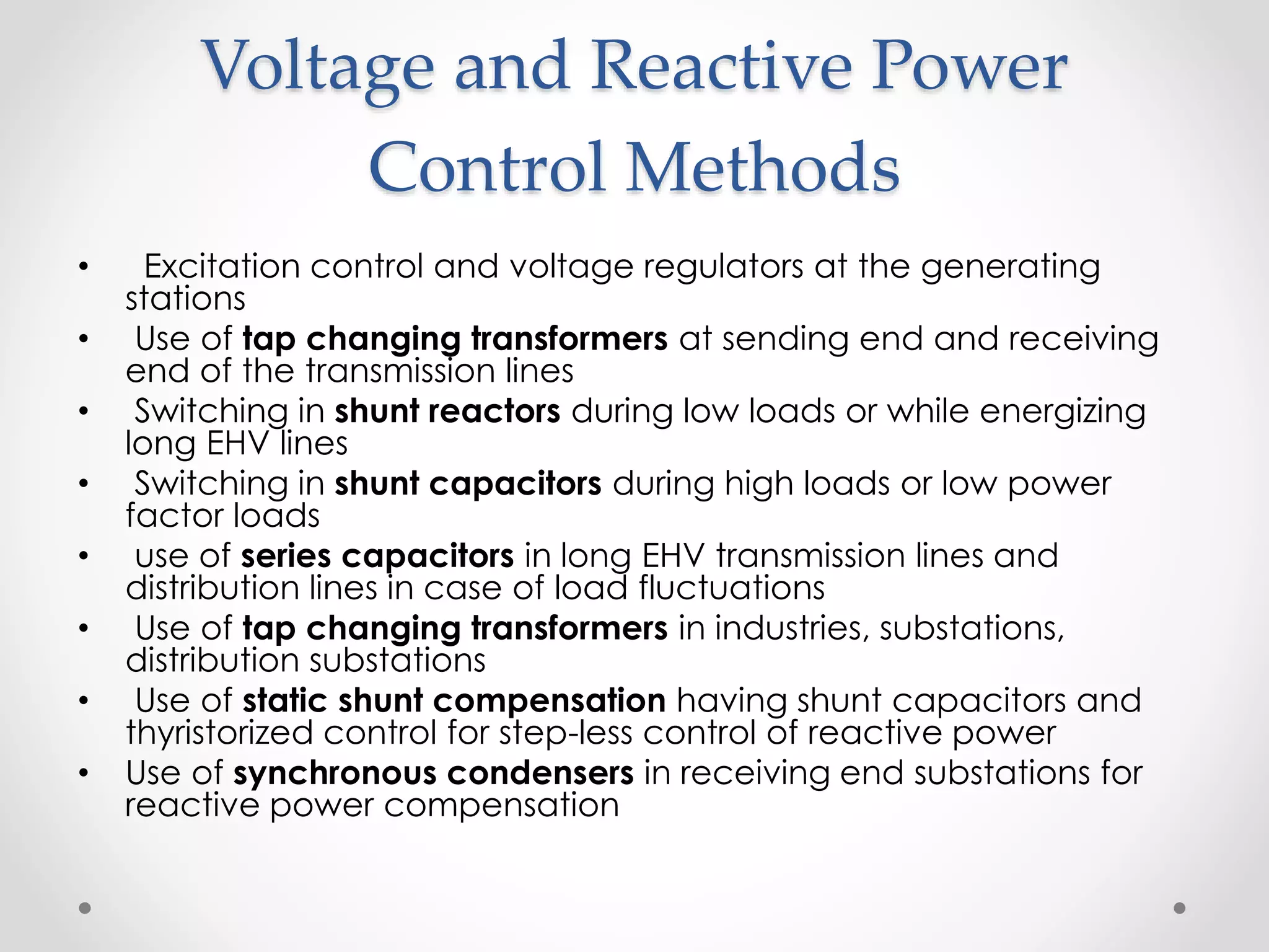


This document discusses voltage and reactive power control methods in power systems. It covers the need for reactive power to maintain voltage levels and deliver active power through transmission lines. Various reactive power compensation devices are described such as series and shunt capacitors/reactors, synchronous condensers, static VAR compensators, and static synchronous compensators. Common voltage and reactive power control methods include excitation control at generating stations, using tap changing transformers, and switching shunt reactors/capacitors depending on load levels.