Downloaded 809 times

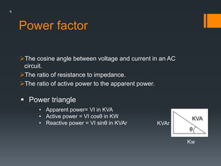
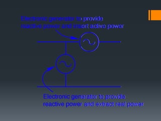
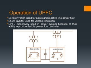


The seminar discusses power factor improvement using UPFC (Unified Power Flow Controller), highlighting the importance of power factor in electrical systems. It explains the effects of low power factor, benefits of FACTS (Flexible AC Transmission Systems), and describes the UPFC's operation and applications in enhancing power flow and system stability. Overall, the UPFC improves power factor, leading to better economic efficiency in power systems.