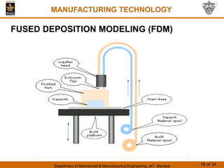
Department of Mechanical & Manufacturing Engineering, MIT, Manipal 1 of 24
MANUFACTURING TECHNOLOGY
CHAPTER 10
RAPID PROTOTYPING
MANUFACTURING TECHNOLOGY
Department of Mechanical & Manufacturing Engineering, MIT, Manipal 2 of 24
MANUFACTURING TECHNOLOGY
What is Rapid Prototyping?
• A CAD technique that allows “Automatic” creation of a
physical model or prototype from a 3-D model.
• A family of fabrication processes developed to make
engineering prototypes in minimum lead time based on a
CAD model of the item.
• Here material is added layer by layer to produce the part,
hence it is also termed as an additive process.
• The parts produced are not real prototypes as they are
made from materials whose properties are inferior to that
of the actual machine part
Department of Mechanical & Manufacturing Engineering, MIT, Manipal 3 of 24
MANUFACTURING TECHNOLOGY
What is Rapid Prototyping?
• Rapid Prototyping models can be used for testing
purposes.
• The materials used in Rapid Prototyping are limited and
dependent on the method chosen.
• Numerous plastics, ceramics, metals ranging from
stainless steel to titanium and wood like paper are some of
them.
Department of Mechanical & Manufacturing Engineering, MIT, Manipal 4 of 24
MANUFACTURING TECHNOLOGY
Why use Rapid Prototyping?
• Decreases lead time
• Traditional method is machining
• Can require significant lead-times – several weeks,
depending on part complexity and difficulty in ordering
materials
• Facilitates concurrent engineering
• Allows visualization of more ideas
Department of Mechanical & Manufacturing Engineering, MIT, Manipal 5 of 24
MANUFACTURING TECHNOLOGY
Why use Rapid Prototyping?
• Creating a prototype is an integral step in design
• A virtual prototype (a CAD model of the part) may not be
sufficient for the designer to visualize the part adequately
• Using RP to make the prototype, the designer can see and
feel the part and assess its merits and shortcomings
Department of Mechanical & Manufacturing Engineering, MIT, Manipal 6 of 24
MANUFACTURING TECHNOLOGY
Other names of Rapid Prototyping
• Layer manufacturing
• Direct CAD manufacturing
• Solid freeform fabrication
• Rapid prototyping and manufacturing (RPM)
• Additive Manufacturing
Department of Mechanical & Manufacturing Engineering, MIT, Manipal 7 of 24
MANUFACTURING TECHNOLOGY
Merits
• reduce prototype/production times from months to weeks/
days/hours
• a physical model is easier to sell to customers and
management
• Physical models are easier to check for errors
• avoids the high cost of prototype tooling, and allows
(more) design iterations
• prototypes costs can be lower than production types
Department of Mechanical & Manufacturing Engineering, MIT, Manipal 8 of 24
MANUFACTURING TECHNOLOGY
Demerits
• very expensive Investment/capital costs
• primary materials are specialized
• Low volume production
• Higher skill required for labour.
Department of Mechanical & Manufacturing Engineering, MIT, Manipal 9 of 24
MANUFACTURING TECHNOLOGY
STEREOLITHOGRAPHY (STL)
• RP process for fabricating a solid plastic part out of a
photosensitive liquid polymer using a directed laser beam
to solidify the polymer
• Part fabrication is accomplished as a series of layers - each
layer is added onto the previous layer to gradually build the
3-D geometry
• The first addition RP technology - introduced 1988 by 3D
Systems Inc. based on the work of Charles Hull
• More installations than any other RP method
Department of Mechanical & Manufacturing Engineering, MIT, Manipal 10 of 24
MANUFACTURING TECHNOLOGY
STEREOLITHOGRAPHY (STL)
Department of Mechanical & Manufacturing Engineering, MIT, Manipal 11 of 24
MANUFACTURING TECHNOLOGY
STEREOLITHOGRAPHY (STL)
• Stereolithography is the name of a process used to make
three-dimensional models from computer databases.
• Stereolithography uses a photochemical event to direct the
formation of points of plastic on the surface of an easily
solidified liquid.
• The computer directs a laser across the surface of a
polymerizable plastic converting the polymerizable material
point by point into a solid.
Department of Mechanical & Manufacturing Engineering, MIT, Manipal 12 of 24
MANUFACTURING TECHNOLOGY
STEREOLITHOGRAPHY (STL)
• This is done, in this particular experimental setup, on a
platform that is held a few millimeters under the surface of
the photo reactive liquid.
• After the laser has converted to solid plastic all the points in
one layer that are needed for the model, producing a two
dimensional lithograph of fixed z dimension, z, the platform
is dropped a small increment and a second layer is built on
top of the first.
Department of Mechanical & Manufacturing Engineering, MIT, Manipal 13 of 24
MANUFACTURING TECHNOLOGY
STEREOLITHOGRAPHY (STL)
• This process continues until each layer of the computer
graphic, or plan, is converted to solid plastic. When the
process is complete the model can be lifted from the plastic
vat as an exact replica of the computer graphic.
• Excess polymer is removed with alcohol and light sanding
is sometimes used to improve the appearance.
Department of Mechanical & Manufacturing Engineering, MIT, Manipal 14 of 24
MANUFACTURING TECHNOLOGY
STEREOLITHOGRAPHY (STL)
• One of the most important uses of stereolithography is in
making replicas of medical data, such as CT scans and
MRI scans, for surgical planning.
• Stereolithography generally is considered to provide the
greatest accuracy and best surface finish of any rapid
prototyping technology.
Department of Mechanical & Manufacturing Engineering, MIT, Manipal 15 of 24
MANUFACTURING TECHNOLOGY
FUSED DEPOSITION MODELING (FDM)
• RP process in which a long filament of wax or polymer is
extruded onto existing part surface from a work head to
complete each new layer
• Work head is controlled in the x-y plane during each layer
and then moves up by a distance equal to one layer in the
z-direction
• Extrudate is solidified and cold welded to the cooler part
surface in about 0.1 s
• Part is fabricated from the base up, using a layer-by-layer
procedure
Department of Mechanical & Manufacturing Engineering, MIT, Manipal 16 of 24
MANUFACTURING TECHNOLOGY
FUSED DEPOSITION MODELING (FDM)
Department of Mechanical & Manufacturing Engineering, MIT, Manipal 17 of 24
MANUFACTURING TECHNOLOGY
FUSED DEPOSITION MODELING (FDM)
• FDM starts with a 3D CAD model sliced into thin layers in
Z-axis. These sliced layers are used to drive an extrusion
head of FDM machine.
• The building material, in the form of a thin solid filament, is
fed from a spool to a movable head controlled by motors.
• Second filament is fed from an adjacent nozzle for support
material, it is used to give support for overhanged or
cantilever features.
• The filament reaches the liquifier head, melts it and then
gets extruded through a nozzle onto the part surface.
Department of Mechanical & Manufacturing Engineering, MIT, Manipal 18 of 24
MANUFACTURING TECHNOLOGY
FUSED DEPOSITION MODELING (FDM)
• After covering the whole cross section, the platform
descends by one layer thickness to lay down the next layer.
Process repeats itself until full 3D part is formed.
• The temperature of machine chamber is precisely
controlled below the melting point of the material so that
only little amount of heat is required to melt the filament
and on the other hand part need to be kept cool enough so
that the molten material solidifies upon contact.
• FDM is the second most widely used rapid prototyping
technology, after stereolithography.
Department of Mechanical & Manufacturing Engineering, MIT, Manipal 19 of 24
MANUFACTURING TECHNOLOGY
SELECTIVE LASER SINTERING (SLS)
• Moving laser beam sinters heat fusible powders in areas
corresponding to the CAD geometry model one layer at a
time to build the solid part
• After each layer is completed, a new layer of loose powders
is spread across the surface
• Layer by layer, the powders are gradually bonded by the
laser beam into a solid mass that forms the 3-D part
geometry
• In areas not sintered, the powders are loose and can be
poured out of completed part
Department of Mechanical & Manufacturing Engineering, MIT, Manipal 20 of 24
MANUFACTURING TECHNOLOGY
SELECTIVE LASER SINTERING (SLS)
Department of Mechanical & Manufacturing Engineering, MIT, Manipal 21 of 24
MANUFACTURING TECHNOLOGY
SELECTIVE LASER SINTERING (SLS)
• SLS process produces parts directly from 3D CAD model,
layer by layer similar wherein a resin powder is used.
• The CO2 Laser provides a concentrated heating beam
which is traced over the tightly compacted layer of fine
heat-fusible powder. The temperature in the entire chamber
is maintained little below the melting point of the powder.
• So laser slightly raises the temperature to cause sintering
that is, welding is carried out without melting.

Rapid prototyping.pdf .

  • 1.
    Department of Mechanical& Manufacturing Engineering, MIT, Manipal 1 of 24 MANUFACTURING TECHNOLOGY CHAPTER 10 RAPID PROTOTYPING MANUFACTURING TECHNOLOGY
  • 2.
    Department of Mechanical& Manufacturing Engineering, MIT, Manipal 2 of 24 MANUFACTURING TECHNOLOGY What is Rapid Prototyping? • A CAD technique that allows “Automatic” creation of a physical model or prototype from a 3-D model. • A family of fabrication processes developed to make engineering prototypes in minimum lead time based on a CAD model of the item. • Here material is added layer by layer to produce the part, hence it is also termed as an additive process. • The parts produced are not real prototypes as they are made from materials whose properties are inferior to that of the actual machine part
  • 3.
    Department of Mechanical& Manufacturing Engineering, MIT, Manipal 3 of 24 MANUFACTURING TECHNOLOGY What is Rapid Prototyping? • Rapid Prototyping models can be used for testing purposes. • The materials used in Rapid Prototyping are limited and dependent on the method chosen. • Numerous plastics, ceramics, metals ranging from stainless steel to titanium and wood like paper are some of them.
  • 4.
    Department of Mechanical& Manufacturing Engineering, MIT, Manipal 4 of 24 MANUFACTURING TECHNOLOGY Why use Rapid Prototyping? • Decreases lead time • Traditional method is machining • Can require significant lead-times – several weeks, depending on part complexity and difficulty in ordering materials • Facilitates concurrent engineering • Allows visualization of more ideas
  • 5.
    Department of Mechanical& Manufacturing Engineering, MIT, Manipal 5 of 24 MANUFACTURING TECHNOLOGY Why use Rapid Prototyping? • Creating a prototype is an integral step in design • A virtual prototype (a CAD model of the part) may not be sufficient for the designer to visualize the part adequately • Using RP to make the prototype, the designer can see and feel the part and assess its merits and shortcomings
  • 6.
    Department of Mechanical& Manufacturing Engineering, MIT, Manipal 6 of 24 MANUFACTURING TECHNOLOGY Other names of Rapid Prototyping • Layer manufacturing • Direct CAD manufacturing • Solid freeform fabrication • Rapid prototyping and manufacturing (RPM) • Additive Manufacturing
  • 7.
    Department of Mechanical& Manufacturing Engineering, MIT, Manipal 7 of 24 MANUFACTURING TECHNOLOGY Merits • reduce prototype/production times from months to weeks/ days/hours • a physical model is easier to sell to customers and management • Physical models are easier to check for errors • avoids the high cost of prototype tooling, and allows (more) design iterations • prototypes costs can be lower than production types
  • 8.
    Department of Mechanical& Manufacturing Engineering, MIT, Manipal 8 of 24 MANUFACTURING TECHNOLOGY Demerits • very expensive Investment/capital costs • primary materials are specialized • Low volume production • Higher skill required for labour.
  • 9.
    Department of Mechanical& Manufacturing Engineering, MIT, Manipal 9 of 24 MANUFACTURING TECHNOLOGY STEREOLITHOGRAPHY (STL) • RP process for fabricating a solid plastic part out of a photosensitive liquid polymer using a directed laser beam to solidify the polymer • Part fabrication is accomplished as a series of layers - each layer is added onto the previous layer to gradually build the 3-D geometry • The first addition RP technology - introduced 1988 by 3D Systems Inc. based on the work of Charles Hull • More installations than any other RP method
  • 10.
    Department of Mechanical& Manufacturing Engineering, MIT, Manipal 10 of 24 MANUFACTURING TECHNOLOGY STEREOLITHOGRAPHY (STL)
  • 11.
    Department of Mechanical& Manufacturing Engineering, MIT, Manipal 11 of 24 MANUFACTURING TECHNOLOGY STEREOLITHOGRAPHY (STL) • Stereolithography is the name of a process used to make three-dimensional models from computer databases. • Stereolithography uses a photochemical event to direct the formation of points of plastic on the surface of an easily solidified liquid. • The computer directs a laser across the surface of a polymerizable plastic converting the polymerizable material point by point into a solid.
  • 12.
    Department of Mechanical& Manufacturing Engineering, MIT, Manipal 12 of 24 MANUFACTURING TECHNOLOGY STEREOLITHOGRAPHY (STL) • This is done, in this particular experimental setup, on a platform that is held a few millimeters under the surface of the photo reactive liquid. • After the laser has converted to solid plastic all the points in one layer that are needed for the model, producing a two dimensional lithograph of fixed z dimension, z, the platform is dropped a small increment and a second layer is built on top of the first.
  • 13.
    Department of Mechanical& Manufacturing Engineering, MIT, Manipal 13 of 24 MANUFACTURING TECHNOLOGY STEREOLITHOGRAPHY (STL) • This process continues until each layer of the computer graphic, or plan, is converted to solid plastic. When the process is complete the model can be lifted from the plastic vat as an exact replica of the computer graphic. • Excess polymer is removed with alcohol and light sanding is sometimes used to improve the appearance.
  • 14.
    Department of Mechanical& Manufacturing Engineering, MIT, Manipal 14 of 24 MANUFACTURING TECHNOLOGY STEREOLITHOGRAPHY (STL) • One of the most important uses of stereolithography is in making replicas of medical data, such as CT scans and MRI scans, for surgical planning. • Stereolithography generally is considered to provide the greatest accuracy and best surface finish of any rapid prototyping technology.
  • 15.
    Department of Mechanical& Manufacturing Engineering, MIT, Manipal 15 of 24 MANUFACTURING TECHNOLOGY FUSED DEPOSITION MODELING (FDM) • RP process in which a long filament of wax or polymer is extruded onto existing part surface from a work head to complete each new layer • Work head is controlled in the x-y plane during each layer and then moves up by a distance equal to one layer in the z-direction • Extrudate is solidified and cold welded to the cooler part surface in about 0.1 s • Part is fabricated from the base up, using a layer-by-layer procedure
  • 16.
    Department of Mechanical& Manufacturing Engineering, MIT, Manipal 16 of 24 MANUFACTURING TECHNOLOGY FUSED DEPOSITION MODELING (FDM)
  • 17.
    Department of Mechanical& Manufacturing Engineering, MIT, Manipal 17 of 24 MANUFACTURING TECHNOLOGY FUSED DEPOSITION MODELING (FDM) • FDM starts with a 3D CAD model sliced into thin layers in Z-axis. These sliced layers are used to drive an extrusion head of FDM machine. • The building material, in the form of a thin solid filament, is fed from a spool to a movable head controlled by motors. • Second filament is fed from an adjacent nozzle for support material, it is used to give support for overhanged or cantilever features. • The filament reaches the liquifier head, melts it and then gets extruded through a nozzle onto the part surface.
  • 18.
    Department of Mechanical& Manufacturing Engineering, MIT, Manipal 18 of 24 MANUFACTURING TECHNOLOGY FUSED DEPOSITION MODELING (FDM) • After covering the whole cross section, the platform descends by one layer thickness to lay down the next layer. Process repeats itself until full 3D part is formed. • The temperature of machine chamber is precisely controlled below the melting point of the material so that only little amount of heat is required to melt the filament and on the other hand part need to be kept cool enough so that the molten material solidifies upon contact. • FDM is the second most widely used rapid prototyping technology, after stereolithography.
  • 19.
    Department of Mechanical& Manufacturing Engineering, MIT, Manipal 19 of 24 MANUFACTURING TECHNOLOGY SELECTIVE LASER SINTERING (SLS) • Moving laser beam sinters heat fusible powders in areas corresponding to the CAD geometry model one layer at a time to build the solid part • After each layer is completed, a new layer of loose powders is spread across the surface • Layer by layer, the powders are gradually bonded by the laser beam into a solid mass that forms the 3-D part geometry • In areas not sintered, the powders are loose and can be poured out of completed part
  • 20.
    Department of Mechanical& Manufacturing Engineering, MIT, Manipal 20 of 24 MANUFACTURING TECHNOLOGY SELECTIVE LASER SINTERING (SLS)
  • 21.
    Department of Mechanical& Manufacturing Engineering, MIT, Manipal 21 of 24 MANUFACTURING TECHNOLOGY SELECTIVE LASER SINTERING (SLS) • SLS process produces parts directly from 3D CAD model, layer by layer similar wherein a resin powder is used. • The CO2 Laser provides a concentrated heating beam which is traced over the tightly compacted layer of fine heat-fusible powder. The temperature in the entire chamber is maintained little below the melting point of the powder. • So laser slightly raises the temperature to cause sintering that is, welding is carried out without melting.