Downloaded 2,427 times
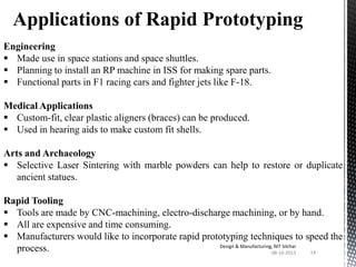
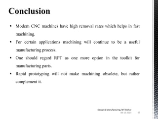

The document presents an overview of rapid prototyping technology. It discusses how rapid prototyping directly converts 3D computer models into physical models layer by layer, allowing for faster production of prototypes with high accuracy. Several major rapid prototyping techniques are described, including stereolithography, laminated object manufacturing, selective laser sintering, and fused deposition modeling. Applications of rapid prototyping in engineering, medicine, arts, and rapid tooling are also outlined.