Downloaded 404 times
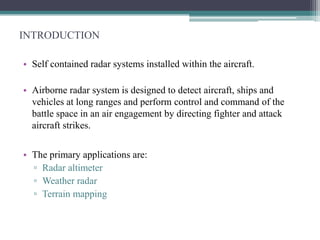
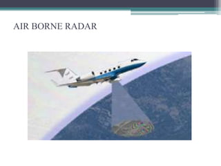
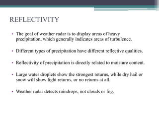
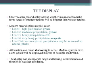
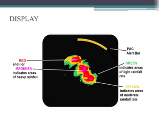

Airborne radar systems installed in aircraft can detect objects at long ranges and support air combat operations. There are four main types of airborne radar: radar altimeter to measure height above ground, weather radar to detect precipitation, terrain mapping radar, and ground moving target indication radar. Weather radar emits radio waves that reflect off rain droplets and snow crystals, displaying them in color-coded levels of reflectivity on the cockpit display. Pilots use controls to adjust the radar range, gain, and tilt to optimize weather detection and avoidance.