Download as PDF, PPTX

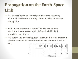
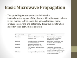
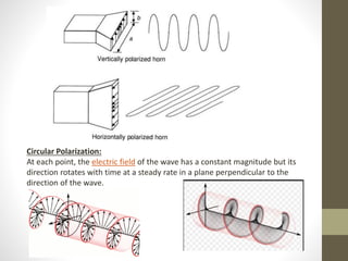
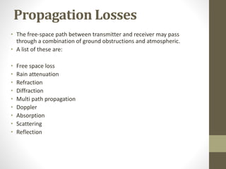

This document discusses key concepts in microwave link engineering including propagation on earth-space links, basic microwave propagation principles, isotropic radiators, directional properties of antennas, polarization, and propagation losses. It describes how radio waves propagate through space and interact with matter, defines near and far field regions, and explores concepts like directivity, gain, beamwidth, sidelobes, and the effects of different types of polarization. It provides examples of horizontal and circular polarization and lists various factors that can cause propagation losses.


