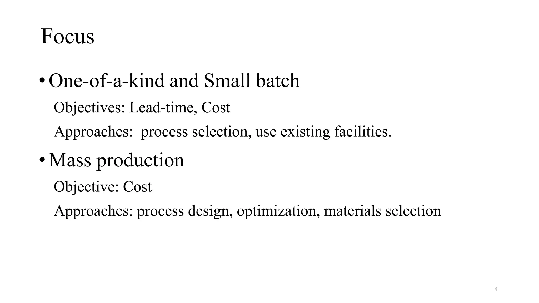
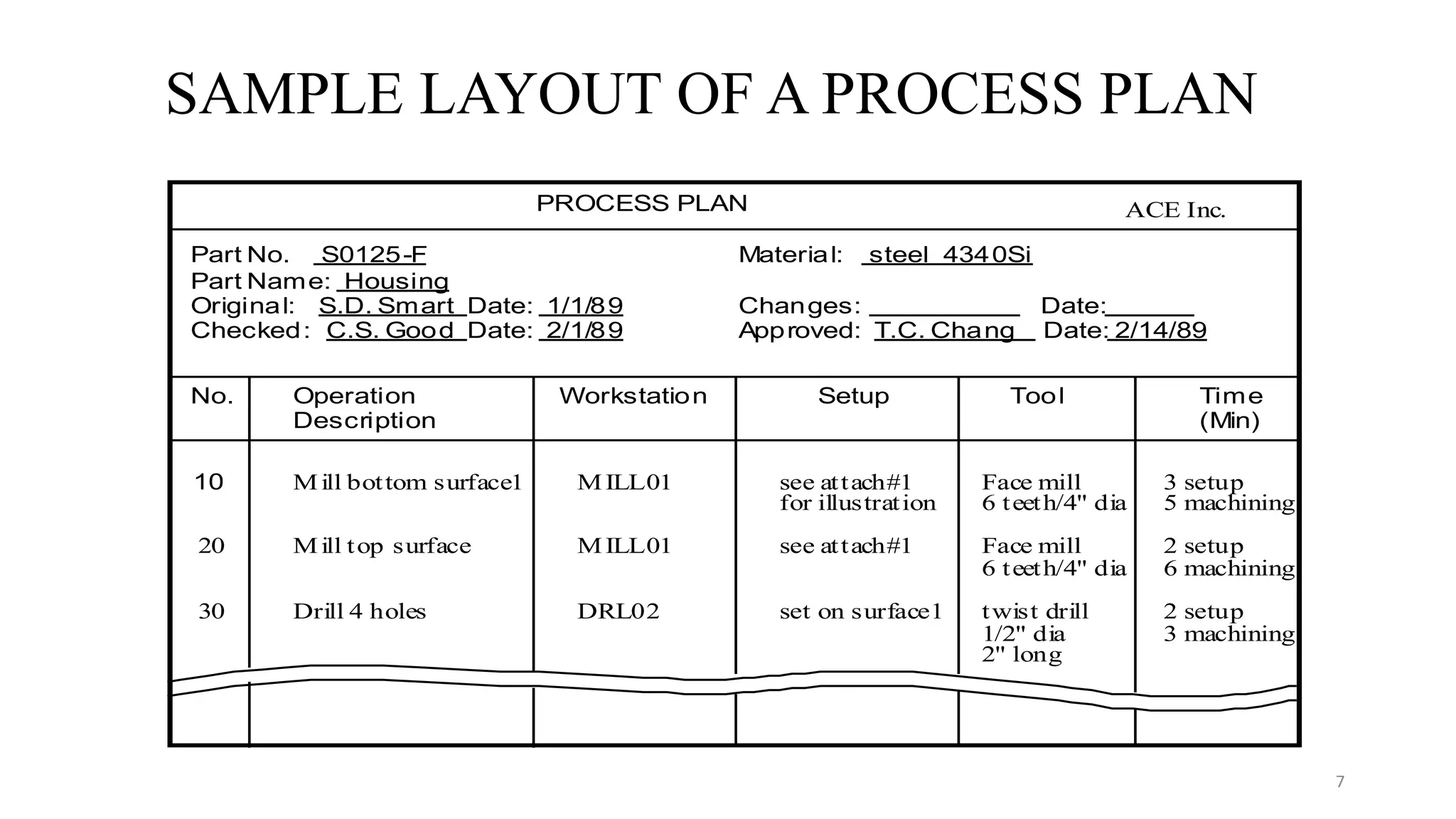
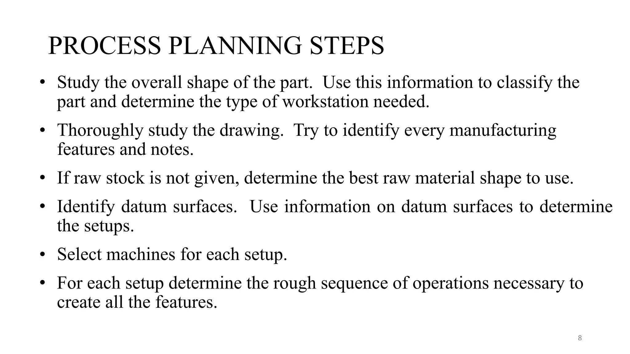
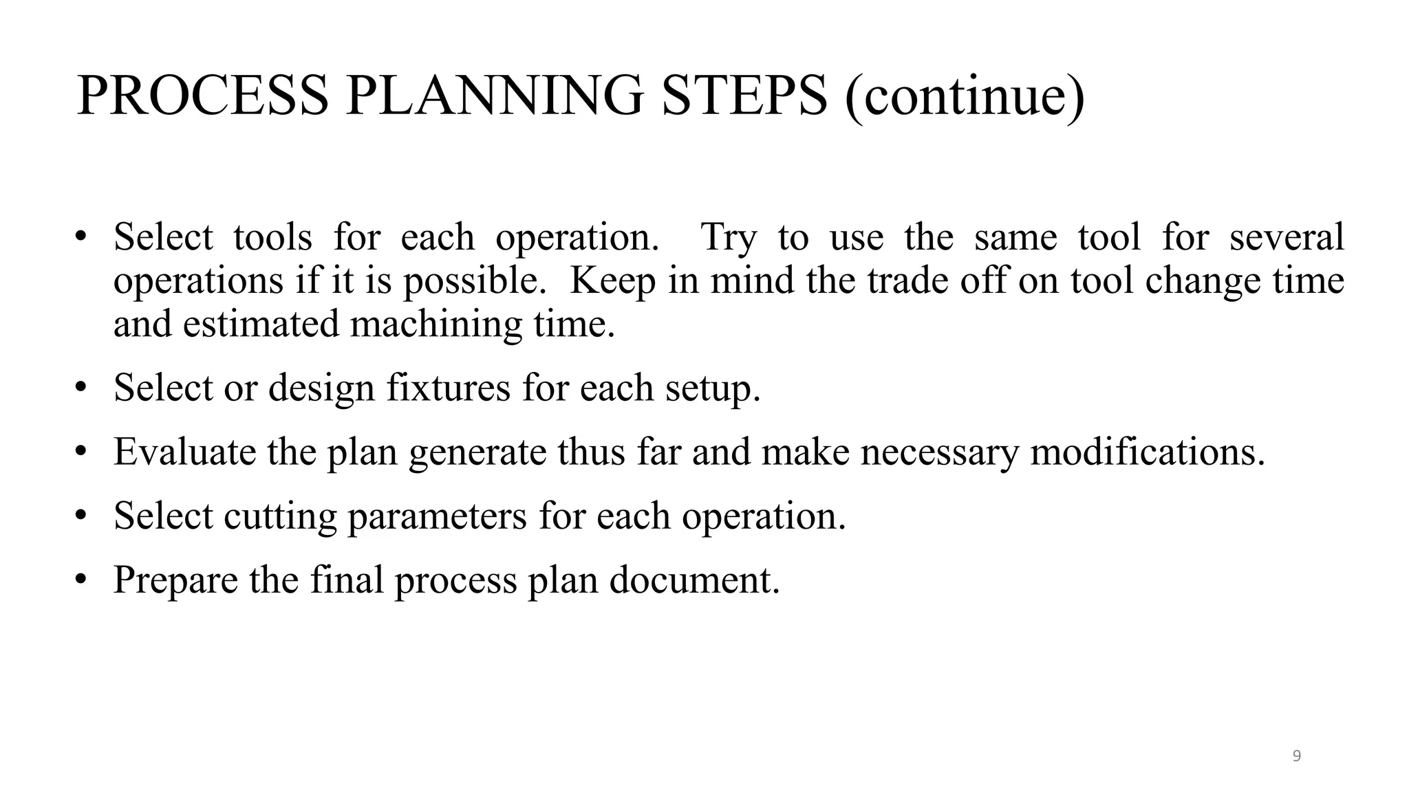
PROCESS PLANNING
Presented
by
Hiran Gabriel D J
1
PROCESS ENGINEERING and PLANNING
• The act of preparing detailed work instructions to produce a part.
• Process planning is also called: manufacturing planning, process
planning, material processing, process engineering, and machine
routing.
• Which machining processes and parameters are to be used (as well as
those machines capable of performing these processes) to convert
(machine) a piece part from its initial form to a final form
predetermined (usually by a design engineer) from an engineering
drawing.
2
PROCESS PLANNING
Design Machine
Tool
Scheduling and Production Control
Process
Planning
3
Focus
•One-of-a-kind and Small batch
Objectives: Lead-time, Cost
Approaches: process selection, use existing facilities.
•Mass production
Objective: Cost
Approaches: process design, optimization, materials selection
4
How do we process a product ?
• How can we make it ?
• How much does it cost ?
• How long will it take us to complete it ?
• How reliable will it be ?
• How can we recycle it ?
5
INTERACTION OF PLANNING FUNCTIONS
GEOMETRIC REASONING
PROCESS SELECTION
CUTTER SELECTION
MACHINE TOOL SELECTION
SETUP PLANNING
FIXTURE PLANNING
CUTTER PATH GENERATION
• global & local geometry
• process capability
• process cost
• available tools
• tool dimension and geometry
• geometric constraints
• machine availability, cost
• machine capability
• feature relationship
• approach directions
• process constraints
• fixture constraints
• fixture element function
• locating, supporting, and
clamping surfaces
• stability
• feature merging and split
• path optimization
• obstacle and interference
avoidance
6
SAMPLE LAYOUT OF A PROCESS PLAN
PROCESS PLAN ACE Inc.
Part No. S0125-F
Part Name: Housing
Original: S.D. Smart Date: 1/1/89
Checked: C.S. Good Date: 2/1/89
Material: steel 4340Si
Changes: Date:
Approved: T.C. Chang Date: 2/14/89
No. Operation
Description
Workstation Setup Tool Time
(Min)
10 Mill bottom surface1 MILL01 see attach#1
for illustration
Face mill
6 teeth/4" dia
3 setup
5 machining
20 Mill top surface MILL01 see attach#1 Face mill
6 teeth/4" dia
2 setup
6 machining
30 Drill 4 holes DRL02 set on surface1 twist drill
1/2" dia
2" long
2 setup
3 machining
7
PROCESS PLANNING STEPS
• Study the overall shape of the part. Use this information to classify the
part and determine the type of workstation needed.
• Thoroughly study the drawing. Try to identify every manufacturing
features and notes.
• If raw stock is not given, determine the best raw material shape to use.
• Identify datum surfaces. Use information on datum surfaces to determine
the setups.
• Select machines for each setup.
• For each setup determine the rough sequence of operations necessary to
create all the features.
8
PROCESS PLANNING STEPS (continue)
• Select tools for each operation. Try to use the same tool for several
operations if it is possible. Keep in mind the trade off on tool change time
and estimated machining time.
• Select or design fixtures for each setup.
• Evaluate the plan generate thus far and make necessary modifications.
• Select cutting parameters for each operation.
• Prepare the final process plan document.
9
Work Piece
10
Final Product
11
Part no 12345 Material
Part name impeller changes
Original Date 21-03-2019
checked Aproval
Operation No.
Operation
description
Workstation Setup Tool Time
10 Facing ⌀28mm Lathe - 1 Side -1 Turning tool 30 + 15
20 Facing ⌀60mm Lathe - 1 Side -1 Turning tool 10
30 Facing ⌀96mm Lathe - 1 Side -1 Turning tool 20
40
Turning
⌀28.2mm
Lathe - 1 Side -1 Turning tool 25
50
Finish turning
⌀28mm
Lathe - 1 Side -1 Turning tool 15
60
Turning
⌀60.2mm
Lathe - 1 Side -1 Turning tool 25
70
Finish turning
⌀60mm
Lathe - 1 Side -1 Turning tool 15
80
Turning
⌀96.2mm
Lathe - 1 Side -1 Turning tool 30
90
Finish turning
⌀96mm
Lathe - 1 Side -1 Turning tool 20
100
Turning
⌀96.2mm
Lathe - 1 Side -2 Turning tool 30 + 25
110
Finish turning
⌀96mm
Lathe - 1 Side -2 Turning tool 20
120
Turning
⌀28.2mm
Lathe - 1 Side -2 Turning tool 25
130
Finish turning
⌀28mm
Lathe - 1 Side -2 Turning tool 15
140 Boring ⌀20mm Lathe - 1 Side -2 Boring tool 20 + 25
150
Key way
Broaching
vertical
broaching
Side -1
Linear broaching
tool
30 + 60
Process Plan PSG Pumps
12

Process planning with an example

  • 1.
  • 2.
    PROCESS ENGINEERING andPLANNING • The act of preparing detailed work instructions to produce a part. • Process planning is also called: manufacturing planning, process planning, material processing, process engineering, and machine routing. • Which machining processes and parameters are to be used (as well as those machines capable of performing these processes) to convert (machine) a piece part from its initial form to a final form predetermined (usually by a design engineer) from an engineering drawing. 2
  • 3.
    PROCESS PLANNING Design Machine Tool Schedulingand Production Control Process Planning 3
  • 4.
    Focus •One-of-a-kind and Smallbatch Objectives: Lead-time, Cost Approaches: process selection, use existing facilities. •Mass production Objective: Cost Approaches: process design, optimization, materials selection 4
  • 5.
    How do weprocess a product ? • How can we make it ? • How much does it cost ? • How long will it take us to complete it ? • How reliable will it be ? • How can we recycle it ? 5
  • 6.
    INTERACTION OF PLANNINGFUNCTIONS GEOMETRIC REASONING PROCESS SELECTION CUTTER SELECTION MACHINE TOOL SELECTION SETUP PLANNING FIXTURE PLANNING CUTTER PATH GENERATION • global & local geometry • process capability • process cost • available tools • tool dimension and geometry • geometric constraints • machine availability, cost • machine capability • feature relationship • approach directions • process constraints • fixture constraints • fixture element function • locating, supporting, and clamping surfaces • stability • feature merging and split • path optimization • obstacle and interference avoidance 6
  • 7.
    SAMPLE LAYOUT OFA PROCESS PLAN PROCESS PLAN ACE Inc. Part No. S0125-F Part Name: Housing Original: S.D. Smart Date: 1/1/89 Checked: C.S. Good Date: 2/1/89 Material: steel 4340Si Changes: Date: Approved: T.C. Chang Date: 2/14/89 No. Operation Description Workstation Setup Tool Time (Min) 10 Mill bottom surface1 MILL01 see attach#1 for illustration Face mill 6 teeth/4" dia 3 setup 5 machining 20 Mill top surface MILL01 see attach#1 Face mill 6 teeth/4" dia 2 setup 6 machining 30 Drill 4 holes DRL02 set on surface1 twist drill 1/2" dia 2" long 2 setup 3 machining 7
  • 8.
    PROCESS PLANNING STEPS •Study the overall shape of the part. Use this information to classify the part and determine the type of workstation needed. • Thoroughly study the drawing. Try to identify every manufacturing features and notes. • If raw stock is not given, determine the best raw material shape to use. • Identify datum surfaces. Use information on datum surfaces to determine the setups. • Select machines for each setup. • For each setup determine the rough sequence of operations necessary to create all the features. 8
  • 9.
    PROCESS PLANNING STEPS(continue) • Select tools for each operation. Try to use the same tool for several operations if it is possible. Keep in mind the trade off on tool change time and estimated machining time. • Select or design fixtures for each setup. • Evaluate the plan generate thus far and make necessary modifications. • Select cutting parameters for each operation. • Prepare the final process plan document. 9
  • 10.
  • 11.
  • 12.
    Part no 12345Material Part name impeller changes Original Date 21-03-2019 checked Aproval Operation No. Operation description Workstation Setup Tool Time 10 Facing ⌀28mm Lathe - 1 Side -1 Turning tool 30 + 15 20 Facing ⌀60mm Lathe - 1 Side -1 Turning tool 10 30 Facing ⌀96mm Lathe - 1 Side -1 Turning tool 20 40 Turning ⌀28.2mm Lathe - 1 Side -1 Turning tool 25 50 Finish turning ⌀28mm Lathe - 1 Side -1 Turning tool 15 60 Turning ⌀60.2mm Lathe - 1 Side -1 Turning tool 25 70 Finish turning ⌀60mm Lathe - 1 Side -1 Turning tool 15 80 Turning ⌀96.2mm Lathe - 1 Side -1 Turning tool 30 90 Finish turning ⌀96mm Lathe - 1 Side -1 Turning tool 20 100 Turning ⌀96.2mm Lathe - 1 Side -2 Turning tool 30 + 25 110 Finish turning ⌀96mm Lathe - 1 Side -2 Turning tool 20 120 Turning ⌀28.2mm Lathe - 1 Side -2 Turning tool 25 130 Finish turning ⌀28mm Lathe - 1 Side -2 Turning tool 15 140 Boring ⌀20mm Lathe - 1 Side -2 Boring tool 20 + 25 150 Key way Broaching vertical broaching Side -1 Linear broaching tool 30 + 60 Process Plan PSG Pumps 12