SlideShare a Scribd company logo
MODULE IV
LINSS T ALEX
Syllabus
Power System Planning
Power system planning studies consist of
studies for the next 1–10 years or higher.
The elements may be
• Generation facilities
• Substations
• Transmission lines and/or cables
• Capacitors/Reactors
The decision should be,
Where to allocate the element (for instance, the sending
and receiving end of a line),
When to install the element (for instance, 2018),
 What to select, in terms of the element specifications (for
instance, number of bundles and conductor type)
Static Versus Dynamic Planning
• Assume that our task is to decide on the subjects given
above for 2015–2020.
• If the peak loading conditions are to be investigated,
the studies involve six loading conditions.
• One way is to, study each year separately irrespective
of the other years.
• This type of study is referred to as static planning which
focuses on planning for a single stage.
• The other is to focus on all six stages, simultaneously,
so that the solution is found for all six stages at the
same time. This type of study is named as dynamic
planning.
Transmission Versus Distribution
Planning
• Three main levels for a power system structure,
namely, transmission, sub-transmission and
distribution.
• Distribution level is often planned or at least
operated, radially.
Figure depicts a typical distribution network, starting from a
63 kV:20 kV substation, ending to some types of loads, via
both 20 kV and 400 V feeders.
Switches A and B are normally open and may be closed if
required. Switches C and D are normally closed and may be
opened if required.
• A small generation is also connected to the network, as
some types of local generations (named as Distributed
Generations, or DGs) connected to the distribution
systems, are of current industrial practices.
• Transmission and sub-transmission levels, these are
generally interconnected.
• Normally both may be treated similarly, in terms of, the
studies required and involved.
• Both transmission and distribution networks comprise
of lines/cables, substations and generations.
• However, due to specific characteristic of a distribution
system (such as its radial characteristics), its planning is
normally separated from a transmission system,
although much of the ideas may be similar.
Long-term Versus Short-term Planning
Power system planning issues may cover a period of 1–10
years, or even more.
For the peak loading condition of the coming year, a power
system utility expert notices that from the two lines, feeding a
substation, one would be overloaded by 10% of its rating,
while, the other would be loaded by 60% of its rating.
If a control device is installed on one line, the load
distribution may be balanced on both lines.
Once decided, the installation process of this device can be
performed in such a way that no problem arises for the
coming year.
This is a typical short term transmission planning decision.
The load forecasting for the coming years shows
that with all already available and planned
generations, there would be a shortfall of
generation in 9 years from now, onward.
After a careful study, the planner decides on
adding a new 500 MW steam power plant at a
specific bus in that year.
 Its construction should start well in advance so
that it would be available at the required time.
His or her decision is a typical long-term (9-year)
transmission planning decision.
Basic Issues in Transmission Planning
1 Load Forecasting
The first crucial step for any planning study is to predict the
consumption for the study period (say 2015–2020), as all
subsequent studies will be based on that.
However, it is understood that a short-term load
forecasting, used for operational studies, is significantly
different from the long-term one used in planning studies.
In a short-term load forecasting, for predicting the load for
instance, of the next week, we come across predicting the
load for each hour of the coming week.
It is obvious that the determining factors may be weather
conditions, special TV programs and similar.
Obviously, the determining factors are different here ie
Population rate increase, GDP (Gross Domestic Product)
and similar terms have dominant effects.
2 Generation Expansion Planning
After predicting the load, the next step is to determine the
generation requirements to satisfy the load.
An obvious simple solution is to assume a generation
increase equal to load increase.
 If, for instance, in year 2015, the peak load would be
40,000 MW and at that time, the available generation is
35,000 MW, an extra generation of 5,000 MW would be
required.
Unfortunately, the solution is not so simple at all. Some
obvious reasons are,
 What types of power plants do we have to install (thermal,
gas turbine, nuclear, etc.)?
 Where do we have to install the power plants (distributed
among 5 specific buses, 10 specific buses, etc.)?
 What capacities do we have to install
 As there may be an outage on a power plant (either
existing or new), should we install extra generations to
account for these situations?
3 Substation Expansion Planning
Once the load is predicted and the generation
requirements are known, the next step is to determine the
substation requirements, both, in terms of
 Expanding the existing ones
 Installing some new ones
This is referred to as Substation Expansion Planning (SEP).
SEP is a difficult task as many factors are involved such as
 Those constraints due to the upward grid, feeding the
substations,
 Those constraints due to the downward grid, through
which the substation supplies the loads,
 Those constraints due to the factors to be observed for the
substation itself.
4 Network Expansion Planning
Network Expansion Planning (NEP) is a process in
which the network (transmission lines, cables, etc.)
specifications are determined.
In fact, the network is a media for transmitting the
power, efficiently and in a reliable manner from
generation resources to the load centers.
5Reactive Power Planning
In running NEP, the voltages are assumed to be flat (i.e. 1
p.u.) and reactive power flows are ignored.
The main reason is the fact that constructing a line is not
considered as a main tool for voltage improvement.
Moreover, the running time of NEP can be exceptionally
high or even the solution may not be possible if AC Load
Flow (ACLF) is employed. That is why in practice, NEP is
normally based on using Direct Current Load Flow (DCLF).
Upon running GEP, SEP and NEP, the network topology is
determined.
 However, it may perform unsatisfactorily, if a detailed AC
Load Flow (ACLF) is performed, based on existing
algorithms.
To solve such a difficulty, static reactive power
compensators, such as capacitors and reactors may be
used. Moreover, some more flexible reactive power
resources are required. The problem is, however
 Where to install these devices?
 What capacities do we have to employ?
 What types do we have to use?
These types of studies are commonly referred to as Reactive
Power Planning (RPP) and are clear required steps in a
power system planning process.
6 Planning in Presence of Uncertainties
The electric power industry has drastically changed over
the last two decades.
It has moved towards a market oriented environment in
which the electric power is transacted in the form of a
commodity.
Now the generation, transmission and distribution are
unbundled and may belong to separate entities. The
planner cannot, for instance, dictate where the generation
resources have to be allocated.
In this way, NEP problem is confronted by an uncertain GEP
input. So, how NEP can be solved, once the input data is
uncertain.
This was a simple example of the problems that current
power system planners face. Obviously, some types of
solutions have to be found.
Traditional Practices in Power System
Planning
Traditional electric power systems are designed on
the premise of power production in central
generating stations and its delivery to the points of
end use via transmission and distribution systems.
The role of generating stations is clear—they
produce electric power or, more precisely, convert
energy from another source into electric energy.
 The roles of transmission and distribution systems
are more interrelated; both are concerned with
power delivery .
The role of transmission systems is to interconnect
many generators and loads across entire regions and
over state and country boundaries.
Transmission systems enable the transfer of power
over long distances, and thus facilitate economic and
system benefits.
They are designed and operated to optimize the use of
the generation portfolio.
They make it possible to supply loads from the most
economical sources of power and to operate
generating stations flexibly, allowing for optimization
of their maintenance schedules and improved overall
system reliability.
Conversely, distribution systems are the part of electric
delivery infrastructure that brings the power to the loads;
they “touch” the load.
 The interface point between the transmission and a
distribution system is a (distribution) substation.
A distribution system usually includes the substation and
all other infrastructure between the substation and the
load, including primary circuits (feeders and laterals),
service transformers, secondary circuits, and customers’
meters.
Generally, distribution systems are designed for
unidirectional power flow from the substation to end-use
loads, and it is implicitly assumed that there is a sufficient
supply of power from the transmission system (at the
high-voltage side of the substation).
Traditional system planning activities follow this
functional division, and commonly are segregated into
generation planning, transmission planning, and
distribution planning.
Generation Planning
Load Forecasting
In the short term, load can be forecast with great
accuracy, and this is performed daily to determine
generation units’ commitment.
Load forecasting for the purpose of generation
planning, however, requires a substantially longer time
horizon, because system expansion projects require
long lead times, often between 2 and 10 years.
The outputs from a load forecast are a forecast of
annual energy sales (in kilowatt-hours), and the annual
peak demand (in kilowatts).
There are two widely used methods in energy sales
forecasting, econometric regression analysis, and end-
use electricity models.
The usefulness of each method depends on data
availability, customer segmentation, and the degree of
detail required.
End-use electricity models are physical, engineering based
methods that often are used in forecasting the residential
load, and sometimes for commercial and industrial loads.
Forecasting the peak demand is done based on forecasted
energy sales by multiplying forecasted energy with an
empirically determined load factor coefficient.
Peak load is extremely sensitive to weather, and both the
historic data and the forecast must be adjusted consistently
to normalize them relative to the weather.
Peak load forecasting is important because it directly
influences the required generation capacity—on every day
of the year there must be enough available generation to
feed the peak load.
Relationship Between Capacity Reserves and Reliability
 Generating stations require regular maintenance, which
means that during some periods of the year they are not
available to serve the load.
 The stations also can be out of service due to unforeseen
equipment failures; these outages, called forced outages,
also contribute to reduced availability.
 Assuming that maintenance requirements are known, and
that forced outages can be characterized by probability, a
natural question arising is, what is the appropriate
capacity of generation for a given load forecast.
 Appropriate in this context is directly tied to reliability of
service, and it then follows that we need to find a
mapping between capacity and service reliability or, more
precisely, between capacity margins and service reliability.
 Capacity margin is a better measure of reliability because
it represents the difference between capacity and peak
load (capacity alone is meaningless).
 Required capacity reserves commonly are determined
using a probabilistic approach that examines the
probabilities of simultaneous outages of generating units
and compares the resulting remaining capacity with the
peak system load.
 A number of days per year with capacity shortages thus
can be determined and this measure, termed loss-of-load
probability (LOLP) index, provides a consistent and
sensitive measure of generation system reliability.
 To determine LOLP index, both scheduled and forced
outages are evaluated.
 Scheduled outages are representative of the downtime
required for regular maintenance, and these outages are
scheduled deterministically to avoid periods of high peak
load.
 The forced outages are determined probabilistically, and
the LOLP index is computed based on a large number of
probabilistic experiments.
 Using a probabilistic method is advantageous in
implementation as it allows for convenient inclusion of
other factors, such as transmission limitations between
interconnected systems, and for simulation of a large
number of units.
 LOLP calculations commonly are performed for an entire
interconnected system, as this properly evaluates the
benefits of shared generation reserves.
 A common target value for the LOLP index is 1 day per 10
years, which is equivalent to 0.1 day per year.
 Therefore, given a system and the outage characteristics of
the units, planners can determine whether it satisfies the
desired LOLP index.
 The converse however is not true; it is not possible to go
from a desired LOLP to the optimal system expansion.
 Planning the expansion to meet the desired LOLP (i.e.,
reliability), and do so at a minimal cost.
Capacity Resource Planning
 The question of what type of generating station
(hydroelectric, nuclear, coal, gas turbine, or other) would be
the most economical addition to the system is answered by
combining a production cost analysis with an investment cost
analysis.
 The evaluation begins by preparing a set of expansion
scenarios.
 An expansion scenario includes additions of multiple units
and the planners are required to hypothesize the type and
the number of units that should be considered.
 The scenarios then are evaluated one at a time, beginning
with a multiyear reliability simulation to determine the LOLP
index for each year of study.
 If the reliability requirements are not met they often can be
improved either by advancing the installation dates of some
units, or by delaying retirement dates of others.
 The corrected scenario then is reevaluated and possibly
refined again until the reliability targets are met.
 Note that these iterations eventually might fail to give
acceptable reliability; this possibility should not be
regarded as a deficiency of the process, but rather as an
indication of an inadequate scenario.
 If found, then inadequate scenarios are removed, and the
process continues to consider the scenarios that meet the
reliability target.
 The next step in evaluating scenarios is to run a multiyear
production simulation for each.
 Production simulation determines the dispatch of every
unit and its associated running costs—such as costs of fuel
and maintenance.
 Cumulative fuel costs of a unit depend on the unit’s
dispatch—how often it runs and at what operating point.
 Production simulation determines the dispatch and
associated costs for all units in the system, and these costs
are recorded for each year of the multiyear study.
 This is shown symbolically as the data output to the right
of the “multiyear production simulation” processing block.
 Multiple data outputs are shown (stacked)—each
corresponds to one expansion scenario.
Transmission Planning
• A transmission system makes it possible to supply loads
from the most economical sources of power, and operate
generating stations flexibly and thus improve overall system
reliability.
• Transmission planning therefore ensures that the
transmission infrastructure can deliver power from the
generators to the loads, and that all the equipment will
remain within its operating limits in both normal operation
and during system contingencies.
• Contingencies in this context mean unexpected failures of
any system element; for example a generator or a
transmission line could have an unexpected outage, which
would force the remainder of the system to transition to a
new operating point.
• Studying these transitions and ensuring that a stable
operating point can be reached after any contingency is an
essential part of transmission system planning.
• Transmission system planning is closely interrelated with
generation planning.
• To understand this, it is helpful to note that power flows
through a transmission system are a direct result of
generation dispatch; a transmission system itself has very
limited ability to control the line flows.
• The power flow through a transmission system, it is
necessary to know the corresponding generation dispatch;
to determine the (optimal) generation dispatch, however,
the parameters and flow limitations imposed by the
transmission system must be known.
• This “loop” is not always easy to resolve, and it might
require complicated iterations between the two planning
processes. Generation dispatch and the associated power
flows change many times throughout the day and often
follow rather different seasonal schedules.
• The transmission system therefore can exist in many
diverse operating states, and in each one it must be able to
cope with the loss of any single element.
• Transmission planning is tasked with evaluation of all these
operating states and their associated contingencies and
determining the stability of the system for the set of worst-
case conditions.
• Selecting a set of worst-case conditions is not
straightforward and it is most often based on historical
system performance and planners’ experience and
judgment
Rotor-Angle Stability
• Rotor-angle stability is the ability of generators in the
interconnected power system to remain synchronous after
a system disturbance.
• Traditionally the interface between the two is a generator
and, under steady-state conditions, the electrical torque
balances the mechanical torque that is driving the
generator, so that the generator operates at a constant
speed.
• This balance can be disturbed at any time, leading to
excursion of rotor angles and corresponding
electromechanical oscillation.
• Based on the type of disturbance, rotor-angle stability
consideration can be further classified into small signal (or
steady-state) stability, and large disturbance (or transient)
stability.
Small Signal Stability
• Small signal stability refers to disturbances sufficiently small
to warrant analysis by linearization of system equations
around the operating point. Small signal stability is
evaluated relative to the following physical phenomena:
• Local modes—oscillations of a small group of machines
(often in the same power station) relative to the power
system
• Inter-area modes—oscillations of a group of machines in
one part of the system against another group of machines
in another part of the system
• Control modes—oscillations brought on by control
interactions between system elements
• Torsional modes—commonly associated with the
interaction between a turbinegenerator shaft system and
another system element, usually a line compensated by a
series capacitor.
Transient Stability
• Transient stability deals with large disturbances and
evaluates the ability of a system to maintain synchronism
when subjected to a severe disturbance.
• The resulting system response involves large excursions of
generator rotor angles and the governing equations are
nonlinear. The analysis typically is done by time domain
simulations that include models of generator prime
mover dynamics, excitation dynamics, and load dynamics.
Voltage Stability
• The essential cause of voltage instability is the voltage drop
that occurs on the inductive reactance associated with the
transmission network. In a heavily loaded system, voltage
to the load reduces due to these voltage drops, and this
increases current draw from the load, so the positive
feedback leading to instability can be established easily.
• The situation becomes progressively worse as some of the
generators reach the reactive power capability limit
(essentially the current limit), and the end result is voltage
collapse at the load.
• These events can be precipitated both by loss of generation
and loss of transmission, and typically are evaluated by
time domain simulations that include voltage-sensitive
models of load, and the responses of generator excitation
systems.
Frequency Stability
• Frequency stability studies determine the system’s ability
to maintain steady frequency within a nominal range
following a severe system disturbance that results in a
significant imbalance between generation and load.
• A system’s response to frequency stability includes block
load shedding and other special protection schemes that
typically are not considered in simulations that deal with
rotor stability and voltage stability.
Distribution System Planning
• Distribution systems are the part of electricity delivery
infrastructure that serves the load.
• Traditionally distribution systems are optimized for the
lowest cost that meets the desired reliability of service,
and reliability is carefully tracked and reported.
• This has profound implications on planning practices,
because reliability is explicitly engineered into the system,
and is used as an important metric in evaluating planning
options.
Load Forecasting
• Load forecasting is critically important in distribution
system planning and, arguably, distribution utilities are
in the best position to make accurate load forecasts.
• Distribution utilities directly meter their customers and
therefore have access to the exact data needed.
• They also are notified of development projects in their
service territory early in the process and, through that
mechanism, have a good insight into prospective load
growth.
• Given their proximity to the load, distribution utilities
have the necessary data to successfully employ end-use
electricity models.
Planning for Reliability
• Reliability in distribution planning is defined and evaluated
quite differently compared with reliability evaluation in
generation planning.
• Evaluation of reliability is not absolute (as is the case in
generation planning via computing of an LOLP index) but
incremental. Reinforcement and planning options are
considered relative to their impact on reliability.
• One example of such a process, termed Cost-Effective
Reliability Improvement (CERI) is described in Willis (2004).
It begins with known baseline reliability, and then evaluates
many possible improvement options relative to their
impact on customer reliability.
• Options are ranked based on their cost-benefit ratio, and
the best ones are implemented.
Distribution System Engineering
• Of course, there is much more to distribution system design
than load forecasting and planning for reliability.
• Important design choices include distribution substation
siting and sizing and feeder layout (including choosing a
number and placement of reclosers and sectionalizers).
• Additionally, studies that address feeder voltage control,
feeder protection, and motor starting also are required.
Optimum electric power generating unit
GENERATING UNIT CATEGORIES
Coal fired steam cycle
Oil fired steam cycle
Natural gas fired steam cycle
Nuclear
Oil fired combustion engine
Natural gas fired combustion turbine
Oil fired combined cycle
Natural gas fired combined cycle
Hydro-electric
Geothermal steam
Steps to Determine the Optimum
New Electric-Power Generating Unit
1- Identify all possible energy sources ( fuel) and
electric generation system
2-Eliminate alternatives that fail to meet system
commercial-availability criteria
3-Step 3 Eliminate alternatives that fail to meet
energy source (fuel) commercial-availability
criteria.
4-Eliminate alternatives that fail to meet other
functional or site-specific criteria
5-eliminate alternatives that are always more
costly than other feasible alternatives
A-Calculate the appropriate annual fixed-charge
rate.
B-Calculate fuel costs on a dollars per million Btu
basis.
C-Calculate the average net generation unit heat
rates.
D-Construct screening curves for each system.
E-Use screening-curve results to choose those
alternatives to be evaluated further
F-Construct screening curves for feasible renewable
and alternative energy sources and generation
systems and compare with alternatives in Step 5E
6-Determine coincident maximum predicted annual
loads over the entire planning period.
7-Determine the required planning reserve margin
8-Evaluate the advantages and disadvantages of
smaller and larger generation-unit and plant ratings
A-Consider the economy-of-scale savings associated
with larger unit and plant ratings.
B-Consider the operational difficulties associated with
unit ratings that are too large.
C-Take into account the range of ratings commercially
available for each generation-system type.
D-Consider the possibility of jointly owned units.
E-Consider the forecast load growth.
F-Determine the largest unit and plant ratings that can
be used in generation expansion plans
9-Develop alternative generation expansion plans.
10-Compare generation expansion plans on a
consistent basis.
11-Determine the optimum generation expansion
plan by using an iterative process.
12-Use the optimum generation expansion plan to
determine the next new generation units or plants to
be installed.
13-Determine the generator ratings for the new
generation units to be installed
14-Determine the optimum plant design.
15-Evaluate trade off of annual operation and
maintenance costs vs. installed capital costs.
16-Evaluate tradeoffs of thermal efficiency vs. capital
costs and/or operation and maintenance costs.
17-Evaluate trade off of unit availability (reliability) and
installed capital costs and/or operation and maintenance
costs.
18-Evaluate trade off of unit rating vs. installed capital
costs.
Power System Planning

More Related Content

What's hot

Protection and control of Microgrid
Protection and control of MicrogridProtection and control of Microgrid
Protection and control of MicrogridAmarjeet S Pandey
 
Hydrothermal scheduling
Hydrothermal schedulingHydrothermal scheduling
Hydrothermal schedulingASHIRBAD BARIK
 
Introduction to power system analysis
Introduction to power system analysisIntroduction to power system analysis
Introduction to power system analysisRevathi Subramaniam
 
Load Forecasting
Load ForecastingLoad Forecasting
Load Forecastinglinsstalex
 
Firing angle control
Firing angle controlFiring angle control
Firing angle controljawaharramaya
 
FACTS DEVICES
FACTS DEVICESFACTS DEVICES
FACTS DEVICESamit8847
 
Hvdc transmission & its applications
Hvdc transmission & its applicationsHvdc transmission & its applications
Hvdc transmission & its applicationsPooja Dubey
 
Distributed generation b 3
Distributed generation b 3Distributed generation b 3
Distributed generation b 3Naresh Thakur
 
Electric power system
Electric power systemElectric power system
Electric power systemvishalmahar3
 
Voltage and Frequency Control of the Grid
Voltage and Frequency Control of the GridVoltage and Frequency Control of the Grid
Voltage and Frequency Control of the GridLeonardo ENERGY
 
DISTRIBUTED GENERATION & POWER QUALITY
DISTRIBUTED GENERATION & POWER QUALITY DISTRIBUTED GENERATION & POWER QUALITY
DISTRIBUTED GENERATION & POWER QUALITY Power System Operation
 
Economic operation of power system
Economic operation of power systemEconomic operation of power system
Economic operation of power systemBalaram Das
 

What's hot (20)

Protection and control of Microgrid
Protection and control of MicrogridProtection and control of Microgrid
Protection and control of Microgrid
 
Hydrothermal scheduling
Hydrothermal schedulingHydrothermal scheduling
Hydrothermal scheduling
 
Introduction to power system analysis
Introduction to power system analysisIntroduction to power system analysis
Introduction to power system analysis
 
Load Forecasting
Load ForecastingLoad Forecasting
Load Forecasting
 
Reactive power compensation
Reactive power compensationReactive power compensation
Reactive power compensation
 
Firing angle control
Firing angle controlFiring angle control
Firing angle control
 
Unit commitment
Unit commitmentUnit commitment
Unit commitment
 
Computer Application in Power system chapter one - introduction
Computer Application in Power system chapter one - introductionComputer Application in Power system chapter one - introduction
Computer Application in Power system chapter one - introduction
 
FACTS DEVICES
FACTS DEVICESFACTS DEVICES
FACTS DEVICES
 
Hvdc transmission & its applications
Hvdc transmission & its applicationsHvdc transmission & its applications
Hvdc transmission & its applications
 
Thyristor switched capacitor
Thyristor switched capacitorThyristor switched capacitor
Thyristor switched capacitor
 
Distributed generation b 3
Distributed generation b 3Distributed generation b 3
Distributed generation b 3
 
Two area system
Two area systemTwo area system
Two area system
 
Structure of power system
Structure of power systemStructure of power system
Structure of power system
 
Distributed Generation
Distributed Generation Distributed Generation
Distributed Generation
 
Static var compensator
Static var compensatorStatic var compensator
Static var compensator
 
Electric power system
Electric power systemElectric power system
Electric power system
 
Voltage and Frequency Control of the Grid
Voltage and Frequency Control of the GridVoltage and Frequency Control of the Grid
Voltage and Frequency Control of the Grid
 
DISTRIBUTED GENERATION & POWER QUALITY
DISTRIBUTED GENERATION & POWER QUALITY DISTRIBUTED GENERATION & POWER QUALITY
DISTRIBUTED GENERATION & POWER QUALITY
 
Economic operation of power system
Economic operation of power systemEconomic operation of power system
Economic operation of power system
 

Viewers also liked

Introduction about Power System Planning in the Presence of Uncertainties
Introduction about  Power System Planning in the Presence of Uncertainties Introduction about  Power System Planning in the Presence of Uncertainties
Introduction about Power System Planning in the Presence of Uncertainties ahmedgoun
 
Planning & Designing of Distribution System
Planning & Designing of Distribution SystemPlanning & Designing of Distribution System
Planning & Designing of Distribution SystemPratim Chakrabortty
 
Distribution systems
Distribution systemsDistribution systems
Distribution systemsSURAJ PRASAD
 
Load Demand Forecasting
Load Demand ForecastingLoad Demand Forecasting
Load Demand ForecastingAman Mehra
 
Rs methodologyandreliability
Rs methodologyandreliabilityRs methodologyandreliability
Rs methodologyandreliabilityRakshita Upadhyay
 
Group 7 load forecasting&harmonics final ppt
Group   7 load forecasting&harmonics final pptGroup   7 load forecasting&harmonics final ppt
Group 7 load forecasting&harmonics final pptRahul Sharma
 
Hydro Energy Technology
Hydro Energy TechnologyHydro Energy Technology
Hydro Energy TechnologyAjay Bhatnagar
 
IECON Amjad Optimal planning and operatoin Management of a ship Electrical Po...
IECON Amjad Optimal planning and operatoin Management of a ship Electrical Po...IECON Amjad Optimal planning and operatoin Management of a ship Electrical Po...
IECON Amjad Optimal planning and operatoin Management of a ship Electrical Po...Juan C. Vasquez
 
Wind power forecasting an application of machine
Wind power forecasting   an application of machineWind power forecasting   an application of machine
Wind power forecasting an application of machineJawad Khan
 
Power generation and utilization
Power generation and utilizationPower generation and utilization
Power generation and utilizationadnanqayum
 
11 Operation System Design And Planning
11 Operation System Design And Planning11 Operation System Design And Planning
11 Operation System Design And PlanningDhimas kasep
 
Improvement of Power System Reliability - EEERulez.BlogSpot.in
Improvement of Power System Reliability - EEERulez.BlogSpot.inImprovement of Power System Reliability - EEERulez.BlogSpot.in
Improvement of Power System Reliability - EEERulez.BlogSpot.inRakesh Bhupathi
 
power flow and optimal power flow
power flow and optimal power flowpower flow and optimal power flow
power flow and optimal power flowAhmed M. Elkholy
 
Short-term Load Forecasting based on Neural network and Local Regression
Short-term Load Forecasting based on Neural network and Local RegressionShort-term Load Forecasting based on Neural network and Local Regression
Short-term Load Forecasting based on Neural network and Local RegressionJie Bao
 
Power system analysis material -Mathankumar.s VMKVEC
Power system analysis material -Mathankumar.s  VMKVECPower system analysis material -Mathankumar.s  VMKVEC
Power system analysis material -Mathankumar.s VMKVECMathankumar S
 
Power distribution planning_reference_book__second_edition__power_engineering...
Power distribution planning_reference_book__second_edition__power_engineering...Power distribution planning_reference_book__second_edition__power_engineering...
Power distribution planning_reference_book__second_edition__power_engineering...sushrut p
 
Load foecasting and power procurement planning in power sector
Load foecasting and power procurement planning in power sectorLoad foecasting and power procurement planning in power sector
Load foecasting and power procurement planning in power sectorManish Kumar
 
Factors affecting plant location 07
Factors affecting plant location 07Factors affecting plant location 07
Factors affecting plant location 07Shubham Tandel
 

Viewers also liked (20)

Introduction about Power System Planning in the Presence of Uncertainties
Introduction about  Power System Planning in the Presence of Uncertainties Introduction about  Power System Planning in the Presence of Uncertainties
Introduction about Power System Planning in the Presence of Uncertainties
 
Planning & Designing of Distribution System
Planning & Designing of Distribution SystemPlanning & Designing of Distribution System
Planning & Designing of Distribution System
 
Distribution systems
Distribution systemsDistribution systems
Distribution systems
 
Load Demand Forecasting
Load Demand ForecastingLoad Demand Forecasting
Load Demand Forecasting
 
Rs methodologyandreliability
Rs methodologyandreliabilityRs methodologyandreliability
Rs methodologyandreliability
 
Electric Utility Solutions: Basics of Load Allocation
Electric Utility Solutions: Basics of Load AllocationElectric Utility Solutions: Basics of Load Allocation
Electric Utility Solutions: Basics of Load Allocation
 
Group 7 load forecasting&harmonics final ppt
Group   7 load forecasting&harmonics final pptGroup   7 load forecasting&harmonics final ppt
Group 7 load forecasting&harmonics final ppt
 
Hydro Energy Technology
Hydro Energy TechnologyHydro Energy Technology
Hydro Energy Technology
 
IECON Amjad Optimal planning and operatoin Management of a ship Electrical Po...
IECON Amjad Optimal planning and operatoin Management of a ship Electrical Po...IECON Amjad Optimal planning and operatoin Management of a ship Electrical Po...
IECON Amjad Optimal planning and operatoin Management of a ship Electrical Po...
 
Wind power forecasting an application of machine
Wind power forecasting   an application of machineWind power forecasting   an application of machine
Wind power forecasting an application of machine
 
Power generation and utilization
Power generation and utilizationPower generation and utilization
Power generation and utilization
 
11 Operation System Design And Planning
11 Operation System Design And Planning11 Operation System Design And Planning
11 Operation System Design And Planning
 
Improvement of Power System Reliability - EEERulez.BlogSpot.in
Improvement of Power System Reliability - EEERulez.BlogSpot.inImprovement of Power System Reliability - EEERulez.BlogSpot.in
Improvement of Power System Reliability - EEERulez.BlogSpot.in
 
power flow and optimal power flow
power flow and optimal power flowpower flow and optimal power flow
power flow and optimal power flow
 
Power system-analysis-psr murthy
Power system-analysis-psr murthyPower system-analysis-psr murthy
Power system-analysis-psr murthy
 
Short-term Load Forecasting based on Neural network and Local Regression
Short-term Load Forecasting based on Neural network and Local RegressionShort-term Load Forecasting based on Neural network and Local Regression
Short-term Load Forecasting based on Neural network and Local Regression
 
Power system analysis material -Mathankumar.s VMKVEC
Power system analysis material -Mathankumar.s  VMKVECPower system analysis material -Mathankumar.s  VMKVEC
Power system analysis material -Mathankumar.s VMKVEC
 
Power distribution planning_reference_book__second_edition__power_engineering...
Power distribution planning_reference_book__second_edition__power_engineering...Power distribution planning_reference_book__second_edition__power_engineering...
Power distribution planning_reference_book__second_edition__power_engineering...
 
Load foecasting and power procurement planning in power sector
Load foecasting and power procurement planning in power sectorLoad foecasting and power procurement planning in power sector
Load foecasting and power procurement planning in power sector
 
Factors affecting plant location 07
Factors affecting plant location 07Factors affecting plant location 07
Factors affecting plant location 07
 

Similar to Power System Planning

Lecture 1_Introduction to power system planning.pdf
Lecture 1_Introduction to power system planning.pdfLecture 1_Introduction to power system planning.pdf
Lecture 1_Introduction to power system planning.pdfssuser5feb82
 
Load types, estimation, grwoth, forecasting and duration curves
Load types, estimation, grwoth, forecasting and duration curvesLoad types, estimation, grwoth, forecasting and duration curves
Load types, estimation, grwoth, forecasting and duration curvesAzfar Rasool
 
Power system planning & operation [eceg 4410]
Power system planning & operation [eceg 4410]Power system planning & operation [eceg 4410]
Power system planning & operation [eceg 4410]Sifan Welisa
 
Impact of Electric Vehicle Integration on Grid
Impact of Electric Vehicle Integration on GridImpact of Electric Vehicle Integration on Grid
Impact of Electric Vehicle Integration on Gridvivatechijri
 
Research_on_distribution_system_planning_theoryunder_the_trend_of_load-supply...
Research_on_distribution_system_planning_theoryunder_the_trend_of_load-supply...Research_on_distribution_system_planning_theoryunder_the_trend_of_load-supply...
Research_on_distribution_system_planning_theoryunder_the_trend_of_load-supply...swapnamansani123
 
Power Flow Analysis of Island Business District 33KV Distribution Grid System...
Power Flow Analysis of Island Business District 33KV Distribution Grid System...Power Flow Analysis of Island Business District 33KV Distribution Grid System...
Power Flow Analysis of Island Business District 33KV Distribution Grid System...IJERA Editor
 
Energy packet networks with energy harvesting
Energy packet networks with energy harvestingEnergy packet networks with energy harvesting
Energy packet networks with energy harvestingredpel dot com
 
Energy packet networks with energy harvesting
Energy packet networks with energy harvestingEnergy packet networks with energy harvesting
Energy packet networks with energy harvestingredpel dot com
 
Distribution System Planning and Design
Distribution System Planning and DesignDistribution System Planning and Design
Distribution System Planning and DesignAdithya Ballaji
 
A_genetic_algorithm_based_approach_for_optimal_all.pdf
A_genetic_algorithm_based_approach_for_optimal_all.pdfA_genetic_algorithm_based_approach_for_optimal_all.pdf
A_genetic_algorithm_based_approach_for_optimal_all.pdfNguyenQuoc78
 
Forecasting & Planning
Forecasting & PlanningForecasting & Planning
Forecasting & Planninglinsstalex
 
Reliability Indices Evaluation of a Real Time Rural Radial Distribution Feeder
Reliability Indices Evaluation of a Real Time Rural Radial Distribution FeederReliability Indices Evaluation of a Real Time Rural Radial Distribution Feeder
Reliability Indices Evaluation of a Real Time Rural Radial Distribution FeederIOSR Journals
 
Wireless Powered Communications: Performance Analysis and Optimization
Wireless Powered Communications: Performance Analysis and OptimizationWireless Powered Communications: Performance Analysis and Optimization
Wireless Powered Communications: Performance Analysis and Optimizationdtvt2006
 
Martinot_Kristov_Erickson_2015
Martinot_Kristov_Erickson_2015Martinot_Kristov_Erickson_2015
Martinot_Kristov_Erickson_2015Dave Erickson
 
IRJET- Voltage Stability, Loadability and Contingency Analysis with Optimal I...
IRJET- Voltage Stability, Loadability and Contingency Analysis with Optimal I...IRJET- Voltage Stability, Loadability and Contingency Analysis with Optimal I...
IRJET- Voltage Stability, Loadability and Contingency Analysis with Optimal I...IRJET Journal
 
IRJET- Improved Electrical Power Supply to Trans-Amadi Industrial Layout, Por...
IRJET- Improved Electrical Power Supply to Trans-Amadi Industrial Layout, Por...IRJET- Improved Electrical Power Supply to Trans-Amadi Industrial Layout, Por...
IRJET- Improved Electrical Power Supply to Trans-Amadi Industrial Layout, Por...IRJET Journal
 
Predicting Post Outage Transmission Line Flows using Linear Distribution Factors
Predicting Post Outage Transmission Line Flows using Linear Distribution FactorsPredicting Post Outage Transmission Line Flows using Linear Distribution Factors
Predicting Post Outage Transmission Line Flows using Linear Distribution FactorsDr. Amarjeet Singh
 
ghods-A-10-257-3-30dc0c6
ghods-A-10-257-3-30dc0c6ghods-A-10-257-3-30dc0c6
ghods-A-10-257-3-30dc0c6ladan ghods
 
21st C.Electric Distribution System Operations, 2014
21st C.Electric Distribution System Operations, 201421st C.Electric Distribution System Operations, 2014
21st C.Electric Distribution System Operations, 2014Paul De Martini
 

Similar to Power System Planning (20)

Lecture 1_Introduction to power system planning.pdf
Lecture 1_Introduction to power system planning.pdfLecture 1_Introduction to power system planning.pdf
Lecture 1_Introduction to power system planning.pdf
 
PP_lect1.pptx
PP_lect1.pptxPP_lect1.pptx
PP_lect1.pptx
 
Load types, estimation, grwoth, forecasting and duration curves
Load types, estimation, grwoth, forecasting and duration curvesLoad types, estimation, grwoth, forecasting and duration curves
Load types, estimation, grwoth, forecasting and duration curves
 
Power system planning & operation [eceg 4410]
Power system planning & operation [eceg 4410]Power system planning & operation [eceg 4410]
Power system planning & operation [eceg 4410]
 
Impact of Electric Vehicle Integration on Grid
Impact of Electric Vehicle Integration on GridImpact of Electric Vehicle Integration on Grid
Impact of Electric Vehicle Integration on Grid
 
Research_on_distribution_system_planning_theoryunder_the_trend_of_load-supply...
Research_on_distribution_system_planning_theoryunder_the_trend_of_load-supply...Research_on_distribution_system_planning_theoryunder_the_trend_of_load-supply...
Research_on_distribution_system_planning_theoryunder_the_trend_of_load-supply...
 
Power Flow Analysis of Island Business District 33KV Distribution Grid System...
Power Flow Analysis of Island Business District 33KV Distribution Grid System...Power Flow Analysis of Island Business District 33KV Distribution Grid System...
Power Flow Analysis of Island Business District 33KV Distribution Grid System...
 
Energy packet networks with energy harvesting
Energy packet networks with energy harvestingEnergy packet networks with energy harvesting
Energy packet networks with energy harvesting
 
Energy packet networks with energy harvesting
Energy packet networks with energy harvestingEnergy packet networks with energy harvesting
Energy packet networks with energy harvesting
 
Distribution System Planning and Design
Distribution System Planning and DesignDistribution System Planning and Design
Distribution System Planning and Design
 
A_genetic_algorithm_based_approach_for_optimal_all.pdf
A_genetic_algorithm_based_approach_for_optimal_all.pdfA_genetic_algorithm_based_approach_for_optimal_all.pdf
A_genetic_algorithm_based_approach_for_optimal_all.pdf
 
Forecasting & Planning
Forecasting & PlanningForecasting & Planning
Forecasting & Planning
 
Reliability Indices Evaluation of a Real Time Rural Radial Distribution Feeder
Reliability Indices Evaluation of a Real Time Rural Radial Distribution FeederReliability Indices Evaluation of a Real Time Rural Radial Distribution Feeder
Reliability Indices Evaluation of a Real Time Rural Radial Distribution Feeder
 
Wireless Powered Communications: Performance Analysis and Optimization
Wireless Powered Communications: Performance Analysis and OptimizationWireless Powered Communications: Performance Analysis and Optimization
Wireless Powered Communications: Performance Analysis and Optimization
 
Martinot_Kristov_Erickson_2015
Martinot_Kristov_Erickson_2015Martinot_Kristov_Erickson_2015
Martinot_Kristov_Erickson_2015
 
IRJET- Voltage Stability, Loadability and Contingency Analysis with Optimal I...
IRJET- Voltage Stability, Loadability and Contingency Analysis with Optimal I...IRJET- Voltage Stability, Loadability and Contingency Analysis with Optimal I...
IRJET- Voltage Stability, Loadability and Contingency Analysis with Optimal I...
 
IRJET- Improved Electrical Power Supply to Trans-Amadi Industrial Layout, Por...
IRJET- Improved Electrical Power Supply to Trans-Amadi Industrial Layout, Por...IRJET- Improved Electrical Power Supply to Trans-Amadi Industrial Layout, Por...
IRJET- Improved Electrical Power Supply to Trans-Amadi Industrial Layout, Por...
 
Predicting Post Outage Transmission Line Flows using Linear Distribution Factors
Predicting Post Outage Transmission Line Flows using Linear Distribution FactorsPredicting Post Outage Transmission Line Flows using Linear Distribution Factors
Predicting Post Outage Transmission Line Flows using Linear Distribution Factors
 
ghods-A-10-257-3-30dc0c6
ghods-A-10-257-3-30dc0c6ghods-A-10-257-3-30dc0c6
ghods-A-10-257-3-30dc0c6
 
21st C.Electric Distribution System Operations, 2014
21st C.Electric Distribution System Operations, 201421st C.Electric Distribution System Operations, 2014
21st C.Electric Distribution System Operations, 2014
 

More from linsstalex

Biomedical Instrumentation
Biomedical InstrumentationBiomedical Instrumentation
Biomedical Instrumentationlinsstalex
 
Biomedical Instrumentation
Biomedical InstrumentationBiomedical Instrumentation
Biomedical Instrumentationlinsstalex
 
Biomedical Instrumentation
Biomedical InstrumentationBiomedical Instrumentation
Biomedical Instrumentationlinsstalex
 
Biomedical Instrumentation
Biomedical InstrumentationBiomedical Instrumentation
Biomedical Instrumentationlinsstalex
 
Biomedical Instrumentation
Biomedical InstrumentationBiomedical Instrumentation
Biomedical Instrumentationlinsstalex
 
Load Forecasting II
Load Forecasting IILoad Forecasting II
Load Forecasting IIlinsstalex
 

More from linsstalex (6)

Biomedical Instrumentation
Biomedical InstrumentationBiomedical Instrumentation
Biomedical Instrumentation
 
Biomedical Instrumentation
Biomedical InstrumentationBiomedical Instrumentation
Biomedical Instrumentation
 
Biomedical Instrumentation
Biomedical InstrumentationBiomedical Instrumentation
Biomedical Instrumentation
 
Biomedical Instrumentation
Biomedical InstrumentationBiomedical Instrumentation
Biomedical Instrumentation
 
Biomedical Instrumentation
Biomedical InstrumentationBiomedical Instrumentation
Biomedical Instrumentation
 
Load Forecasting II
Load Forecasting IILoad Forecasting II
Load Forecasting II
 

Recently uploaded

The Benefits and Techniques of Trenchless Pipe Repair.pdf
The Benefits and Techniques of Trenchless Pipe Repair.pdfThe Benefits and Techniques of Trenchless Pipe Repair.pdf
The Benefits and Techniques of Trenchless Pipe Repair.pdfPipe Restoration Solutions
 
Courier management system project report.pdf
Courier management system project report.pdfCourier management system project report.pdf
Courier management system project report.pdfKamal Acharya
 
Explosives Industry manufacturing process.pdf
Explosives Industry manufacturing process.pdfExplosives Industry manufacturing process.pdf
Explosives Industry manufacturing process.pdf884710SadaqatAli
 
A CASE STUDY ON ONLINE TICKET BOOKING SYSTEM PROJECT.pdf
A CASE STUDY ON ONLINE TICKET BOOKING SYSTEM PROJECT.pdfA CASE STUDY ON ONLINE TICKET BOOKING SYSTEM PROJECT.pdf
A CASE STUDY ON ONLINE TICKET BOOKING SYSTEM PROJECT.pdfKamal Acharya
 
NO1 Pandit Amil Baba In Bahawalpur, Sargodha, Sialkot, Sheikhupura, Rahim Yar...
NO1 Pandit Amil Baba In Bahawalpur, Sargodha, Sialkot, Sheikhupura, Rahim Yar...NO1 Pandit Amil Baba In Bahawalpur, Sargodha, Sialkot, Sheikhupura, Rahim Yar...
NO1 Pandit Amil Baba In Bahawalpur, Sargodha, Sialkot, Sheikhupura, Rahim Yar...Amil baba
 
ONLINE VEHICLE RENTAL SYSTEM PROJECT REPORT.pdf
ONLINE VEHICLE RENTAL SYSTEM PROJECT REPORT.pdfONLINE VEHICLE RENTAL SYSTEM PROJECT REPORT.pdf
ONLINE VEHICLE RENTAL SYSTEM PROJECT REPORT.pdfKamal Acharya
 
Event Management System Vb Net Project Report.pdf
Event Management System Vb Net  Project Report.pdfEvent Management System Vb Net  Project Report.pdf
Event Management System Vb Net Project Report.pdfKamal Acharya
 
KIT-601 Lecture Notes-UNIT-3.pdf Mining Data Stream
KIT-601 Lecture Notes-UNIT-3.pdf Mining Data StreamKIT-601 Lecture Notes-UNIT-3.pdf Mining Data Stream
KIT-601 Lecture Notes-UNIT-3.pdf Mining Data StreamDr. Radhey Shyam
 
Hall booking system project report .pdf
Hall booking system project report  .pdfHall booking system project report  .pdf
Hall booking system project report .pdfKamal Acharya
 
Introduction to Machine Learning Unit-5 Notes for II-II Mechanical Engineering
Introduction to Machine Learning Unit-5 Notes for II-II Mechanical EngineeringIntroduction to Machine Learning Unit-5 Notes for II-II Mechanical Engineering
Introduction to Machine Learning Unit-5 Notes for II-II Mechanical EngineeringC Sai Kiran
 
RS Khurmi Machine Design Clutch and Brake Exercise Numerical Solutions
RS Khurmi Machine Design Clutch and Brake Exercise Numerical SolutionsRS Khurmi Machine Design Clutch and Brake Exercise Numerical Solutions
RS Khurmi Machine Design Clutch and Brake Exercise Numerical SolutionsAtif Razi
 
retail automation billing system ppt.pptx
retail automation billing system ppt.pptxretail automation billing system ppt.pptx
retail automation billing system ppt.pptxfaamieahmd
 
shape functions of 1D and 2 D rectangular elements.pptx
shape functions of 1D and 2 D rectangular elements.pptxshape functions of 1D and 2 D rectangular elements.pptx
shape functions of 1D and 2 D rectangular elements.pptxVishalDeshpande27
 
KIT-601 Lecture Notes-UNIT-4.pdf Frequent Itemsets and Clustering
KIT-601 Lecture Notes-UNIT-4.pdf Frequent Itemsets and ClusteringKIT-601 Lecture Notes-UNIT-4.pdf Frequent Itemsets and Clustering
KIT-601 Lecture Notes-UNIT-4.pdf Frequent Itemsets and ClusteringDr. Radhey Shyam
 
Quality defects in TMT Bars, Possible causes and Potential Solutions.
Quality defects in TMT Bars, Possible causes and Potential Solutions.Quality defects in TMT Bars, Possible causes and Potential Solutions.
Quality defects in TMT Bars, Possible causes and Potential Solutions.PrashantGoswami42
 
Pharmacy management system project report..pdf
Pharmacy management system project report..pdfPharmacy management system project report..pdf
Pharmacy management system project report..pdfKamal Acharya
 
Introduction to Casting Processes in Manufacturing
Introduction to Casting Processes in ManufacturingIntroduction to Casting Processes in Manufacturing
Introduction to Casting Processes in Manufacturingssuser0811ec
 
Online resume builder management system project report.pdf
Online resume builder management system project report.pdfOnline resume builder management system project report.pdf
Online resume builder management system project report.pdfKamal Acharya
 
Online blood donation management system project.pdf
Online blood donation management system project.pdfOnline blood donation management system project.pdf
Online blood donation management system project.pdfKamal Acharya
 

Recently uploaded (20)

The Benefits and Techniques of Trenchless Pipe Repair.pdf
The Benefits and Techniques of Trenchless Pipe Repair.pdfThe Benefits and Techniques of Trenchless Pipe Repair.pdf
The Benefits and Techniques of Trenchless Pipe Repair.pdf
 
Courier management system project report.pdf
Courier management system project report.pdfCourier management system project report.pdf
Courier management system project report.pdf
 
Explosives Industry manufacturing process.pdf
Explosives Industry manufacturing process.pdfExplosives Industry manufacturing process.pdf
Explosives Industry manufacturing process.pdf
 
A CASE STUDY ON ONLINE TICKET BOOKING SYSTEM PROJECT.pdf
A CASE STUDY ON ONLINE TICKET BOOKING SYSTEM PROJECT.pdfA CASE STUDY ON ONLINE TICKET BOOKING SYSTEM PROJECT.pdf
A CASE STUDY ON ONLINE TICKET BOOKING SYSTEM PROJECT.pdf
 
NO1 Pandit Amil Baba In Bahawalpur, Sargodha, Sialkot, Sheikhupura, Rahim Yar...
NO1 Pandit Amil Baba In Bahawalpur, Sargodha, Sialkot, Sheikhupura, Rahim Yar...NO1 Pandit Amil Baba In Bahawalpur, Sargodha, Sialkot, Sheikhupura, Rahim Yar...
NO1 Pandit Amil Baba In Bahawalpur, Sargodha, Sialkot, Sheikhupura, Rahim Yar...
 
ONLINE VEHICLE RENTAL SYSTEM PROJECT REPORT.pdf
ONLINE VEHICLE RENTAL SYSTEM PROJECT REPORT.pdfONLINE VEHICLE RENTAL SYSTEM PROJECT REPORT.pdf
ONLINE VEHICLE RENTAL SYSTEM PROJECT REPORT.pdf
 
Event Management System Vb Net Project Report.pdf
Event Management System Vb Net  Project Report.pdfEvent Management System Vb Net  Project Report.pdf
Event Management System Vb Net Project Report.pdf
 
KIT-601 Lecture Notes-UNIT-3.pdf Mining Data Stream
KIT-601 Lecture Notes-UNIT-3.pdf Mining Data StreamKIT-601 Lecture Notes-UNIT-3.pdf Mining Data Stream
KIT-601 Lecture Notes-UNIT-3.pdf Mining Data Stream
 
Hall booking system project report .pdf
Hall booking system project report  .pdfHall booking system project report  .pdf
Hall booking system project report .pdf
 
Introduction to Machine Learning Unit-5 Notes for II-II Mechanical Engineering
Introduction to Machine Learning Unit-5 Notes for II-II Mechanical EngineeringIntroduction to Machine Learning Unit-5 Notes for II-II Mechanical Engineering
Introduction to Machine Learning Unit-5 Notes for II-II Mechanical Engineering
 
RS Khurmi Machine Design Clutch and Brake Exercise Numerical Solutions
RS Khurmi Machine Design Clutch and Brake Exercise Numerical SolutionsRS Khurmi Machine Design Clutch and Brake Exercise Numerical Solutions
RS Khurmi Machine Design Clutch and Brake Exercise Numerical Solutions
 
retail automation billing system ppt.pptx
retail automation billing system ppt.pptxretail automation billing system ppt.pptx
retail automation billing system ppt.pptx
 
Standard Reomte Control Interface - Neometrix
Standard Reomte Control Interface - NeometrixStandard Reomte Control Interface - Neometrix
Standard Reomte Control Interface - Neometrix
 
shape functions of 1D and 2 D rectangular elements.pptx
shape functions of 1D and 2 D rectangular elements.pptxshape functions of 1D and 2 D rectangular elements.pptx
shape functions of 1D and 2 D rectangular elements.pptx
 
KIT-601 Lecture Notes-UNIT-4.pdf Frequent Itemsets and Clustering
KIT-601 Lecture Notes-UNIT-4.pdf Frequent Itemsets and ClusteringKIT-601 Lecture Notes-UNIT-4.pdf Frequent Itemsets and Clustering
KIT-601 Lecture Notes-UNIT-4.pdf Frequent Itemsets and Clustering
 
Quality defects in TMT Bars, Possible causes and Potential Solutions.
Quality defects in TMT Bars, Possible causes and Potential Solutions.Quality defects in TMT Bars, Possible causes and Potential Solutions.
Quality defects in TMT Bars, Possible causes and Potential Solutions.
 
Pharmacy management system project report..pdf
Pharmacy management system project report..pdfPharmacy management system project report..pdf
Pharmacy management system project report..pdf
 
Introduction to Casting Processes in Manufacturing
Introduction to Casting Processes in ManufacturingIntroduction to Casting Processes in Manufacturing
Introduction to Casting Processes in Manufacturing
 
Online resume builder management system project report.pdf
Online resume builder management system project report.pdfOnline resume builder management system project report.pdf
Online resume builder management system project report.pdf
 
Online blood donation management system project.pdf
Online blood donation management system project.pdfOnline blood donation management system project.pdf
Online blood donation management system project.pdf
 

Power System Planning

  • 3.
  • 4. Power System Planning Power system planning studies consist of studies for the next 1–10 years or higher. The elements may be • Generation facilities • Substations • Transmission lines and/or cables • Capacitors/Reactors
  • 5. The decision should be, Where to allocate the element (for instance, the sending and receiving end of a line), When to install the element (for instance, 2018),  What to select, in terms of the element specifications (for instance, number of bundles and conductor type)
  • 6. Static Versus Dynamic Planning • Assume that our task is to decide on the subjects given above for 2015–2020. • If the peak loading conditions are to be investigated, the studies involve six loading conditions. • One way is to, study each year separately irrespective of the other years. • This type of study is referred to as static planning which focuses on planning for a single stage. • The other is to focus on all six stages, simultaneously, so that the solution is found for all six stages at the same time. This type of study is named as dynamic planning.
  • 7. Transmission Versus Distribution Planning • Three main levels for a power system structure, namely, transmission, sub-transmission and distribution. • Distribution level is often planned or at least operated, radially.
  • 8. Figure depicts a typical distribution network, starting from a 63 kV:20 kV substation, ending to some types of loads, via both 20 kV and 400 V feeders. Switches A and B are normally open and may be closed if required. Switches C and D are normally closed and may be opened if required.
  • 9. • A small generation is also connected to the network, as some types of local generations (named as Distributed Generations, or DGs) connected to the distribution systems, are of current industrial practices. • Transmission and sub-transmission levels, these are generally interconnected. • Normally both may be treated similarly, in terms of, the studies required and involved. • Both transmission and distribution networks comprise of lines/cables, substations and generations. • However, due to specific characteristic of a distribution system (such as its radial characteristics), its planning is normally separated from a transmission system, although much of the ideas may be similar.
  • 10. Long-term Versus Short-term Planning Power system planning issues may cover a period of 1–10 years, or even more. For the peak loading condition of the coming year, a power system utility expert notices that from the two lines, feeding a substation, one would be overloaded by 10% of its rating, while, the other would be loaded by 60% of its rating. If a control device is installed on one line, the load distribution may be balanced on both lines. Once decided, the installation process of this device can be performed in such a way that no problem arises for the coming year. This is a typical short term transmission planning decision.
  • 11. The load forecasting for the coming years shows that with all already available and planned generations, there would be a shortfall of generation in 9 years from now, onward. After a careful study, the planner decides on adding a new 500 MW steam power plant at a specific bus in that year.  Its construction should start well in advance so that it would be available at the required time. His or her decision is a typical long-term (9-year) transmission planning decision.
  • 12. Basic Issues in Transmission Planning 1 Load Forecasting The first crucial step for any planning study is to predict the consumption for the study period (say 2015–2020), as all subsequent studies will be based on that. However, it is understood that a short-term load forecasting, used for operational studies, is significantly different from the long-term one used in planning studies.
  • 13. In a short-term load forecasting, for predicting the load for instance, of the next week, we come across predicting the load for each hour of the coming week. It is obvious that the determining factors may be weather conditions, special TV programs and similar. Obviously, the determining factors are different here ie Population rate increase, GDP (Gross Domestic Product) and similar terms have dominant effects.
  • 14. 2 Generation Expansion Planning After predicting the load, the next step is to determine the generation requirements to satisfy the load. An obvious simple solution is to assume a generation increase equal to load increase.  If, for instance, in year 2015, the peak load would be 40,000 MW and at that time, the available generation is 35,000 MW, an extra generation of 5,000 MW would be required.
  • 15. Unfortunately, the solution is not so simple at all. Some obvious reasons are,  What types of power plants do we have to install (thermal, gas turbine, nuclear, etc.)?  Where do we have to install the power plants (distributed among 5 specific buses, 10 specific buses, etc.)?  What capacities do we have to install  As there may be an outage on a power plant (either existing or new), should we install extra generations to account for these situations?
  • 16. 3 Substation Expansion Planning Once the load is predicted and the generation requirements are known, the next step is to determine the substation requirements, both, in terms of  Expanding the existing ones  Installing some new ones This is referred to as Substation Expansion Planning (SEP). SEP is a difficult task as many factors are involved such as  Those constraints due to the upward grid, feeding the substations,  Those constraints due to the downward grid, through which the substation supplies the loads,  Those constraints due to the factors to be observed for the substation itself.
  • 17. 4 Network Expansion Planning Network Expansion Planning (NEP) is a process in which the network (transmission lines, cables, etc.) specifications are determined. In fact, the network is a media for transmitting the power, efficiently and in a reliable manner from generation resources to the load centers.
  • 18. 5Reactive Power Planning In running NEP, the voltages are assumed to be flat (i.e. 1 p.u.) and reactive power flows are ignored. The main reason is the fact that constructing a line is not considered as a main tool for voltage improvement. Moreover, the running time of NEP can be exceptionally high or even the solution may not be possible if AC Load Flow (ACLF) is employed. That is why in practice, NEP is normally based on using Direct Current Load Flow (DCLF). Upon running GEP, SEP and NEP, the network topology is determined.  However, it may perform unsatisfactorily, if a detailed AC Load Flow (ACLF) is performed, based on existing algorithms.
  • 19. To solve such a difficulty, static reactive power compensators, such as capacitors and reactors may be used. Moreover, some more flexible reactive power resources are required. The problem is, however  Where to install these devices?  What capacities do we have to employ?  What types do we have to use? These types of studies are commonly referred to as Reactive Power Planning (RPP) and are clear required steps in a power system planning process.
  • 20. 6 Planning in Presence of Uncertainties The electric power industry has drastically changed over the last two decades. It has moved towards a market oriented environment in which the electric power is transacted in the form of a commodity. Now the generation, transmission and distribution are unbundled and may belong to separate entities. The planner cannot, for instance, dictate where the generation resources have to be allocated. In this way, NEP problem is confronted by an uncertain GEP input. So, how NEP can be solved, once the input data is uncertain. This was a simple example of the problems that current power system planners face. Obviously, some types of solutions have to be found.
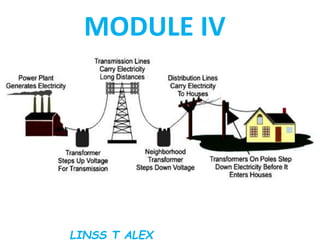
  • 21. Traditional Practices in Power System Planning Traditional electric power systems are designed on the premise of power production in central generating stations and its delivery to the points of end use via transmission and distribution systems. The role of generating stations is clear—they produce electric power or, more precisely, convert energy from another source into electric energy.  The roles of transmission and distribution systems are more interrelated; both are concerned with power delivery .
  • 22. The role of transmission systems is to interconnect many generators and loads across entire regions and over state and country boundaries. Transmission systems enable the transfer of power over long distances, and thus facilitate economic and system benefits. They are designed and operated to optimize the use of the generation portfolio. They make it possible to supply loads from the most economical sources of power and to operate generating stations flexibly, allowing for optimization of their maintenance schedules and improved overall system reliability.
  • 23. Conversely, distribution systems are the part of electric delivery infrastructure that brings the power to the loads; they “touch” the load.  The interface point between the transmission and a distribution system is a (distribution) substation. A distribution system usually includes the substation and all other infrastructure between the substation and the load, including primary circuits (feeders and laterals), service transformers, secondary circuits, and customers’ meters. Generally, distribution systems are designed for unidirectional power flow from the substation to end-use loads, and it is implicitly assumed that there is a sufficient supply of power from the transmission system (at the high-voltage side of the substation).
  • 24. Traditional system planning activities follow this functional division, and commonly are segregated into generation planning, transmission planning, and distribution planning.
  • 25. Generation Planning Load Forecasting In the short term, load can be forecast with great accuracy, and this is performed daily to determine generation units’ commitment. Load forecasting for the purpose of generation planning, however, requires a substantially longer time horizon, because system expansion projects require long lead times, often between 2 and 10 years. The outputs from a load forecast are a forecast of annual energy sales (in kilowatt-hours), and the annual peak demand (in kilowatts). There are two widely used methods in energy sales forecasting, econometric regression analysis, and end- use electricity models.
  • 26. The usefulness of each method depends on data availability, customer segmentation, and the degree of detail required. End-use electricity models are physical, engineering based methods that often are used in forecasting the residential load, and sometimes for commercial and industrial loads. Forecasting the peak demand is done based on forecasted energy sales by multiplying forecasted energy with an empirically determined load factor coefficient. Peak load is extremely sensitive to weather, and both the historic data and the forecast must be adjusted consistently to normalize them relative to the weather. Peak load forecasting is important because it directly influences the required generation capacity—on every day of the year there must be enough available generation to feed the peak load.
  • 27. Relationship Between Capacity Reserves and Reliability  Generating stations require regular maintenance, which means that during some periods of the year they are not available to serve the load.  The stations also can be out of service due to unforeseen equipment failures; these outages, called forced outages, also contribute to reduced availability.  Assuming that maintenance requirements are known, and that forced outages can be characterized by probability, a natural question arising is, what is the appropriate capacity of generation for a given load forecast.  Appropriate in this context is directly tied to reliability of service, and it then follows that we need to find a mapping between capacity and service reliability or, more precisely, between capacity margins and service reliability.
  • 28.  Capacity margin is a better measure of reliability because it represents the difference between capacity and peak load (capacity alone is meaningless).  Required capacity reserves commonly are determined using a probabilistic approach that examines the probabilities of simultaneous outages of generating units and compares the resulting remaining capacity with the peak system load.  A number of days per year with capacity shortages thus can be determined and this measure, termed loss-of-load probability (LOLP) index, provides a consistent and sensitive measure of generation system reliability.  To determine LOLP index, both scheduled and forced outages are evaluated.
  • 29.  Scheduled outages are representative of the downtime required for regular maintenance, and these outages are scheduled deterministically to avoid periods of high peak load.  The forced outages are determined probabilistically, and the LOLP index is computed based on a large number of probabilistic experiments.  Using a probabilistic method is advantageous in implementation as it allows for convenient inclusion of other factors, such as transmission limitations between interconnected systems, and for simulation of a large number of units.  LOLP calculations commonly are performed for an entire interconnected system, as this properly evaluates the benefits of shared generation reserves.
  • 30.  A common target value for the LOLP index is 1 day per 10 years, which is equivalent to 0.1 day per year.  Therefore, given a system and the outage characteristics of the units, planners can determine whether it satisfies the desired LOLP index.  The converse however is not true; it is not possible to go from a desired LOLP to the optimal system expansion.  Planning the expansion to meet the desired LOLP (i.e., reliability), and do so at a minimal cost.
  • 31. Capacity Resource Planning  The question of what type of generating station (hydroelectric, nuclear, coal, gas turbine, or other) would be the most economical addition to the system is answered by combining a production cost analysis with an investment cost analysis.  The evaluation begins by preparing a set of expansion scenarios.  An expansion scenario includes additions of multiple units and the planners are required to hypothesize the type and the number of units that should be considered.  The scenarios then are evaluated one at a time, beginning with a multiyear reliability simulation to determine the LOLP index for each year of study.  If the reliability requirements are not met they often can be improved either by advancing the installation dates of some units, or by delaying retirement dates of others.
  • 32.  The corrected scenario then is reevaluated and possibly refined again until the reliability targets are met.  Note that these iterations eventually might fail to give acceptable reliability; this possibility should not be regarded as a deficiency of the process, but rather as an indication of an inadequate scenario.  If found, then inadequate scenarios are removed, and the process continues to consider the scenarios that meet the reliability target.  The next step in evaluating scenarios is to run a multiyear production simulation for each.  Production simulation determines the dispatch of every unit and its associated running costs—such as costs of fuel and maintenance.
  • 33.  Cumulative fuel costs of a unit depend on the unit’s dispatch—how often it runs and at what operating point.  Production simulation determines the dispatch and associated costs for all units in the system, and these costs are recorded for each year of the multiyear study.  This is shown symbolically as the data output to the right of the “multiyear production simulation” processing block.  Multiple data outputs are shown (stacked)—each corresponds to one expansion scenario.
  • 34.
  • 35. Transmission Planning • A transmission system makes it possible to supply loads from the most economical sources of power, and operate generating stations flexibly and thus improve overall system reliability. • Transmission planning therefore ensures that the transmission infrastructure can deliver power from the generators to the loads, and that all the equipment will remain within its operating limits in both normal operation and during system contingencies. • Contingencies in this context mean unexpected failures of any system element; for example a generator or a transmission line could have an unexpected outage, which would force the remainder of the system to transition to a new operating point.
  • 36. • Studying these transitions and ensuring that a stable operating point can be reached after any contingency is an essential part of transmission system planning. • Transmission system planning is closely interrelated with generation planning. • To understand this, it is helpful to note that power flows through a transmission system are a direct result of generation dispatch; a transmission system itself has very limited ability to control the line flows. • The power flow through a transmission system, it is necessary to know the corresponding generation dispatch; to determine the (optimal) generation dispatch, however, the parameters and flow limitations imposed by the transmission system must be known.
  • 37. • This “loop” is not always easy to resolve, and it might require complicated iterations between the two planning processes. Generation dispatch and the associated power flows change many times throughout the day and often follow rather different seasonal schedules. • The transmission system therefore can exist in many diverse operating states, and in each one it must be able to cope with the loss of any single element.
  • 38. • Transmission planning is tasked with evaluation of all these operating states and their associated contingencies and determining the stability of the system for the set of worst- case conditions. • Selecting a set of worst-case conditions is not straightforward and it is most often based on historical system performance and planners’ experience and judgment
  • 39. Rotor-Angle Stability • Rotor-angle stability is the ability of generators in the interconnected power system to remain synchronous after a system disturbance. • Traditionally the interface between the two is a generator and, under steady-state conditions, the electrical torque balances the mechanical torque that is driving the generator, so that the generator operates at a constant speed. • This balance can be disturbed at any time, leading to excursion of rotor angles and corresponding electromechanical oscillation. • Based on the type of disturbance, rotor-angle stability consideration can be further classified into small signal (or steady-state) stability, and large disturbance (or transient) stability.
  • 40. Small Signal Stability • Small signal stability refers to disturbances sufficiently small to warrant analysis by linearization of system equations around the operating point. Small signal stability is evaluated relative to the following physical phenomena: • Local modes—oscillations of a small group of machines (often in the same power station) relative to the power system • Inter-area modes—oscillations of a group of machines in one part of the system against another group of machines in another part of the system • Control modes—oscillations brought on by control interactions between system elements • Torsional modes—commonly associated with the interaction between a turbinegenerator shaft system and another system element, usually a line compensated by a series capacitor.
  • 41. Transient Stability • Transient stability deals with large disturbances and evaluates the ability of a system to maintain synchronism when subjected to a severe disturbance. • The resulting system response involves large excursions of generator rotor angles and the governing equations are nonlinear. The analysis typically is done by time domain simulations that include models of generator prime mover dynamics, excitation dynamics, and load dynamics.
  • 42. Voltage Stability • The essential cause of voltage instability is the voltage drop that occurs on the inductive reactance associated with the transmission network. In a heavily loaded system, voltage to the load reduces due to these voltage drops, and this increases current draw from the load, so the positive feedback leading to instability can be established easily. • The situation becomes progressively worse as some of the generators reach the reactive power capability limit (essentially the current limit), and the end result is voltage collapse at the load. • These events can be precipitated both by loss of generation and loss of transmission, and typically are evaluated by time domain simulations that include voltage-sensitive models of load, and the responses of generator excitation systems.
  • 43. Frequency Stability • Frequency stability studies determine the system’s ability to maintain steady frequency within a nominal range following a severe system disturbance that results in a significant imbalance between generation and load. • A system’s response to frequency stability includes block load shedding and other special protection schemes that typically are not considered in simulations that deal with rotor stability and voltage stability.
  • 44. Distribution System Planning • Distribution systems are the part of electricity delivery infrastructure that serves the load. • Traditionally distribution systems are optimized for the lowest cost that meets the desired reliability of service, and reliability is carefully tracked and reported. • This has profound implications on planning practices, because reliability is explicitly engineered into the system, and is used as an important metric in evaluating planning options.
  • 45. Load Forecasting • Load forecasting is critically important in distribution system planning and, arguably, distribution utilities are in the best position to make accurate load forecasts. • Distribution utilities directly meter their customers and therefore have access to the exact data needed. • They also are notified of development projects in their service territory early in the process and, through that mechanism, have a good insight into prospective load growth. • Given their proximity to the load, distribution utilities have the necessary data to successfully employ end-use electricity models.
  • 46. Planning for Reliability • Reliability in distribution planning is defined and evaluated quite differently compared with reliability evaluation in generation planning. • Evaluation of reliability is not absolute (as is the case in generation planning via computing of an LOLP index) but incremental. Reinforcement and planning options are considered relative to their impact on reliability. • One example of such a process, termed Cost-Effective Reliability Improvement (CERI) is described in Willis (2004). It begins with known baseline reliability, and then evaluates many possible improvement options relative to their impact on customer reliability. • Options are ranked based on their cost-benefit ratio, and the best ones are implemented.
  • 47. Distribution System Engineering • Of course, there is much more to distribution system design than load forecasting and planning for reliability. • Important design choices include distribution substation siting and sizing and feeder layout (including choosing a number and placement of reclosers and sectionalizers). • Additionally, studies that address feeder voltage control, feeder protection, and motor starting also are required.
  • 48. Optimum electric power generating unit GENERATING UNIT CATEGORIES Coal fired steam cycle Oil fired steam cycle Natural gas fired steam cycle Nuclear Oil fired combustion engine Natural gas fired combustion turbine Oil fired combined cycle Natural gas fired combined cycle Hydro-electric Geothermal steam
  • 49. Steps to Determine the Optimum New Electric-Power Generating Unit 1- Identify all possible energy sources ( fuel) and electric generation system 2-Eliminate alternatives that fail to meet system commercial-availability criteria 3-Step 3 Eliminate alternatives that fail to meet energy source (fuel) commercial-availability criteria. 4-Eliminate alternatives that fail to meet other functional or site-specific criteria 5-eliminate alternatives that are always more costly than other feasible alternatives
  • 50. A-Calculate the appropriate annual fixed-charge rate. B-Calculate fuel costs on a dollars per million Btu basis. C-Calculate the average net generation unit heat rates. D-Construct screening curves for each system. E-Use screening-curve results to choose those alternatives to be evaluated further
  • 51. F-Construct screening curves for feasible renewable and alternative energy sources and generation systems and compare with alternatives in Step 5E 6-Determine coincident maximum predicted annual loads over the entire planning period. 7-Determine the required planning reserve margin 8-Evaluate the advantages and disadvantages of smaller and larger generation-unit and plant ratings
  • 52. A-Consider the economy-of-scale savings associated with larger unit and plant ratings. B-Consider the operational difficulties associated with unit ratings that are too large. C-Take into account the range of ratings commercially available for each generation-system type. D-Consider the possibility of jointly owned units. E-Consider the forecast load growth. F-Determine the largest unit and plant ratings that can be used in generation expansion plans
  • 53. 9-Develop alternative generation expansion plans. 10-Compare generation expansion plans on a consistent basis. 11-Determine the optimum generation expansion plan by using an iterative process. 12-Use the optimum generation expansion plan to determine the next new generation units or plants to be installed. 13-Determine the generator ratings for the new generation units to be installed 14-Determine the optimum plant design.
  • 54. 15-Evaluate trade off of annual operation and maintenance costs vs. installed capital costs. 16-Evaluate tradeoffs of thermal efficiency vs. capital costs and/or operation and maintenance costs. 17-Evaluate trade off of unit availability (reliability) and installed capital costs and/or operation and maintenance costs. 18-Evaluate trade off of unit rating vs. installed capital costs.