Downloaded 751 times


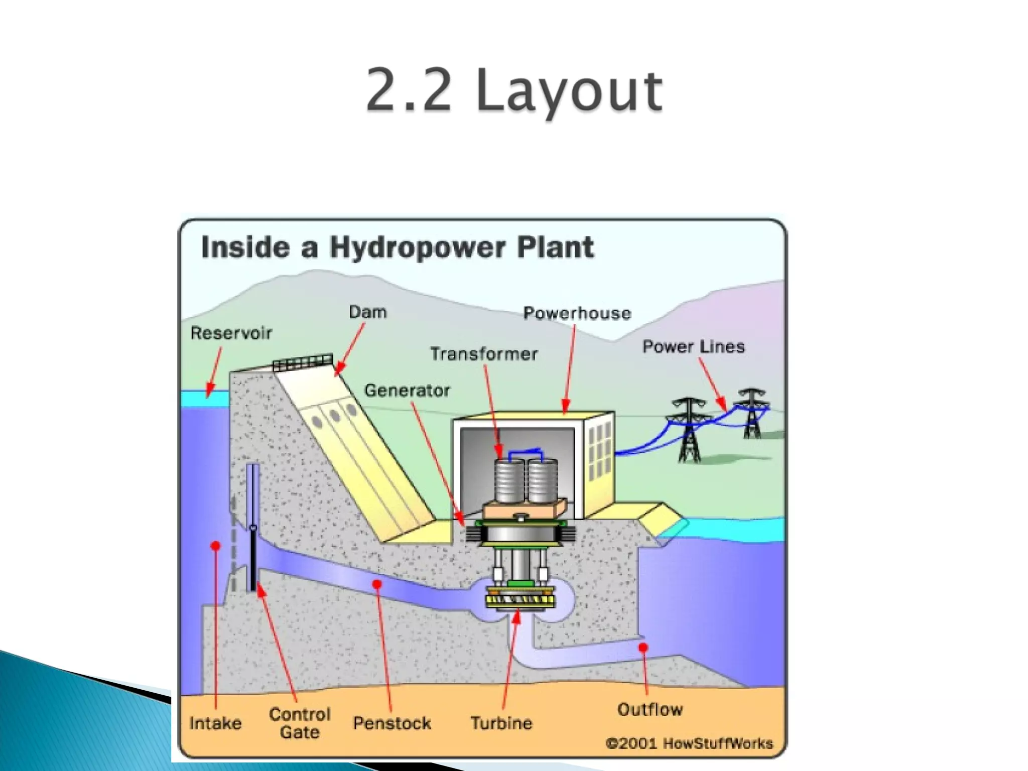
![ Hydroelectric power captures the energy released
from falling water.
Potential Energy Kinetic energy Electrical
Energy
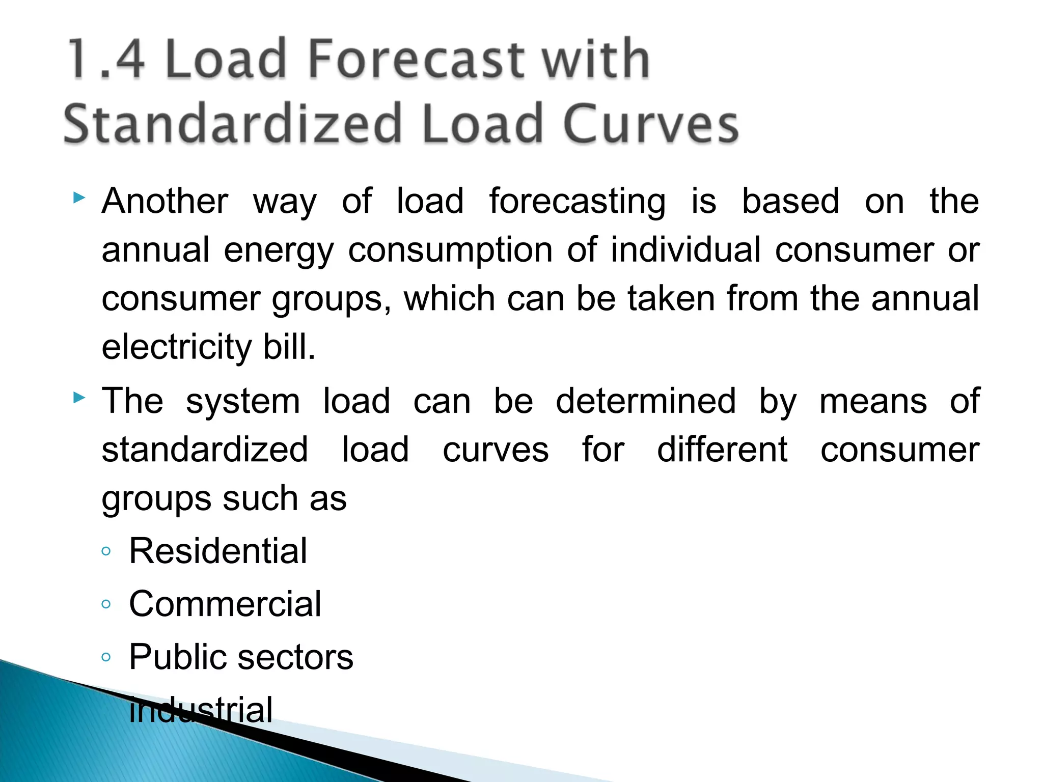
Hydroelectric power plants are categorized as
◦ Micro hydropower plants [<100 kW)
◦ Mini Hydropower Plants [100 kW – 1 MW]
◦ Small Hydropower Plants [1 MW – 30 MW]
◦ Large Hydropower Plants [>30 MW]
In Ethiopia, more than 96% of the electricity is hydro.](https://image.slidesharecdn.com/powersystemplanningoperationeceg-4410-130607134359-phpapp01/75/Power-system-planning-operation-eceg-4410-26-2048.jpg)


![Power system planning & operation [eceg 4410]](https://image.slidesharecdn.com/powersystemplanningoperationeceg-4410-130607134359-phpapp01/75/Power-system-planning-operation-eceg-4410-151-2048.jpg)
![Power system planning & operation [eceg 4410]](https://image.slidesharecdn.com/powersystemplanningoperationeceg-4410-130607134359-phpapp01/75/Power-system-planning-operation-eceg-4410-152-2048.jpg)
![Power system planning & operation [eceg 4410]](https://image.slidesharecdn.com/powersystemplanningoperationeceg-4410-130607134359-phpapp01/75/Power-system-planning-operation-eceg-4410-153-2048.jpg)

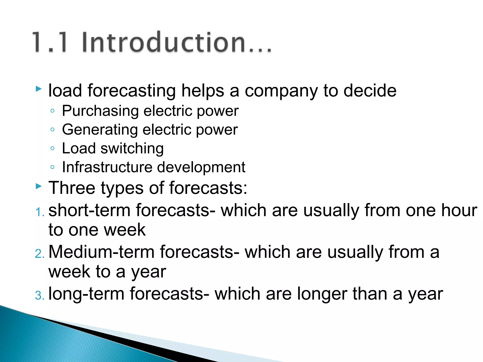
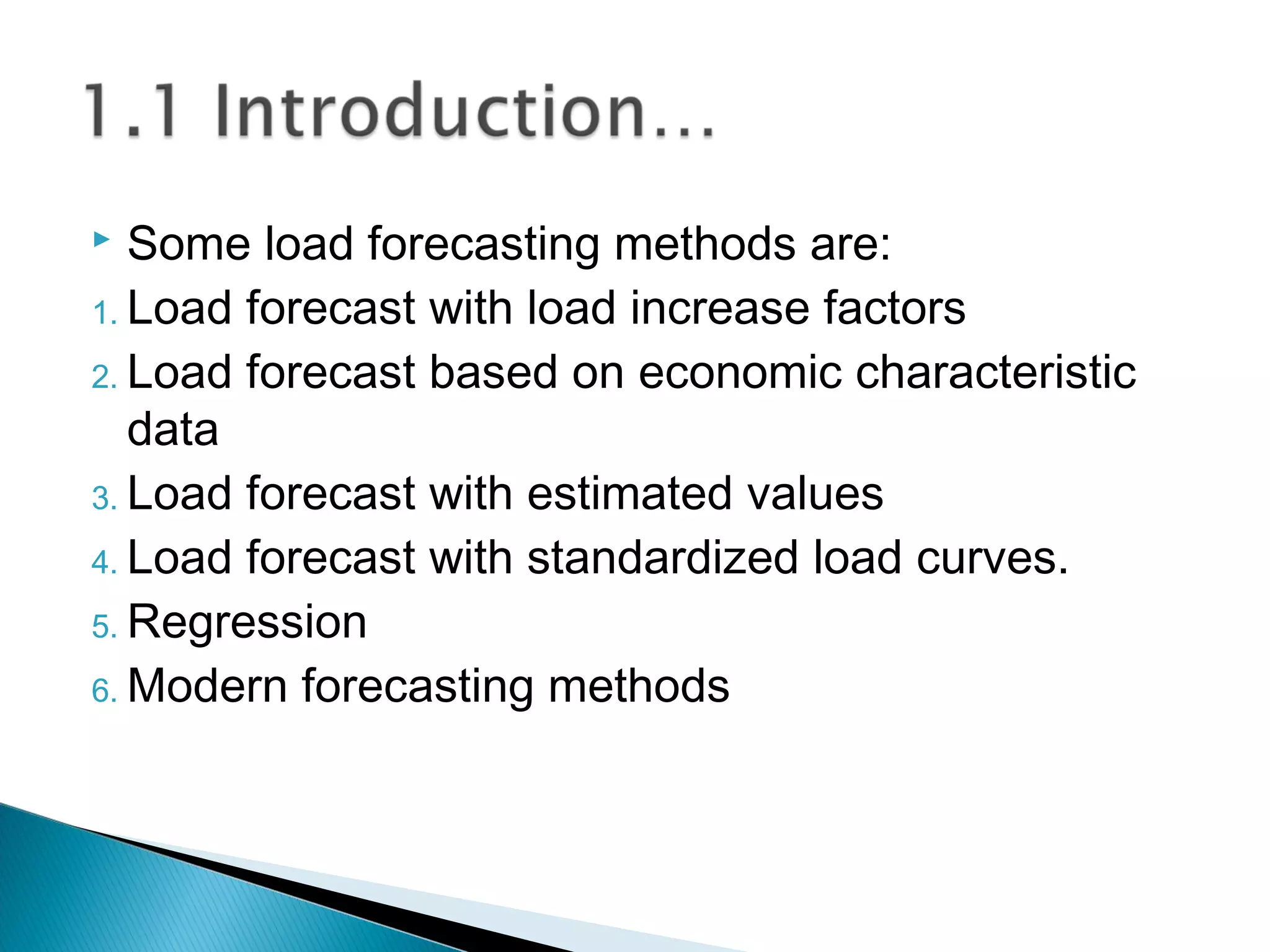
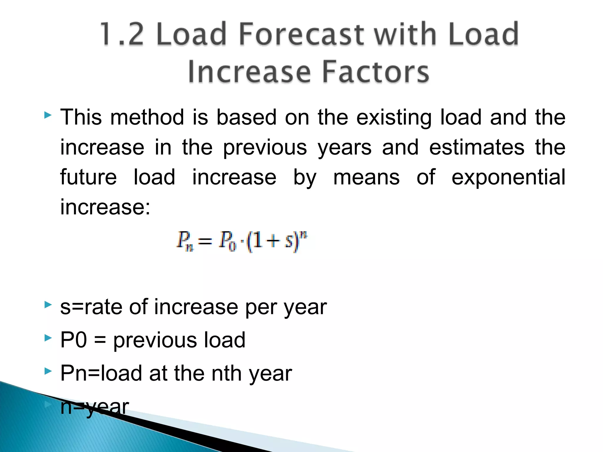
The document discusses power load forecasting and substation planning. It explains that accurate load forecasting is important for power system planning and operation. Several load forecasting methods are described, including those based on historical load data, economic factors, and standardized load curves. Load forecasts can be short, medium, or long-term. The document also discusses factors to consider in substation planning and design, such as location, equipment requirements, and configuration. Feasibility studies are important for assessing potential hydroelectric and substation projects.