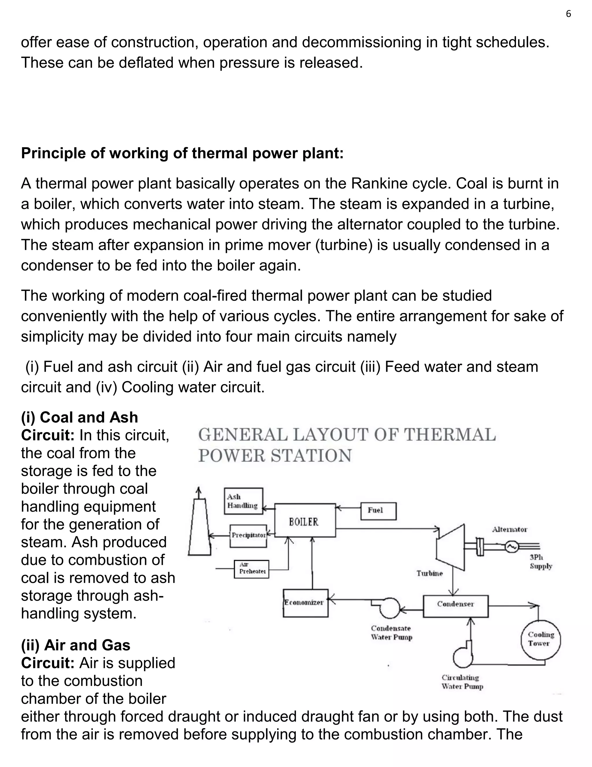
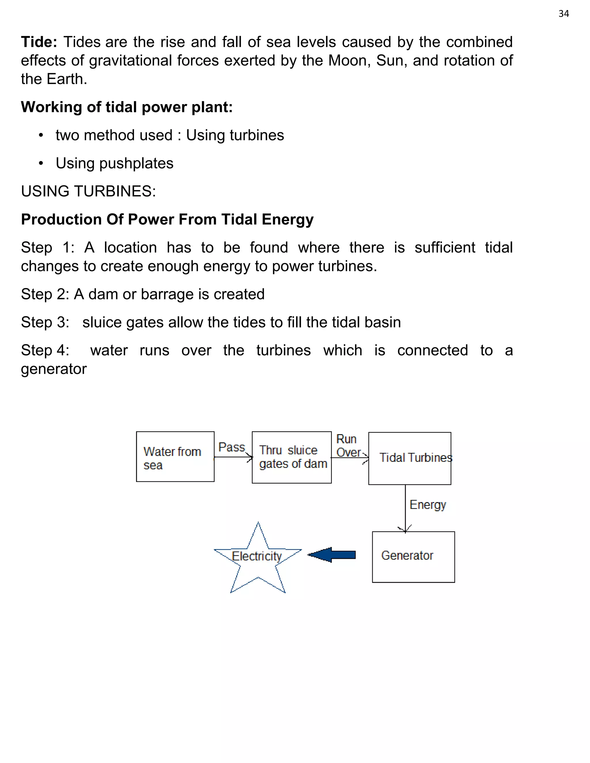
The document discusses various sources of energy and hydroelectric power generation. It provides details on the different types of dams used in hydroelectric power stations including their structure and functions. The summary is:
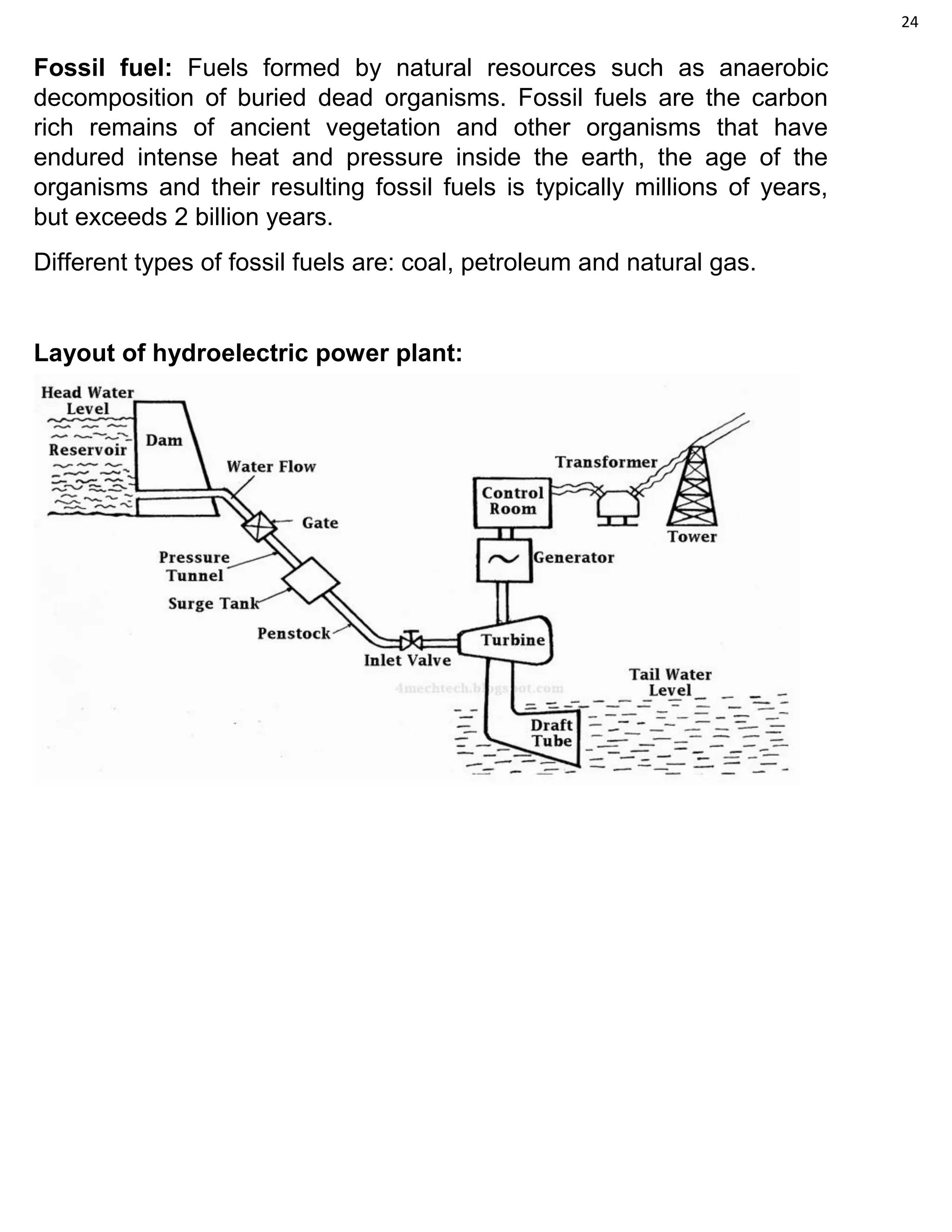
The document discusses various sources of energy like the sun, wind, water, fuels, and nuclear energy. It also describes the different types of dams used in hydroelectric power stations based on their functions like storage, diversion, and debris control. Various dam structures are outlined, including gravity, earthfill, rockfill, arch, buttress, and other less common designs. The principles of hydroelectric power generation are explained where potential energy of water is converted to rotational energy by turbines to power generators. [/SUMMARY]