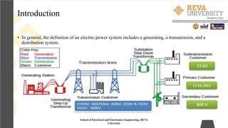
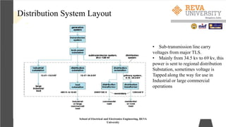
SlideShare a Scribd company logo
1 of 52
Electrical Distribution System
Name of the Faculty : Adithya Ballaji
School of Electrical and Electronics Engineering
Unit 1: Distribution System Planning and Design
School of Electrical and Electronics Engineering, REVA
University
Syllabus
• Introduction, Factors affecting system planning, present planning
techniques, planning models, Sub-transmission and substation design.
Sub-transmission networks configurations, Substation bus schemes,
Distribution substations ratings, Service areas calculations, and
Substation application curves, future trends in planning, systems
approach, and Distribution automation.
School of Electrical and Electronics Engineering, REVA
University
Introduction
• In general, the definition of an electric power system includes a generating, a transmission, and a
distribution system.
School of Electrical and Electronics Engineering, REVA
University
Distribution System Layout
School of Electrical and Electronics Engineering, REVA
University
• Sub-transmission line carry
voltages from major TLS.
• Mainly from 34.5 kv to 69 kv, this
power is sent to regional distribution
Substation, sometimes voltage is
Tapped along the way for use in
Industrial or large commercial
operations
SLD of GTD
School of Electrical and Electronics Engineering, REVA
University
Distribution System
“The part of power system which distributes electrical power for local use is known as
DISTRIBUTION SYSTEM.”
• This system is the electrical system between the substation fed by the transmission system and
consumer meter.
• Distribution line generally consist of
1. Feeders
2. Distributers
3. Service mains
School of Electrical and Electronics Engineering, REVA
University
Feeders
• A Feeder is conductor which connects the substation to the area where power is
to be distributed .
• Feeder are used to feed the electrical power from the generating station to the substation
• No tapings are taken from the feeder
• So the current in it remains the same throughout
• Main consideration in the design of feeder is the Current carrying capacity.
Distributer
• A distributer is a conductor from which tapings are taken from pole mounted transformer to the
consumer
• The current through a distributer is not constant because tapings are taken at various places along
its length
• Voltage drop is main consideration
• Limit of variation is 6% of rated at consumer
School of Electrical and Electronics Engineering, REVA
University
Service mains
• A service mains is a generally a small cable which connects the distributer to the
consumer ‘s meter.
The connecting links between the distributor and the consumer terminals.
School of Electrical and Electronics Engineering, REVA
University
Distribution system
Distribution system is a part of power system, existing between distribution substations and
consumers.
It is further classified on the basis of voltage
Primary distribution system- 11 KV or 6.6 KV or 3.3 KV
Secondary distribution system- 415 V or 230 V
Classification Of Distribution System: It can be classified under different considerations as; 1. Type
Of Current: a) AC Distribution System b) DC Distribution System
2. Type Of Construction: a) Overhead System b) Underground System
3. Type Of Service: a) General Lighting & Power b) Industrial Power c) Railway d) Streetlight etc
4. Number Of Wires: a) Two Wire b) Three Wire c) Four Wire
5. Scheme Of Connection: a) Radial Distribution System b) Ring or Loop Distribution System c)
Interconnected Distribution System
School of Electrical and Electronics Engineering, REVA
University
AC distribution
• AC distribution system is the electrical system between the step-down
substation fed by the transmission system and the consumers’ meters.
• The AC distribution system is classified into
• Primary distribution system
• Secondary distribution system.
• Why Study of Electrical Distribution System is Necessary?
• In recent years the investment trends show that the percentage of electrical plants in service by the
production, i.e, GTD major investment as been in generation followed closely in second by
distribution.
• The major expenses for O & M has been in production sector followed by distribution sector
• The economic importance of the distribution system is very high, and the amount of investment
involved needs careful planning, design, construction and operation
School of Electrical and Electronics Engineering, REVA
University
Distribution System Planning
Distribution System planning is essential to ensure that the growing demand for
electricity can be satisfied by addition of DS which are technically adequate and also
economical.
The objective of distribution system planning is to assure that the growing demand for electricity, in
terms of increasing growth rates and high load demand, can be satisfied in an optimum way by
additional distribution systems
School of Electrical and Electronics Engineering, REVA
University
First Distribution system planners must determine the load
magnitude and its geographic location. Then the DS must be
placed and sized in such a way as to serve the load at maximum efficiency,
being cost effectiveness by minimizing feeder losses and construction costs,
while considering the constraints of service reliability.
Factors Effecting DSP
School of Electrical and Electronics Engineering, REVA
University
Demand of ever increasing power capacity, Higher distribution voltages, automation
and special control are some of the parameter which effect the DSP.
In general the factors effecting may include scarcity in availability of land in urban areas,
ecological considerations and limitation on fuel choices, investment etc.
• Load Forecasting
• The load demand growth of geographic area is the most important factor which influences the expansion
Of DS.
• Thus the forecasting of load increase and the system reaction to these increases is the most important in
planning process.
• Load forecasting is done in two ways based on time, long range forecasting for 15-20 years and short
range for 5 years.
• These forecasting would predict the future loads in details and the final loads are predicted in kVA
Factors affecting DSP
School of Electrical and Electronics Engineering, REVA
University
Substation Expansion
School of Electrical and Electronics Engineering, REVA
University
• The planner makes the decision based on tangible and intangible information.
• For example the forecasted load, load demand and load growth may require a substation expansion
or new substation.
Substation site selection
• The distance from the load centers and from the existing sub-transmission lines as well as other
limitations, such as availability of land, its cost, and land use regulations, is important.
• The substation siting process can be described as a screening procedure through which all possible
locations for a site are passed
Substation Site Selection
School of Electrical and Electronics Engineering, REVA
University
• Service region is the area
Under Evaluation
• Candidate areas are divided
Into three groups:
1. Sites which are unsuitable
2. Sites which are initially
selected but rejected after
panning process.
3. Sites which needs to be
studied in detail
Other Factors
School of Electrical and Electronics Engineering, REVA
University
• Once the loads are predicted and assigned, then other factors are considered
like, primary voltage selection, feeder route selection, number of feeders,
conductor size selection and total cost are taken into account for final
planning process.
Present Planning techniques
School of Electrical and Electronics Engineering, REVA
University
• Computer based : many electric distribution system planners in the industry utilize computer
programs
• Such as load flow programs, radial or loop load flow programs, short-circuit and fault-current
calculation programs, voltage drop calculation programs, and total system impedance calculation
programs, as well as other tools such as load forecasting, voltage regulation, regulator setting,
capacitor planning, reliability, and optimal siting and sizing algorithms.
• The computers do perform calculations more expeditiously than other methods and free the
distribution engineer from detailed work. The engineer can then spend time reviewing results of the
calculations, rather than actually making them.
School of Electrical and Electronics Engineering, REVA
University
Typical Distribution System
Planning Process
Distribution System Planning Models
School of Electrical and Electronics Engineering, REVA
University
• In general, distribution system planning has a complex procedure due to a
large number of variables involved and mathematical requirements.
• Therefore, mathematical models are developed to represent the system and can be employed by
distribution system planners to investigate and determine optimum expansion patterns or
alternatives by selecting the following models:
1. Optimum substation locations
2. Optimum substation expansions
3. Optimum substation transformer sizes
4. Optimum load transfers between substations and demand centers
5. Optimum feeder routes and sizes to supply the given loads subject to numerous constraints to
minimize the present worth of the total costs involved
Sub-transmission System
School of Electrical and Electronics Engineering, REVA
University
• The sub-transmission system is defined as the circuits which deliver energy from the transmission
system to the primary distribution system.
• But usually the sub-transmission system are supplied from the transmission sub-stations and still
referred to as sub-transmission.
• Earlier many of the sub-transmission system were the transmission lines, but sue the increase in the
load growth and demand for more power led to the reduction of voltage from 220kV to 33kV
which are found in the sub-transmission lines.
• Mainly the distribution system are considered to be consisting four main components : Its sub-
transmission system, the substation itself, the feeder system and the consumers.
• The distribution substation reduces the voltage to the lower primary voltage in the range of 22 to
11kV for local distribution.
• The local transformer reduces the voltages to 430/415V or 230/240V with a variation of +/- 6
percent at the consumer end.
Sub-transmission network configuration
School of Electrical and Electronics Engineering, REVA
University
• Radial distribution system
Sub-transmission network configuration
School of Electrical and Electronics Engineering, REVA
University
• Radial distribution system
• This system is used only when substation or generating station is located at the center of the
consumers.
• In this system, different feeders radiate from a substation or a generating station and feed the
distributors at one end.
• Thus, the main characteristic of a radial distribution system is that the power flow is in only one
direction.
• Although this system is simplest and least expensive, it is not highly reliable.
• A major drawback of a radial distribution system is, a fault in the feeder will result in supply
failure to associated consumers as there won't be any alternative feeder to feed distributors.
Sub-transmission network configuration
School of Electrical and Electronics Engineering, REVA
University
• Ring main distribution system
Sub-transmission network configuration
School of Electrical and Electronics Engineering, REVA
University
• Ring main distribution system
• Here, each distribution transformer is fed with two feeders but in different paths.
• The feeders in this system form a loop which starts from the substation bus-bars, runs through the
load area feeding distribution transformers and returns to the substation bus-bars.
• Ring main distribution system is the most preferred due to its following advantages.
Advantages of ring main distribution system
• There are fewer voltage fluctuations at consumer's terminal.
• The system is very reliable as each distribution transformer is fed with two feeders. That means, in
the event of a fault in any section of the feeder, the continuity of the supply is ensured from the
alternative path.
Sub-transmission network configuration
School of Electrical and Electronics Engineering, REVA
University
• Interconnected distribution system
Sub-transmission network configuration
School of Electrical and Electronics Engineering, REVA
University
• Interconnected distribution system
• When a ring main feeder is energized by two or more substations or generating stations, it is called
as an interconnected distribution system.
• This system ensures reliability in an event of transmission failure.
• Also, any area fed from one generating stations during peak load hours can be fed from the other
generating station or substation for meeting power requirements from increased load.
Sub-transmission network configuration
School of Electrical and Electronics Engineering, REVA
University
• Parallel feeders distribution system
Sub-transmission network configuration
School of Electrical and Electronics Engineering, REVA
University
• Parallel feeders distribution system
• The disadvantage of a radial system can be minimized by introducing parallel feeders.
• The initial cost of this system is much more as the number of feeders is doubled.
• Such system may be used where reliability of the supply is important or for load sharing where the
load is higher
Substation Bus Schemes
School of Electrical and Electronics Engineering, REVA
University
• The electrical substation is a junction point where two or more transmission lines terminate.
• In reality, most EHV and HV substations can be the point where more than half a dozen of lines
terminate.
• In many large transmission substations, the total numbers of lines terminating exceeds one or two
dozen.
• A substation bus scheme is the arrangement of overhead bus bar and associated switching
equipment (circuit breakers and isolators) in a substation.
• The operational flexibility and reliability of the substation greatly depends upon the bus scheme.
• Types of bus scheme:
• Single Bus
• Main Bus and Transfer Bus
• Double Bus and Double Breaker
• Ring or Mesh Bus
• Break and Half
Substation Bus Schemes
School of Electrical and Electronics Engineering, REVA
University
Single Bus Configuration
Substation Bus Schemes
School of Electrical and Electronics Engineering, REVA
University
• As the name implies, the single bus substation configuration consists of all circuits connected to a
main bus.
• A fault on the bus or between the bus and circuit breaker will result in an outage of the entire bus
or substation.
• Failure of a single circuit breaker will also result in an outage of the entire bus.
• Maintenance of any circuit breaker requires shutdown of the corresponding circuit/line and
maintenance of the bus requires a complete shutdown of the bus.
• A bypass switch across the breaker should be used for maintenance of the corresponding breaker.
Circuit protection is disabled in this case.
Substation Bus Schemes
School of Electrical and Electronics Engineering, REVA
University
Main and Transfer Bus Configuration
Substation Bus Schemes
School of Electrical and Electronics Engineering, REVA
University
• In this arrangement one or more busses is added to the single bus substation scheme.
• One or more circuit breakers may be used in this arrangement to make connections between the
main and transfer bus.
• For maintenance of a circuit breaker, the transfer bus is energized by closing the isolator switches
to the transfer bus, then the circuit breaker to be maintained is opened and isolated on both sides.
Substation Bus Schemes
School of Electrical and Electronics Engineering, REVA
University
Double Bus Double Breaker
Substation Bus Schemes
School of Electrical and Electronics Engineering, REVA
University
• This configuration utilizes two buses and two breakers per circuit.
• Both buses are normally energized and any circuit can be removed for maintenance without an
outage on the corresponding circuit.
• Failure of one of the two buses will not interrupt a circuit because all of the circuits can be fed
from the remaining bus and isolating the failed bus.
• Substations with the double bus double breaker arrangement require twice the equipment as the
single bus scheme but are highly reliable.
• Load balancing between buses can be achieved by shifting circuits from one bus to the other.
• This scheme is typically found in EHV transmission substations or generating stations.
Substation Bus Schemes
School of Electrical and Electronics Engineering, REVA
University
Ring Bus Configuration
Substation Bus Schemes
School of Electrical and Electronics Engineering, REVA
University
• In the ring bus configuration, as the name implies, the circuit breakers are connected to form a ring,
with isolators on both sides of each breaker.
• Each circuit is fed from both sides.
• This scheme has good operational flexibility and high reliability, any of the circuit breakers can be
opened and isolated for maintenance without interruption of service.
Substation Bus Schemes
School of Electrical and Electronics Engineering, REVA
University
Breaker and Half Configuration
Substation Bus Schemes
School of Electrical and Electronics Engineering, REVA
University
• When expansion of the substation is required to accommodate more circuits, can easily be
expanded to the One and Half breaker configuration.
• This configuration uses two main buses, both of which are normally energized with three breakers
connected between the buses.
• In this bus configuration, three breakers are required for every two circuits - hence the "one and
half" name.
• Think of it as, to control one circuit requires one full and a half breaker.
• The middle breaker is shared by both circuits, similar to a ring bus scheme where each circuit is fed
from both sides.
• Any circuit breaker can be isolated and removed for maintenance purposes without interrupting
supply to any of the other circuits.
• Additionally, one of the two main busses can be removed for maintenance without interruption of
service to any of the other circuits.
Substation Bus Schemes - Comparison
School of Electrical and Electronics Engineering, REVA
University
Type of Bus Scheme Advantages Disadvantages
Single bus 1. Lowest cost 1. Failure of bus or any circuit
breaker results in shutdown of
entire substation
2. Difficult to do any
maintenance
3. Bus cannot be extended
without completely de-
energizing substation
4. Can be used only where loads
can be interrupted or have other
supply arrangements
Substation Bus Schemes - Comparison
School of Electrical and Electronics Engineering, REVA
University
Type of Bus Scheme Advantages Disadvantages
Main-and-transfer 1. Low initial cost.
2. Any breaker can be taken out
of service for maintenance.
1. Requires one extra breaker
for the bus tie.
2. Switching is somewhat
complicated when maintaining a
breaker.
Substation Bus Schemes - Comparison
School of Electrical and Electronics Engineering, REVA
University
Type of Bus Scheme Advantages Disadvantages
Double bus–double breaker 1. Each circuit has two
dedicated breakers
2. Has flexibility in permitting
feeder circuits to be connected
to either bus
3. Any breaker can be taken out
of service for maintenance
4. High reliability
1. Most expensive
2. Would lose half the circuits
for breaker failure if circuits are
not connected to both buses
Substation Bus Schemes - Comparison
School of Electrical and Electronics Engineering, REVA
University
Type of Bus Scheme Advantages Disadvantages
Ring bus 1. Low initial cost
2. Flexible operation for breaker
maintenance
3. Any breaker can be removed
for maintenance without
interrupting load
4. Requires only one breaker per
circuit
5. Does not use main bus
6. Each circuit is fed by two
breakers
1. If a fault occurs during a
breaker maintenance period, the
ring can be separated into two
sections
2. Breaker failure during a fault
on one of the circuits causes
loss of one additional circuit
Substation Bus Schemes - Comparison
School of Electrical and Electronics Engineering, REVA
University
Type of Bus Scheme Advantages Disadvantages
Breaker-and-a-half l. Most flexible operation
2. High reliability
3. Breaker failure of bus side
breakers removes only one
circuit from service
4. Either main bus can be taken
out of service at any time for
maintenance
5. Bus failure does not remove
any feeder circuits from service
1. 1½ breakers per circuit
2. High Cost
Rating of Distribution Substation
School of Electrical and Electronics Engineering, REVA
University
• Substations receive Electric energy from Generating stations or other Substations via long
Transmission lines with 110/230/400 kV system voltage.
• Substations are equipped with Transformers to step down the voltage to 11/33/66 kV to feed HT
distribution lines.
• Which is expressed in kilovolt-amperes (kVA) or megavolts- amperes (MVA), and indicates the
amount of power that can be transferred through the transformer. Distribution substation
transformers are typically in the range of 3 kVA to 25 MVA.
• The MVA capacity of these Transformers is called as the rating of the Substation.
Bus-bars or Buses
School of Electrical and Electronics Engineering, REVA
University
• Bus-bars (also called buses) can be found throughout the entire power system, from generation to
industrial plants to electrical distribution boards. Bus-bars are used to carry large current and to
distribute current to multiple circuits within switchgear or equipment.
• Plug-in devices with circuit breakers or fusible switches may be
installed and wired.
• Originally, bus-bars consisted of uncovered copper conductors
supported on insulators, such as porcelain, mounted within a
non-ventilated steel housing. This type of construction was
adequate for current ratings of 225–600 A.
Bus-bars or Buses
School of Electrical and Electronics Engineering, REVA
University
• The bus-bars were also covered with insulation for safety and to permit closer spacing of bars of
opposite polarity in order to achieve lower reactance and voltage drop.
Central Role of Computer in DSP – System Approach
School of Electrical and Electronics Engineering, REVA
University
• Distribution system planners use computer based tools to perform the tedious calculations
necessary for system analysis.
• It has only been in the past few years that technology has provided the means for planners to truly
take a system approach to the total design and analysis.
• The system approach using computer tools starts by examining the types of information
required and its sources.
• The methodology used is that the information generated using the tool which are actually final
decisions and information are passed from one stage of the design process to another.
• It is thus noted that the human engineer must evaluate the information generated and add his or
her input. Finally, the results must be displayed for use and stored for later reference.
• The system approach seeks to automate as much of the process as possible, ensuring in the process
that the various transformations of information are made as efficiently as possible
Central Role of Computer in DSP – System Approach
• A database management system (DBMS) that stores, retrieves, and modifies various data on
distribution systems
• In addition to the database management program and the
network analysis programs.
• One such new tool is network editor.
• The features of the network editor may include network
objects, for example, feeder line sections, secondary line
sections, distribution transformers, or variable or fixed
capacitors, control mechanisms, and command functions.
Distribution System Automation
School of Electrical and Electronics Engineering, REVA
University
• The main purpose of an electric power system is to efficiently generate, transmit, and distribute
electric energy.
• The operations involved aims at geographically and functionally complex monitoring and control
systems.
• The supervisory control and data acquisition (SCADA) system involves generation and
transmission systems.
• The distribution automation and control (DAC) system oversees the distribution system,
including connected load.
• Automatic monitoring and control features have long been a part of the SCADA system.
• The term distribution automation has a very broad meaning, and additional applications are added
every day.
• To some people, it may mean a communication system at the distribution level that can control
customer load and can reduce peak-load generation through load management.
Distribution System Automation
School of Electrical and Electronics Engineering, REVA
University
• To others, the distribution automation may mean an unattended distribution substation that
could be considered attended through the use of an on-site microprocessor.
• The microprocessor, located at a distribution substation, can continuously monitor the system,
make operating decisions, issue commands, and report any change in status to the distribution
dispatch center, store it on-site for later use, or forget it, depending on the need of the utility
Thank You
School of Electrical and Electronics Engineering, REVA
University

More Related Content

What's hot

Chapter 3 Generation of high voltages and current
Chapter 3 Generation of high voltages and currentChapter 3 Generation of high voltages and current
Chapter 3 Generation of high voltages and currentmukund mukund.m
 
Flexible ac transmission system
Flexible ac transmission systemFlexible ac transmission system
Flexible ac transmission systemUday Wankar
 
Lab manual psd v sem experiment no 7
Lab manual psd v sem experiment no 7Lab manual psd v sem experiment no 7
Lab manual psd v sem experiment no 7Sachin Airan
 
Advanced Metering Infrastructure (AMI)
Advanced Metering Infrastructure (AMI)Advanced Metering Infrastructure (AMI)
Advanced Metering Infrastructure (AMI)Naveena Navi
 
Introduction to power system analysis
Introduction to power system analysisIntroduction to power system analysis
Introduction to power system analysisRevathi Subramaniam
 
Firing angle control
Firing angle controlFiring angle control
Firing angle controljawaharramaya
 
Extra high voltage long ac transmission lines
Extra high voltage long ac transmission linesExtra high voltage long ac transmission lines
Extra high voltage long ac transmission linesShivagee Raj
 
Multi terminal dc systems (mtdc)
Multi terminal dc systems (mtdc)Multi terminal dc systems (mtdc)
Multi terminal dc systems (mtdc)jawaharramaya
 
Deregulation in power industry
Deregulation in power industryDeregulation in power industry
Deregulation in power industryjerry patel
 
FACTS DEVICES AND POWER SYSTEM STABILITY ppt
FACTS DEVICES AND POWER SYSTEM STABILITY pptFACTS DEVICES AND POWER SYSTEM STABILITY ppt
FACTS DEVICES AND POWER SYSTEM STABILITY pptMamta Bagoria
 
POWER SYSTEM PLANNING
POWER SYSTEM PLANNINGPOWER SYSTEM PLANNING
POWER SYSTEM PLANNINGNishaDangi99
 
Electrical substations: 132 KV
Electrical substations: 132 KV Electrical substations: 132 KV
Electrical substations: 132 KV Girish Gupta
 
220KV Substation Training Report
220KV Substation Training Report220KV Substation Training Report
220KV Substation Training ReportSWAPNILKUMARGUPTA
 
Load Characteristics
Load CharacteristicsLoad Characteristics
Load CharacteristicsAmeen San
 
Power system interconnection presentation
Power system interconnection presentationPower system interconnection presentation
Power system interconnection presentationAneeque Qaiser
 
PPt on 220 kV substation
PPt on 220 kV substationPPt on 220 kV substation
PPt on 220 kV substationIshank Ranjan
 

What's hot (20)

Chapter 3 Generation of high voltages and current
Chapter 3 Generation of high voltages and currentChapter 3 Generation of high voltages and current
Chapter 3 Generation of high voltages and current
 
Power quality
Power qualityPower quality
Power quality
 
Flexible ac transmission system
Flexible ac transmission systemFlexible ac transmission system
Flexible ac transmission system
 
Lab manual psd v sem experiment no 7
Lab manual psd v sem experiment no 7Lab manual psd v sem experiment no 7
Lab manual psd v sem experiment no 7
 
Advanced Metering Infrastructure (AMI)
Advanced Metering Infrastructure (AMI)Advanced Metering Infrastructure (AMI)
Advanced Metering Infrastructure (AMI)
 
Introduction to power system analysis
Introduction to power system analysisIntroduction to power system analysis
Introduction to power system analysis
 
Firing angle control
Firing angle controlFiring angle control
Firing angle control
 
Extra high voltage long ac transmission lines
Extra high voltage long ac transmission linesExtra high voltage long ac transmission lines
Extra high voltage long ac transmission lines
 
Multi terminal dc systems (mtdc)
Multi terminal dc systems (mtdc)Multi terminal dc systems (mtdc)
Multi terminal dc systems (mtdc)
 
Reactive power compensation
Reactive power compensationReactive power compensation
Reactive power compensation
 
Power quality monitoring (PQM)
Power quality monitoring (PQM)Power quality monitoring (PQM)
Power quality monitoring (PQM)
 
Deregulation in power industry
Deregulation in power industryDeregulation in power industry
Deregulation in power industry
 
Power System Frequency
Power System Frequency Power System Frequency
Power System Frequency
 
FACTS DEVICES AND POWER SYSTEM STABILITY ppt
FACTS DEVICES AND POWER SYSTEM STABILITY pptFACTS DEVICES AND POWER SYSTEM STABILITY ppt
FACTS DEVICES AND POWER SYSTEM STABILITY ppt
 
POWER SYSTEM PLANNING
POWER SYSTEM PLANNINGPOWER SYSTEM PLANNING
POWER SYSTEM PLANNING
 
Electrical substations: 132 KV
Electrical substations: 132 KV Electrical substations: 132 KV
Electrical substations: 132 KV
 
220KV Substation Training Report
220KV Substation Training Report220KV Substation Training Report
220KV Substation Training Report
 
Load Characteristics
Load CharacteristicsLoad Characteristics
Load Characteristics
 
Power system interconnection presentation
Power system interconnection presentationPower system interconnection presentation
Power system interconnection presentation
 
PPt on 220 kV substation
PPt on 220 kV substationPPt on 220 kV substation
PPt on 220 kV substation
 

Similar to Distribution System Planning and Design

Lecture1 A General Overview of The Smart Grid-1.pptx
Lecture1 A General Overview of The Smart Grid-1.pptxLecture1 A General Overview of The Smart Grid-1.pptx
Lecture1 A General Overview of The Smart Grid-1.pptxAndrewEssahOwireduAn
 
Issues in Interconnections
Issues in InterconnectionsIssues in Interconnections
Issues in InterconnectionsRidwanul Hoque
 
Planning and modern trends in hvdc
Planning and modern trends in hvdcPlanning and modern trends in hvdc
Planning and modern trends in hvdcjawaharramaya
 
Distribution System Automation
 Distribution System Automation  Distribution System Automation
Distribution System Automation Adithya Ballaji
 
Voltage_Stability_Analysis_With DG NEW (1).pptx
Voltage_Stability_Analysis_With DG NEW (1).pptxVoltage_Stability_Analysis_With DG NEW (1).pptx
Voltage_Stability_Analysis_With DG NEW (1).pptxrameshss
 
Reference Network Models
Reference Network ModelsReference Network Models
Reference Network ModelsLeonardo ENERGY
 
Power System Planning
Power System PlanningPower System Planning
Power System Planninglinsstalex
 
The 5 core tools are recognized as standard quality tools for the automotive ...
The 5 core tools are recognized as standard quality tools for the automotive ...The 5 core tools are recognized as standard quality tools for the automotive ...
The 5 core tools are recognized as standard quality tools for the automotive ...arvindsinghrathore6
 
2. power system losses evaluation
2. power system losses evaluation2. power system losses evaluation
2. power system losses evaluationYusuf A. KHALIL
 
Power sytem improvement techniques
Power sytem improvement techniquesPower sytem improvement techniques
Power sytem improvement techniquesJimmy Thacker
 
introduction on high voltage engineering
introduction on high voltage engineeringintroduction on high voltage engineering
introduction on high voltage engineeringjesusgarland
 
Paper Review: ENERGY-EFFICIENT WIRELESS COMMUNICATIONS TUTORIAL, SURVEY, AND ...
Paper Review: ENERGY-EFFICIENT WIRELESS COMMUNICATIONS TUTORIAL, SURVEY, AND ...Paper Review: ENERGY-EFFICIENT WIRELESS COMMUNICATIONS TUTORIAL, SURVEY, AND ...
Paper Review: ENERGY-EFFICIENT WIRELESS COMMUNICATIONS TUTORIAL, SURVEY, AND ...Kaivalya Shah
 
Overview of power systems_unit 1_Lect1.pptx
Overview of power systems_unit 1_Lect1.pptxOverview of power systems_unit 1_Lect1.pptx
Overview of power systems_unit 1_Lect1.pptxJoseeMusabyimana
 
Simulation of different power transmission systems and their capacity of redu...
Simulation of different power transmission systems and their capacity of redu...Simulation of different power transmission systems and their capacity of redu...
Simulation of different power transmission systems and their capacity of redu...eSAT Publishing House
 

Similar to Distribution System Planning and Design (20)

PP_lect1.pptx
PP_lect1.pptxPP_lect1.pptx
PP_lect1.pptx
 
Lecture1 A General Overview of The Smart Grid-1.pptx
Lecture1 A General Overview of The Smart Grid-1.pptxLecture1 A General Overview of The Smart Grid-1.pptx
Lecture1 A General Overview of The Smart Grid-1.pptx
 
Final ppt
Final pptFinal ppt
Final ppt
 
Wireless sensor networks
Wireless sensor networksWireless sensor networks
Wireless sensor networks
 
Issues in Interconnections
Issues in InterconnectionsIssues in Interconnections
Issues in Interconnections
 
Planning and modern trends in hvdc
Planning and modern trends in hvdcPlanning and modern trends in hvdc
Planning and modern trends in hvdc
 
Eat105 Chapter 1
Eat105 Chapter 1Eat105 Chapter 1
Eat105 Chapter 1
 
Distribution System Automation
 Distribution System Automation  Distribution System Automation
Distribution System Automation
 
Viva
VivaViva
Viva
 
Voltage_Stability_Analysis_With DG NEW (1).pptx
Voltage_Stability_Analysis_With DG NEW (1).pptxVoltage_Stability_Analysis_With DG NEW (1).pptx
Voltage_Stability_Analysis_With DG NEW (1).pptx
 
Reference Network Models
Reference Network ModelsReference Network Models
Reference Network Models
 
Power System Planning
Power System PlanningPower System Planning
Power System Planning
 
The 5 core tools are recognized as standard quality tools for the automotive ...
The 5 core tools are recognized as standard quality tools for the automotive ...The 5 core tools are recognized as standard quality tools for the automotive ...
The 5 core tools are recognized as standard quality tools for the automotive ...
 
Distibution.pptx
Distibution.pptxDistibution.pptx
Distibution.pptx
 
2. power system losses evaluation
2. power system losses evaluation2. power system losses evaluation
2. power system losses evaluation
 
Power sytem improvement techniques
Power sytem improvement techniquesPower sytem improvement techniques
Power sytem improvement techniques
 
introduction on high voltage engineering
introduction on high voltage engineeringintroduction on high voltage engineering
introduction on high voltage engineering
 
Paper Review: ENERGY-EFFICIENT WIRELESS COMMUNICATIONS TUTORIAL, SURVEY, AND ...
Paper Review: ENERGY-EFFICIENT WIRELESS COMMUNICATIONS TUTORIAL, SURVEY, AND ...Paper Review: ENERGY-EFFICIENT WIRELESS COMMUNICATIONS TUTORIAL, SURVEY, AND ...
Paper Review: ENERGY-EFFICIENT WIRELESS COMMUNICATIONS TUTORIAL, SURVEY, AND ...
 
Overview of power systems_unit 1_Lect1.pptx
Overview of power systems_unit 1_Lect1.pptxOverview of power systems_unit 1_Lect1.pptx
Overview of power systems_unit 1_Lect1.pptx
 
Simulation of different power transmission systems and their capacity of redu...
Simulation of different power transmission systems and their capacity of redu...Simulation of different power transmission systems and their capacity of redu...
Simulation of different power transmission systems and their capacity of redu...
 

Recently uploaded

UNIT-III FMM. DIMENSIONAL ANALYSIS
UNIT-III FMM.        DIMENSIONAL ANALYSISUNIT-III FMM.        DIMENSIONAL ANALYSIS
UNIT-III FMM. DIMENSIONAL ANALYSISrknatarajan
 
High Profile Call Girls Nagpur Isha Call 7001035870 Meet With Nagpur Escorts
High Profile Call Girls Nagpur Isha Call 7001035870 Meet With Nagpur EscortsHigh Profile Call Girls Nagpur Isha Call 7001035870 Meet With Nagpur Escorts
High Profile Call Girls Nagpur Isha Call 7001035870 Meet With Nagpur Escortsranjana rawat
 
OSVC_Meta-Data based Simulation Automation to overcome Verification Challenge...
OSVC_Meta-Data based Simulation Automation to overcome Verification Challenge...OSVC_Meta-Data based Simulation Automation to overcome Verification Challenge...
OSVC_Meta-Data based Simulation Automation to overcome Verification Challenge...Soham Mondal
 
Introduction to IEEE STANDARDS and its different types.pptx
Introduction to IEEE STANDARDS and its different types.pptxIntroduction to IEEE STANDARDS and its different types.pptx
Introduction to IEEE STANDARDS and its different types.pptxupamatechverse
 
APPLICATIONS-AC/DC DRIVES-OPERATING CHARACTERISTICS
APPLICATIONS-AC/DC DRIVES-OPERATING CHARACTERISTICSAPPLICATIONS-AC/DC DRIVES-OPERATING CHARACTERISTICS
APPLICATIONS-AC/DC DRIVES-OPERATING CHARACTERISTICSKurinjimalarL3
 
High Profile Call Girls Nagpur Meera Call 7001035870 Meet With Nagpur Escorts
High Profile Call Girls Nagpur Meera Call 7001035870 Meet With Nagpur EscortsHigh Profile Call Girls Nagpur Meera Call 7001035870 Meet With Nagpur Escorts
High Profile Call Girls Nagpur Meera Call 7001035870 Meet With Nagpur EscortsCall Girls in Nagpur High Profile
 
(RIA) Call Girls Bhosari ( 7001035870 ) HI-Fi Pune Escorts Service
(RIA) Call Girls Bhosari ( 7001035870 ) HI-Fi Pune Escorts Service(RIA) Call Girls Bhosari ( 7001035870 ) HI-Fi Pune Escorts Service
(RIA) Call Girls Bhosari ( 7001035870 ) HI-Fi Pune Escorts Serviceranjana rawat
 
Booking open Available Pune Call Girls Koregaon Park 6297143586 Call Hot Ind...
Booking open Available Pune Call Girls Koregaon Park  6297143586 Call Hot Ind...Booking open Available Pune Call Girls Koregaon Park  6297143586 Call Hot Ind...
Booking open Available Pune Call Girls Koregaon Park 6297143586 Call Hot Ind...Call Girls in Nagpur High Profile
 
VIP Call Girls Service Kondapur Hyderabad Call +91-8250192130
VIP Call Girls Service Kondapur Hyderabad Call +91-8250192130VIP Call Girls Service Kondapur Hyderabad Call +91-8250192130
VIP Call Girls Service Kondapur Hyderabad Call +91-8250192130Suhani Kapoor
 
Processing & Properties of Floor and Wall Tiles.pptx
Processing & Properties of Floor and Wall Tiles.pptxProcessing & Properties of Floor and Wall Tiles.pptx
Processing & Properties of Floor and Wall Tiles.pptxpranjaldaimarysona
 
The Most Attractive Pune Call Girls Manchar 8250192130 Will You Miss This Cha...
The Most Attractive Pune Call Girls Manchar 8250192130 Will You Miss This Cha...The Most Attractive Pune Call Girls Manchar 8250192130 Will You Miss This Cha...
The Most Attractive Pune Call Girls Manchar 8250192130 Will You Miss This Cha...ranjana rawat
 
AKTU Computer Networks notes --- Unit 3.pdf
AKTU Computer Networks notes ---  Unit 3.pdfAKTU Computer Networks notes ---  Unit 3.pdf
AKTU Computer Networks notes --- Unit 3.pdfankushspencer015
 
Call Girls in Nagpur Suman Call 7001035870 Meet With Nagpur Escorts
Call Girls in Nagpur Suman Call 7001035870 Meet With Nagpur EscortsCall Girls in Nagpur Suman Call 7001035870 Meet With Nagpur Escorts
Call Girls in Nagpur Suman Call 7001035870 Meet With Nagpur EscortsCall Girls in Nagpur High Profile
 
247267395-1-Symmetric-and-distributed-shared-memory-architectures-ppt (1).ppt
247267395-1-Symmetric-and-distributed-shared-memory-architectures-ppt (1).ppt247267395-1-Symmetric-and-distributed-shared-memory-architectures-ppt (1).ppt
247267395-1-Symmetric-and-distributed-shared-memory-architectures-ppt (1).pptssuser5c9d4b1
 
Call Girls Pimpri Chinchwad Call Me 7737669865 Budget Friendly No Advance Boo...
Call Girls Pimpri Chinchwad Call Me 7737669865 Budget Friendly No Advance Boo...Call Girls Pimpri Chinchwad Call Me 7737669865 Budget Friendly No Advance Boo...
Call Girls Pimpri Chinchwad Call Me 7737669865 Budget Friendly No Advance Boo...roncy bisnoi
 
(MEERA) Dapodi Call Girls Just Call 7001035870 [ Cash on Delivery ] Pune Escorts
(MEERA) Dapodi Call Girls Just Call 7001035870 [ Cash on Delivery ] Pune Escorts(MEERA) Dapodi Call Girls Just Call 7001035870 [ Cash on Delivery ] Pune Escorts
(MEERA) Dapodi Call Girls Just Call 7001035870 [ Cash on Delivery ] Pune Escortsranjana rawat
 
VIP Call Girls Service Hitech City Hyderabad Call +91-8250192130
VIP Call Girls Service Hitech City Hyderabad Call +91-8250192130VIP Call Girls Service Hitech City Hyderabad Call +91-8250192130
VIP Call Girls Service Hitech City Hyderabad Call +91-8250192130Suhani Kapoor
 
Call Girls Service Nagpur Tanvi Call 7001035870 Meet With Nagpur Escorts
Call Girls Service Nagpur Tanvi Call 7001035870 Meet With Nagpur EscortsCall Girls Service Nagpur Tanvi Call 7001035870 Meet With Nagpur Escorts
Call Girls Service Nagpur Tanvi Call 7001035870 Meet With Nagpur EscortsCall Girls in Nagpur High Profile
 
KubeKraft presentation @CloudNativeHooghly
KubeKraft presentation @CloudNativeHooghlyKubeKraft presentation @CloudNativeHooghly
KubeKraft presentation @CloudNativeHooghlysanyuktamishra911
 
Introduction and different types of Ethernet.pptx
Introduction and different types of Ethernet.pptxIntroduction and different types of Ethernet.pptx
Introduction and different types of Ethernet.pptxupamatechverse
 

Recently uploaded (20)

UNIT-III FMM. DIMENSIONAL ANALYSIS
UNIT-III FMM.        DIMENSIONAL ANALYSISUNIT-III FMM.        DIMENSIONAL ANALYSIS
UNIT-III FMM. DIMENSIONAL ANALYSIS
 
High Profile Call Girls Nagpur Isha Call 7001035870 Meet With Nagpur Escorts
High Profile Call Girls Nagpur Isha Call 7001035870 Meet With Nagpur EscortsHigh Profile Call Girls Nagpur Isha Call 7001035870 Meet With Nagpur Escorts
High Profile Call Girls Nagpur Isha Call 7001035870 Meet With Nagpur Escorts
 
OSVC_Meta-Data based Simulation Automation to overcome Verification Challenge...
OSVC_Meta-Data based Simulation Automation to overcome Verification Challenge...OSVC_Meta-Data based Simulation Automation to overcome Verification Challenge...
OSVC_Meta-Data based Simulation Automation to overcome Verification Challenge...
 
Introduction to IEEE STANDARDS and its different types.pptx
Introduction to IEEE STANDARDS and its different types.pptxIntroduction to IEEE STANDARDS and its different types.pptx
Introduction to IEEE STANDARDS and its different types.pptx
 
APPLICATIONS-AC/DC DRIVES-OPERATING CHARACTERISTICS
APPLICATIONS-AC/DC DRIVES-OPERATING CHARACTERISTICSAPPLICATIONS-AC/DC DRIVES-OPERATING CHARACTERISTICS
APPLICATIONS-AC/DC DRIVES-OPERATING CHARACTERISTICS
 
High Profile Call Girls Nagpur Meera Call 7001035870 Meet With Nagpur Escorts
High Profile Call Girls Nagpur Meera Call 7001035870 Meet With Nagpur EscortsHigh Profile Call Girls Nagpur Meera Call 7001035870 Meet With Nagpur Escorts
High Profile Call Girls Nagpur Meera Call 7001035870 Meet With Nagpur Escorts
 
(RIA) Call Girls Bhosari ( 7001035870 ) HI-Fi Pune Escorts Service
(RIA) Call Girls Bhosari ( 7001035870 ) HI-Fi Pune Escorts Service(RIA) Call Girls Bhosari ( 7001035870 ) HI-Fi Pune Escorts Service
(RIA) Call Girls Bhosari ( 7001035870 ) HI-Fi Pune Escorts Service
 
Booking open Available Pune Call Girls Koregaon Park 6297143586 Call Hot Ind...
Booking open Available Pune Call Girls Koregaon Park  6297143586 Call Hot Ind...Booking open Available Pune Call Girls Koregaon Park  6297143586 Call Hot Ind...
Booking open Available Pune Call Girls Koregaon Park 6297143586 Call Hot Ind...
 
VIP Call Girls Service Kondapur Hyderabad Call +91-8250192130
VIP Call Girls Service Kondapur Hyderabad Call +91-8250192130VIP Call Girls Service Kondapur Hyderabad Call +91-8250192130
VIP Call Girls Service Kondapur Hyderabad Call +91-8250192130
 
Processing & Properties of Floor and Wall Tiles.pptx
Processing & Properties of Floor and Wall Tiles.pptxProcessing & Properties of Floor and Wall Tiles.pptx
Processing & Properties of Floor and Wall Tiles.pptx
 
The Most Attractive Pune Call Girls Manchar 8250192130 Will You Miss This Cha...
The Most Attractive Pune Call Girls Manchar 8250192130 Will You Miss This Cha...The Most Attractive Pune Call Girls Manchar 8250192130 Will You Miss This Cha...
The Most Attractive Pune Call Girls Manchar 8250192130 Will You Miss This Cha...
 
AKTU Computer Networks notes --- Unit 3.pdf
AKTU Computer Networks notes ---  Unit 3.pdfAKTU Computer Networks notes ---  Unit 3.pdf
AKTU Computer Networks notes --- Unit 3.pdf
 
Call Girls in Nagpur Suman Call 7001035870 Meet With Nagpur Escorts
Call Girls in Nagpur Suman Call 7001035870 Meet With Nagpur EscortsCall Girls in Nagpur Suman Call 7001035870 Meet With Nagpur Escorts
Call Girls in Nagpur Suman Call 7001035870 Meet With Nagpur Escorts
 
247267395-1-Symmetric-and-distributed-shared-memory-architectures-ppt (1).ppt
247267395-1-Symmetric-and-distributed-shared-memory-architectures-ppt (1).ppt247267395-1-Symmetric-and-distributed-shared-memory-architectures-ppt (1).ppt
247267395-1-Symmetric-and-distributed-shared-memory-architectures-ppt (1).ppt
 
Call Girls Pimpri Chinchwad Call Me 7737669865 Budget Friendly No Advance Boo...
Call Girls Pimpri Chinchwad Call Me 7737669865 Budget Friendly No Advance Boo...Call Girls Pimpri Chinchwad Call Me 7737669865 Budget Friendly No Advance Boo...
Call Girls Pimpri Chinchwad Call Me 7737669865 Budget Friendly No Advance Boo...
 
(MEERA) Dapodi Call Girls Just Call 7001035870 [ Cash on Delivery ] Pune Escorts
(MEERA) Dapodi Call Girls Just Call 7001035870 [ Cash on Delivery ] Pune Escorts(MEERA) Dapodi Call Girls Just Call 7001035870 [ Cash on Delivery ] Pune Escorts
(MEERA) Dapodi Call Girls Just Call 7001035870 [ Cash on Delivery ] Pune Escorts
 
VIP Call Girls Service Hitech City Hyderabad Call +91-8250192130
VIP Call Girls Service Hitech City Hyderabad Call +91-8250192130VIP Call Girls Service Hitech City Hyderabad Call +91-8250192130
VIP Call Girls Service Hitech City Hyderabad Call +91-8250192130
 
Call Girls Service Nagpur Tanvi Call 7001035870 Meet With Nagpur Escorts
Call Girls Service Nagpur Tanvi Call 7001035870 Meet With Nagpur EscortsCall Girls Service Nagpur Tanvi Call 7001035870 Meet With Nagpur Escorts
Call Girls Service Nagpur Tanvi Call 7001035870 Meet With Nagpur Escorts
 
KubeKraft presentation @CloudNativeHooghly
KubeKraft presentation @CloudNativeHooghlyKubeKraft presentation @CloudNativeHooghly
KubeKraft presentation @CloudNativeHooghly
 
Introduction and different types of Ethernet.pptx
Introduction and different types of Ethernet.pptxIntroduction and different types of Ethernet.pptx
Introduction and different types of Ethernet.pptx
 

Distribution System Planning and Design

  • 1. Electrical Distribution System Name of the Faculty : Adithya Ballaji School of Electrical and Electronics Engineering Unit 1: Distribution System Planning and Design School of Electrical and Electronics Engineering, REVA University
  • 2. Syllabus • Introduction, Factors affecting system planning, present planning techniques, planning models, Sub-transmission and substation design. Sub-transmission networks configurations, Substation bus schemes, Distribution substations ratings, Service areas calculations, and Substation application curves, future trends in planning, systems approach, and Distribution automation. School of Electrical and Electronics Engineering, REVA University
  • 3. Introduction • In general, the definition of an electric power system includes a generating, a transmission, and a distribution system. School of Electrical and Electronics Engineering, REVA University
  • 4. Distribution System Layout School of Electrical and Electronics Engineering, REVA University • Sub-transmission line carry voltages from major TLS. • Mainly from 34.5 kv to 69 kv, this power is sent to regional distribution Substation, sometimes voltage is Tapped along the way for use in Industrial or large commercial operations
  • 5. SLD of GTD School of Electrical and Electronics Engineering, REVA University
  • 6. Distribution System “The part of power system which distributes electrical power for local use is known as DISTRIBUTION SYSTEM.” • This system is the electrical system between the substation fed by the transmission system and consumer meter. • Distribution line generally consist of 1. Feeders 2. Distributers 3. Service mains School of Electrical and Electronics Engineering, REVA University
  • 7. Feeders • A Feeder is conductor which connects the substation to the area where power is to be distributed . • Feeder are used to feed the electrical power from the generating station to the substation • No tapings are taken from the feeder • So the current in it remains the same throughout • Main consideration in the design of feeder is the Current carrying capacity. Distributer • A distributer is a conductor from which tapings are taken from pole mounted transformer to the consumer • The current through a distributer is not constant because tapings are taken at various places along its length • Voltage drop is main consideration • Limit of variation is 6% of rated at consumer School of Electrical and Electronics Engineering, REVA University
  • 8. Service mains • A service mains is a generally a small cable which connects the distributer to the consumer ‘s meter. The connecting links between the distributor and the consumer terminals. School of Electrical and Electronics Engineering, REVA University
  • 9. Distribution system Distribution system is a part of power system, existing between distribution substations and consumers. It is further classified on the basis of voltage Primary distribution system- 11 KV or 6.6 KV or 3.3 KV Secondary distribution system- 415 V or 230 V Classification Of Distribution System: It can be classified under different considerations as; 1. Type Of Current: a) AC Distribution System b) DC Distribution System 2. Type Of Construction: a) Overhead System b) Underground System 3. Type Of Service: a) General Lighting & Power b) Industrial Power c) Railway d) Streetlight etc 4. Number Of Wires: a) Two Wire b) Three Wire c) Four Wire 5. Scheme Of Connection: a) Radial Distribution System b) Ring or Loop Distribution System c) Interconnected Distribution System School of Electrical and Electronics Engineering, REVA University
  • 10. AC distribution • AC distribution system is the electrical system between the step-down substation fed by the transmission system and the consumers’ meters. • The AC distribution system is classified into • Primary distribution system • Secondary distribution system. • Why Study of Electrical Distribution System is Necessary? • In recent years the investment trends show that the percentage of electrical plants in service by the production, i.e, GTD major investment as been in generation followed closely in second by distribution. • The major expenses for O & M has been in production sector followed by distribution sector • The economic importance of the distribution system is very high, and the amount of investment involved needs careful planning, design, construction and operation School of Electrical and Electronics Engineering, REVA University
  • 11. Distribution System Planning Distribution System planning is essential to ensure that the growing demand for electricity can be satisfied by addition of DS which are technically adequate and also economical. The objective of distribution system planning is to assure that the growing demand for electricity, in terms of increasing growth rates and high load demand, can be satisfied in an optimum way by additional distribution systems School of Electrical and Electronics Engineering, REVA University First Distribution system planners must determine the load magnitude and its geographic location. Then the DS must be placed and sized in such a way as to serve the load at maximum efficiency, being cost effectiveness by minimizing feeder losses and construction costs, while considering the constraints of service reliability.
  • 12. Factors Effecting DSP School of Electrical and Electronics Engineering, REVA University Demand of ever increasing power capacity, Higher distribution voltages, automation and special control are some of the parameter which effect the DSP. In general the factors effecting may include scarcity in availability of land in urban areas, ecological considerations and limitation on fuel choices, investment etc. • Load Forecasting • The load demand growth of geographic area is the most important factor which influences the expansion Of DS. • Thus the forecasting of load increase and the system reaction to these increases is the most important in planning process. • Load forecasting is done in two ways based on time, long range forecasting for 15-20 years and short range for 5 years. • These forecasting would predict the future loads in details and the final loads are predicted in kVA
  • 13. Factors affecting DSP School of Electrical and Electronics Engineering, REVA University
  • 14. Substation Expansion School of Electrical and Electronics Engineering, REVA University • The planner makes the decision based on tangible and intangible information. • For example the forecasted load, load demand and load growth may require a substation expansion or new substation. Substation site selection • The distance from the load centers and from the existing sub-transmission lines as well as other limitations, such as availability of land, its cost, and land use regulations, is important. • The substation siting process can be described as a screening procedure through which all possible locations for a site are passed
  • 15. Substation Site Selection School of Electrical and Electronics Engineering, REVA University • Service region is the area Under Evaluation • Candidate areas are divided Into three groups: 1. Sites which are unsuitable 2. Sites which are initially selected but rejected after panning process. 3. Sites which needs to be studied in detail
  • 16. Other Factors School of Electrical and Electronics Engineering, REVA University • Once the loads are predicted and assigned, then other factors are considered like, primary voltage selection, feeder route selection, number of feeders, conductor size selection and total cost are taken into account for final planning process.
  • 17. Present Planning techniques School of Electrical and Electronics Engineering, REVA University • Computer based : many electric distribution system planners in the industry utilize computer programs • Such as load flow programs, radial or loop load flow programs, short-circuit and fault-current calculation programs, voltage drop calculation programs, and total system impedance calculation programs, as well as other tools such as load forecasting, voltage regulation, regulator setting, capacitor planning, reliability, and optimal siting and sizing algorithms. • The computers do perform calculations more expeditiously than other methods and free the distribution engineer from detailed work. The engineer can then spend time reviewing results of the calculations, rather than actually making them.
  • 18. School of Electrical and Electronics Engineering, REVA University Typical Distribution System Planning Process
  • 19. Distribution System Planning Models School of Electrical and Electronics Engineering, REVA University • In general, distribution system planning has a complex procedure due to a large number of variables involved and mathematical requirements. • Therefore, mathematical models are developed to represent the system and can be employed by distribution system planners to investigate and determine optimum expansion patterns or alternatives by selecting the following models: 1. Optimum substation locations 2. Optimum substation expansions 3. Optimum substation transformer sizes 4. Optimum load transfers between substations and demand centers 5. Optimum feeder routes and sizes to supply the given loads subject to numerous constraints to minimize the present worth of the total costs involved
  • 20. Sub-transmission System School of Electrical and Electronics Engineering, REVA University • The sub-transmission system is defined as the circuits which deliver energy from the transmission system to the primary distribution system. • But usually the sub-transmission system are supplied from the transmission sub-stations and still referred to as sub-transmission. • Earlier many of the sub-transmission system were the transmission lines, but sue the increase in the load growth and demand for more power led to the reduction of voltage from 220kV to 33kV which are found in the sub-transmission lines. • Mainly the distribution system are considered to be consisting four main components : Its sub- transmission system, the substation itself, the feeder system and the consumers. • The distribution substation reduces the voltage to the lower primary voltage in the range of 22 to 11kV for local distribution. • The local transformer reduces the voltages to 430/415V or 230/240V with a variation of +/- 6 percent at the consumer end.
  • 21. Sub-transmission network configuration School of Electrical and Electronics Engineering, REVA University • Radial distribution system
  • 22. Sub-transmission network configuration School of Electrical and Electronics Engineering, REVA University • Radial distribution system • This system is used only when substation or generating station is located at the center of the consumers. • In this system, different feeders radiate from a substation or a generating station and feed the distributors at one end. • Thus, the main characteristic of a radial distribution system is that the power flow is in only one direction. • Although this system is simplest and least expensive, it is not highly reliable. • A major drawback of a radial distribution system is, a fault in the feeder will result in supply failure to associated consumers as there won't be any alternative feeder to feed distributors.
  • 23. Sub-transmission network configuration School of Electrical and Electronics Engineering, REVA University • Ring main distribution system
  • 24. Sub-transmission network configuration School of Electrical and Electronics Engineering, REVA University • Ring main distribution system • Here, each distribution transformer is fed with two feeders but in different paths. • The feeders in this system form a loop which starts from the substation bus-bars, runs through the load area feeding distribution transformers and returns to the substation bus-bars. • Ring main distribution system is the most preferred due to its following advantages. Advantages of ring main distribution system • There are fewer voltage fluctuations at consumer's terminal. • The system is very reliable as each distribution transformer is fed with two feeders. That means, in the event of a fault in any section of the feeder, the continuity of the supply is ensured from the alternative path.
  • 25. Sub-transmission network configuration School of Electrical and Electronics Engineering, REVA University • Interconnected distribution system
  • 26. Sub-transmission network configuration School of Electrical and Electronics Engineering, REVA University • Interconnected distribution system • When a ring main feeder is energized by two or more substations or generating stations, it is called as an interconnected distribution system. • This system ensures reliability in an event of transmission failure. • Also, any area fed from one generating stations during peak load hours can be fed from the other generating station or substation for meeting power requirements from increased load.
  • 27. Sub-transmission network configuration School of Electrical and Electronics Engineering, REVA University • Parallel feeders distribution system
  • 28. Sub-transmission network configuration School of Electrical and Electronics Engineering, REVA University • Parallel feeders distribution system • The disadvantage of a radial system can be minimized by introducing parallel feeders. • The initial cost of this system is much more as the number of feeders is doubled. • Such system may be used where reliability of the supply is important or for load sharing where the load is higher
  • 29. Substation Bus Schemes School of Electrical and Electronics Engineering, REVA University • The electrical substation is a junction point where two or more transmission lines terminate. • In reality, most EHV and HV substations can be the point where more than half a dozen of lines terminate. • In many large transmission substations, the total numbers of lines terminating exceeds one or two dozen. • A substation bus scheme is the arrangement of overhead bus bar and associated switching equipment (circuit breakers and isolators) in a substation. • The operational flexibility and reliability of the substation greatly depends upon the bus scheme. • Types of bus scheme: • Single Bus • Main Bus and Transfer Bus • Double Bus and Double Breaker • Ring or Mesh Bus • Break and Half
  • 30. Substation Bus Schemes School of Electrical and Electronics Engineering, REVA University Single Bus Configuration
  • 31. Substation Bus Schemes School of Electrical and Electronics Engineering, REVA University • As the name implies, the single bus substation configuration consists of all circuits connected to a main bus. • A fault on the bus or between the bus and circuit breaker will result in an outage of the entire bus or substation. • Failure of a single circuit breaker will also result in an outage of the entire bus. • Maintenance of any circuit breaker requires shutdown of the corresponding circuit/line and maintenance of the bus requires a complete shutdown of the bus. • A bypass switch across the breaker should be used for maintenance of the corresponding breaker. Circuit protection is disabled in this case.
  • 32. Substation Bus Schemes School of Electrical and Electronics Engineering, REVA University Main and Transfer Bus Configuration
  • 33. Substation Bus Schemes School of Electrical and Electronics Engineering, REVA University • In this arrangement one or more busses is added to the single bus substation scheme. • One or more circuit breakers may be used in this arrangement to make connections between the main and transfer bus. • For maintenance of a circuit breaker, the transfer bus is energized by closing the isolator switches to the transfer bus, then the circuit breaker to be maintained is opened and isolated on both sides.
  • 34. Substation Bus Schemes School of Electrical and Electronics Engineering, REVA University Double Bus Double Breaker
  • 35. Substation Bus Schemes School of Electrical and Electronics Engineering, REVA University • This configuration utilizes two buses and two breakers per circuit. • Both buses are normally energized and any circuit can be removed for maintenance without an outage on the corresponding circuit. • Failure of one of the two buses will not interrupt a circuit because all of the circuits can be fed from the remaining bus and isolating the failed bus. • Substations with the double bus double breaker arrangement require twice the equipment as the single bus scheme but are highly reliable. • Load balancing between buses can be achieved by shifting circuits from one bus to the other. • This scheme is typically found in EHV transmission substations or generating stations.
  • 36. Substation Bus Schemes School of Electrical and Electronics Engineering, REVA University Ring Bus Configuration
  • 37. Substation Bus Schemes School of Electrical and Electronics Engineering, REVA University • In the ring bus configuration, as the name implies, the circuit breakers are connected to form a ring, with isolators on both sides of each breaker. • Each circuit is fed from both sides. • This scheme has good operational flexibility and high reliability, any of the circuit breakers can be opened and isolated for maintenance without interruption of service.
  • 38. Substation Bus Schemes School of Electrical and Electronics Engineering, REVA University Breaker and Half Configuration
  • 39. Substation Bus Schemes School of Electrical and Electronics Engineering, REVA University • When expansion of the substation is required to accommodate more circuits, can easily be expanded to the One and Half breaker configuration. • This configuration uses two main buses, both of which are normally energized with three breakers connected between the buses. • In this bus configuration, three breakers are required for every two circuits - hence the "one and half" name. • Think of it as, to control one circuit requires one full and a half breaker. • The middle breaker is shared by both circuits, similar to a ring bus scheme where each circuit is fed from both sides. • Any circuit breaker can be isolated and removed for maintenance purposes without interrupting supply to any of the other circuits. • Additionally, one of the two main busses can be removed for maintenance without interruption of service to any of the other circuits.
  • 40. Substation Bus Schemes - Comparison School of Electrical and Electronics Engineering, REVA University Type of Bus Scheme Advantages Disadvantages Single bus 1. Lowest cost 1. Failure of bus or any circuit breaker results in shutdown of entire substation 2. Difficult to do any maintenance 3. Bus cannot be extended without completely de- energizing substation 4. Can be used only where loads can be interrupted or have other supply arrangements
  • 41. Substation Bus Schemes - Comparison School of Electrical and Electronics Engineering, REVA University Type of Bus Scheme Advantages Disadvantages Main-and-transfer 1. Low initial cost. 2. Any breaker can be taken out of service for maintenance. 1. Requires one extra breaker for the bus tie. 2. Switching is somewhat complicated when maintaining a breaker.
  • 42. Substation Bus Schemes - Comparison School of Electrical and Electronics Engineering, REVA University Type of Bus Scheme Advantages Disadvantages Double bus–double breaker 1. Each circuit has two dedicated breakers 2. Has flexibility in permitting feeder circuits to be connected to either bus 3. Any breaker can be taken out of service for maintenance 4. High reliability 1. Most expensive 2. Would lose half the circuits for breaker failure if circuits are not connected to both buses
  • 43. Substation Bus Schemes - Comparison School of Electrical and Electronics Engineering, REVA University Type of Bus Scheme Advantages Disadvantages Ring bus 1. Low initial cost 2. Flexible operation for breaker maintenance 3. Any breaker can be removed for maintenance without interrupting load 4. Requires only one breaker per circuit 5. Does not use main bus 6. Each circuit is fed by two breakers 1. If a fault occurs during a breaker maintenance period, the ring can be separated into two sections 2. Breaker failure during a fault on one of the circuits causes loss of one additional circuit
  • 44. Substation Bus Schemes - Comparison School of Electrical and Electronics Engineering, REVA University Type of Bus Scheme Advantages Disadvantages Breaker-and-a-half l. Most flexible operation 2. High reliability 3. Breaker failure of bus side breakers removes only one circuit from service 4. Either main bus can be taken out of service at any time for maintenance 5. Bus failure does not remove any feeder circuits from service 1. 1½ breakers per circuit 2. High Cost
  • 45. Rating of Distribution Substation School of Electrical and Electronics Engineering, REVA University • Substations receive Electric energy from Generating stations or other Substations via long Transmission lines with 110/230/400 kV system voltage. • Substations are equipped with Transformers to step down the voltage to 11/33/66 kV to feed HT distribution lines. • Which is expressed in kilovolt-amperes (kVA) or megavolts- amperes (MVA), and indicates the amount of power that can be transferred through the transformer. Distribution substation transformers are typically in the range of 3 kVA to 25 MVA. • The MVA capacity of these Transformers is called as the rating of the Substation.
  • 46. Bus-bars or Buses School of Electrical and Electronics Engineering, REVA University • Bus-bars (also called buses) can be found throughout the entire power system, from generation to industrial plants to electrical distribution boards. Bus-bars are used to carry large current and to distribute current to multiple circuits within switchgear or equipment. • Plug-in devices with circuit breakers or fusible switches may be installed and wired. • Originally, bus-bars consisted of uncovered copper conductors supported on insulators, such as porcelain, mounted within a non-ventilated steel housing. This type of construction was adequate for current ratings of 225–600 A.
  • 47. Bus-bars or Buses School of Electrical and Electronics Engineering, REVA University • The bus-bars were also covered with insulation for safety and to permit closer spacing of bars of opposite polarity in order to achieve lower reactance and voltage drop.
  • 48. Central Role of Computer in DSP – System Approach School of Electrical and Electronics Engineering, REVA University • Distribution system planners use computer based tools to perform the tedious calculations necessary for system analysis. • It has only been in the past few years that technology has provided the means for planners to truly take a system approach to the total design and analysis. • The system approach using computer tools starts by examining the types of information required and its sources. • The methodology used is that the information generated using the tool which are actually final decisions and information are passed from one stage of the design process to another. • It is thus noted that the human engineer must evaluate the information generated and add his or her input. Finally, the results must be displayed for use and stored for later reference. • The system approach seeks to automate as much of the process as possible, ensuring in the process that the various transformations of information are made as efficiently as possible
  • 49. Central Role of Computer in DSP – System Approach • A database management system (DBMS) that stores, retrieves, and modifies various data on distribution systems • In addition to the database management program and the network analysis programs. • One such new tool is network editor. • The features of the network editor may include network objects, for example, feeder line sections, secondary line sections, distribution transformers, or variable or fixed capacitors, control mechanisms, and command functions.
  • 50. Distribution System Automation School of Electrical and Electronics Engineering, REVA University • The main purpose of an electric power system is to efficiently generate, transmit, and distribute electric energy. • The operations involved aims at geographically and functionally complex monitoring and control systems. • The supervisory control and data acquisition (SCADA) system involves generation and transmission systems. • The distribution automation and control (DAC) system oversees the distribution system, including connected load. • Automatic monitoring and control features have long been a part of the SCADA system. • The term distribution automation has a very broad meaning, and additional applications are added every day. • To some people, it may mean a communication system at the distribution level that can control customer load and can reduce peak-load generation through load management.
  • 51. Distribution System Automation School of Electrical and Electronics Engineering, REVA University • To others, the distribution automation may mean an unattended distribution substation that could be considered attended through the use of an on-site microprocessor. • The microprocessor, located at a distribution substation, can continuously monitor the system, make operating decisions, issue commands, and report any change in status to the distribution dispatch center, store it on-site for later use, or forget it, depending on the need of the utility
  • 52. Thank You School of Electrical and Electronics Engineering, REVA University