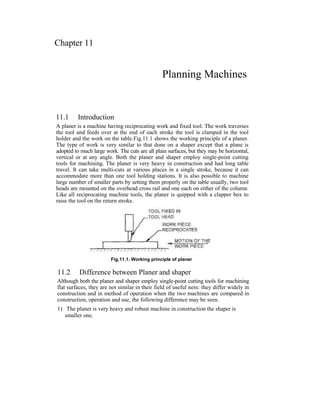
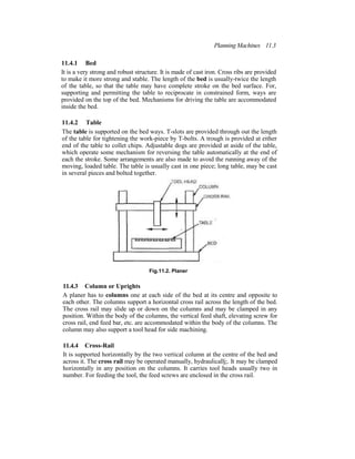
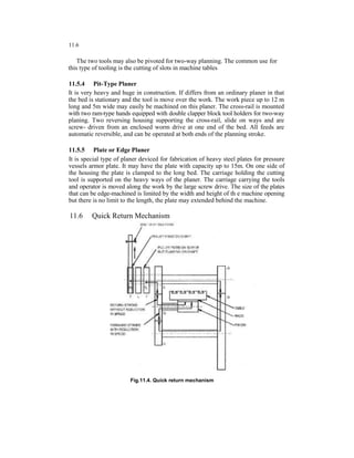
SlideShare a Scribd company logo
Chapter 11
Planning Machines
11.1 Introduction
A planer is a machine having reciprocating work and fixed tool. The work traverses
the tool and feeds over at the end of each stroke the tool is clamped in the tool
holder and the work on the table.Fig.11.1 shows the working principle of a planer.
The type of work is very similar to that done on a shaper except that a plane is
adopted to much large work. The cuts are all plain surfaces, but they may be horizontal,
vertical or at any angle. Both the planer and shaper employ single-point cutting
tools for machining. The planer is very heavy in construction and had long table
travel. It can take multi-cuts at various places in a single stroke, because it can
accommodate more than one tool holding stations. It is also possible to machine
large number of smaller parts by setting them properly on the table usually, two tool
heads are mounted on the overhead cross rail and one each on either of the column.
Like all reciprocating machine tools, the planer is quipped with a clapper box to
raise the tool on the return stroke.
Fig.11.1. Working principle of planer
11.2 Difference between Planer and shaper
Although both the planer and shaper employ single-point cutting tools for machining
flat surfaces, they are not similar in their field of useful ness: they differ widely in
construction and in method of operation when the two machines are compared in
construction, operation and use, the following difference may be seen.
1) The planer is very heavy and robust machine in construction the shaper is
smaller one.
11.2
2) On planer the work is moved against the stationary tool, on shaper the tool is moved
against the stationary work.
3) On planner the feed is given to the tool, on shaper the feed is given to the work.
4) In planer the work table is drive either by gears or by hydraulic means. The shaper ram
can also be driven in this manner, but in most cases the quick return mechanism is
used.
5) Most planers differ from shapers in that they approach constant velocity cuts.
6) The planer is specially adopted to large work; the shaper can do only small work.
7) In a planer the tool is rigidly supported when the work moves on precision ways and
maximum accuracy on the machined surface is assured. In a shaper, due to
overhanging of the ram during the cutting stroke, and the machine being not very
robust the accuracy cannot be expected up to the mark.
8) High rate of power consumption and overall rigidity in a planer enables it to take deep
cuts and apply heavy feeds to rough finish a job quickly. A planer can consume up to
150 h.p. Whereas a shaper can consume 15 to 20 h.p.
9) A planer is not suitable for machining relatively small, and medium size work or few at
a time that a shaper can do, but a planer is more economical and faster when large
quantities are machined. A large number of jobs of identical shapers can be machined
in one setting on a planer table.
10) Multiple tooling with double or four tool heads in a planer makes it possible to
machine more than one surface together, thus reducing cutting time.
11) In a planning machine, work setting requires much of skill and takes along time,
whereas in a shaper the work may be clamped easily and quickly.
12) Tools used in a planer are much more robust than that used in a shaper.
13) In modern planes wide range of cutting and return speeds are available and they may
be changed independently.
14) Planers are larger and costlier machines compared to shapers.
11.3 Planer Size
The size of a planer is determined by the maximum length of material the tool can machine
in one stroke. It includes the table size, (length and width) and its distance from the rail.
Other details are also mentioned to complete the specifications like type of drive, type of
speed reduction, power input, cutting to return stroke ratio etc.
11.4 Principle Parts of a Planer
The principle parts of a planer are as follows:
Planning Machines 11.3
11.4.1 Bed
It is a very strong and robust structure. It is made of cast iron. Cross ribs are provided
to make it more strong and stable. The length of the bed is usually-twice the length
of the table, so that the table may have complete stroke on the bed surface. For,
supporting and permitting the table to reciprocate in constrained form, ways are
provided on the top of the bed. Mechanisms for driving the table are accommodated
inside the bed.
11.4.2 Table
The table is supported on the bed ways. T-slots are provided through out the length
of the table for tightening the work-piece by T-bolts. A trough is provided at either
end of the table to collet chips. Adjustable dogs are provided at aside of the table,
which operate some mechanism for reversing the table automatically at the end of
each the stroke. Some arrangements are also made to avoid the running away of the
moving, loaded table. The table is usually cast in one piece; long table, may be cast
in several pieces and bolted together.
Fig.11.2. Planer
11.4.3 Column or Uprights
A planer has to columns one at each side of the bed at its centre and opposite to
each other. The columns support a horizontal cross rail across the length of the bed.
The cross rail may slide up or down on the columns and may be clamped in any
position. Within the body of the columns, the vertical feed shaft, elevating screw for
cross rail, end feed bar, etc. are accommodated within the body of the columns. The
column may also support a tool head for side machining.
11.4.4 Cross-Rail
It is supported horizontally by the two vertical column at the centre of the bed and
across it. The cross rail may be operated manually, hydraulicallj;. It may be clamped
horizontally in any position on the columns. It carries tool heads usually two in
number. For feeding the tool, the feed screws are enclosed in the cross rail.
11.4
11.4.5 Tool Head
Usually two tool heads are mounted on the horizontal cross rail and one on each
column. The tool head carries a tool post to hold the cutting tool. The tool post is
hinged on the tool head for lifting the tool in the return stroke. The tool may be
adjusted at an angle also, if desired.
Fig.11.3. Hydraulic open-planer
11.4.6 Control
The controls for governing the various actions of different parts of a planer are
provided in a centralised panel. From this central location the operator is able to
obtain very close control of all cutting tools. These controls are start, stop, automatic
cut, automatic return, speed reduce, etc.
11.5 Classification of Planer
According to the general construction the planers are of five types:
1) Double housing planer
2) Open-side planer
3) Universal planer
4) Pit type planer
5) Edge or plate planer.
Each of the above types may very according to the method of drive as follows:
1) Gear drive
2) Hydraulic drive
3) Screw drive
4) Belt drive
5) Variable-speed motor drive
6) Crank drive.
Planning Machines 11.5
Gear driven planers are generally used in the workshops. They have several times
more inertia force to over come than the hydraulic drive planers. Overcoming inertia
consumes energy and with rapid short strokes, the difference is power consumption
in noticeable hydraulic drives are highly satisfactory for planers. Advantages of
hydraulic drives are uniform cutting pressure, quick table reversal, rapid means of
varying the stroke and less noise in operation. Screw drive is employed principally
on plate planers. Belt drive is the oldest system in which the power is taken from an
overhead line shaft. Crank drive is found only on some small planers.
11.5.1 Double Housing Planer
It consists of a long heavy base on which the table or platen is reciprocated. The
upright housing is located at the side of the base near the centre to support the cross
rail. The cross rail supports the tool heads. The tool maybe feed manually or by
power in either a vertical or a crosswise direction. The motor drive usually at one
side of the planer near the centre, and the drive mechanism is located under the
table. The controls for operation are all at the upright housing The stroke length of
the table is controlled by the adjustable dogs at the side of the bed. The accuracy of
the planer depends upon the rigidity and the manner in which the bed ways are
machined.
Specifications (Fig.)
Planning width 1G00min
Length 4000-1200mm
Height 1600mm
Clamping surface of table 1400 x 4000 - 1200 mm
Vertical movement of the nead Slide 350 mm
Speeds (working) 4-18-28 m/min
Main drive motor 22 kw.
11.5.2 Open-Side Planer
The open side planer has housing on one side only. It is hydraulically driven and
used to handle wide work. It can be equipped with duplicating attachments for
machining irregular surfaces. On one side of the table, a master form is mounted so
that as the tracer moves over the surface, the cutting tool is moved accordingly.
Such device are usually hydraulically operated and are similar in operation to du-
plicating units used on other machine tools.
11.5.3 Universal Planer
The universal planer has two-edged tool pivoted in the fixed holder, which cuts on
both forward and reverse strokes. As the total engages the work, it pivots slightly
and is held against the block during the cut. At the end of the stroke the other
cutting edge is brought into position in the same way, which is somewhat longer
than the first, so that it will yield the proper depth cut on the return stroke.
11.6
The two tools may also be pivoted for two-way planning. The common use for
this type of tooling is the cutting of slots in machine tables
11.5.4 Pit-Type Planer
It is very heavy and huge in construction. If differs from an ordinary planer in that
the bed is stationary and the tool is move over the work. The work piece up to 12 m
long and 5m wide may easily be machined on this planer. The cross-rail is mounted
with two ram-type hands equipped with double clapper block tool holders for two-way
planing. Two reversing housing supporting the cross-rail, slide on ways and are
screw- driven from an enclosed worm drive at one end of the bed. All feeds are
automatic reversible, and can be operated at both ends of the planning stroke.
11.5.5 Plate or Edge Planer
It is special type of planer deviced for fabrication of heavy steel plates for pressure
vessels armor plate. It may have the plate with capacity up to 15m. On one side of
the housing the plate is clamped to the long bed. The carriage holding the cutting
tool is supported on the heavy ways of the planer. The carriage carrying the tools
and operator is moved along the work by the large screw drive. The size of the plates
that can be edge-machined is limited by the width and height of th e machine opening
but there is no limit to the length, the plate may extended behind the machine.
11.6 Quick Return Mechanism
Fig.11.4. Quick return mechanism
Planning Machines 11.7
Like shaper, a planer is also provided with quick return mechanism Fig.11.4 shows fast
and loose pulleys type quick return mechanism for a planer. In this mechanism, the belt-
shifting fork is connected to the dogs fitted at end of the stroke in the planer bed. These
automatically shift the belt from pulley P to P2 at the end of every stroke.
When the belt is on pulley Plf the motion is transmitted to the rack through gears A, B, C
and D, and is thus the speed is very much reduced. Thus it constitutes cutting stroke.
When the belt is on pulley P1( the motion is transmitted to rack through gears E and D. in
this case the motion is transmitted without any reduction, therefore it constitutes stroke.
Note that the pulley P: is fixed on the shaft. Pulley P2 is fixed on the sleeve but floating
on the shaft. The pulley between Pa and P2 is free on the shaft.
The quick return motion also obtained by D.C. reversible motor or by hydraulic
system.
The speed of the D.C reversible motor can be changed very quickly from full forward to
full backward. The reversal is instantaneous. At the end of the stroke, the trip dogs change
over the supply to the motor and it moves accordingly. This method is most commonly used
on modern because it gives a wide range of table speed and a more responsible control.
The hydraulic drive for planer is exactly similar to that of shaper. Most of the modern,
planers used hydraulic drive.
11.7 Feed Mechanism
In a planer the feed is provided intermittently and at the end of the return stroke similar to a
shaping machine. The feed of a planer, both downfeed and cross feed, is given by the tool.
The cross feed is given while machining horizontal surface on a work mounted on the table.
The tool which is clamped on the tool head slides on the cross rail by a predetermined
amount at the end of each return stroke of the table to give the necessary cross feed. The
downfeed is applied while machining a vertical or angular surface by rotating the downfeed
screw of the tool head. The power feed may be applied by the following methods.
1) By frication disc.
2) By electrical drive.
11.7.1 Feed Mechanism by Friction Disc
But in a planer as the length of the stroke of the table is quite long, the bull gear will make a
large number of revolutions in the forward cutting stroke and the same number of
revolutions in the return stroke. By friction feed disc, only part of the revolution of the bull
gear is used to operate the feed gearing at the end of the return stroke, and during the rest of
the period, the feed mechanism remains inoperative.
11.8
The sectional view of the feed disc is
shown in Fig.11.5. The feed disc
consists of two parts having a cylin-
drical opening, which encloses the
flange connected to the shaft. Leather
washers are placed between the flange
and the disc openings and the blots are
then frightened. A flexible connection is
now made between the shaft and the
feed disc through leather washers.
Fig.11.5 shows the end view of the
feed disc showing the driving mecha-
nism of the feed screws. A t-slot is cut radially on the face of the feed disc within
which a black is fitted. B rotating the
knurled knob the position of the block
with respect to the centre may be
changed. A pin connected to the
driving disc projects beyond the disc
body. When the cross feed shaft starts
rotating during forward cutting stroke
the motion is transmitted to the discs
by the flange shown in Fig.11.6 and
the disc starts rotating. The motion of
the disc is limited by the projecting pin
hitting against a fixed pin fitted upon
the machine frame. Thus when the disc
rotates through a part of the revolution,
the flange connected to the shaft
continues to rotate within the disc
slipping over the leather washers
throughout the cutting stroke. When
the table is reversed and the shaft starts
rotating in the opposite direction on the
disc rotates through the same part of
the revolution in the opposite direction
due to the pin hitting against a second
fixed pin mounted upon the machine
frame. Thus when the planer table
reciprocates, the disc rotates through a
part of the revolution in one direction at the
beginning of cutting stroke and again it
rotates through the same part of the revolution in the opposite direction at the
beginning of return stroke.
This rotary movement of the disc is transmitted to the rack through the connecting rod
and a pinion mounted upon the shaft, which meshes with the rack, receives
Fig.11.5. Selection view of a feed disc
Fig.11.6. Feed disc and automatic
feed mechanism
Planning Machines 11.9
rotary movement. Big gear is free on the shaft. A double pawl is pinned on the face
of the gear and any one end of the pawl may be pushed into the tooth space of the
gear. When the left hand end of the pawl is pushed within the gear, the upward
movement of the rack will cause the pinion to rotate in the clockwise direction and
the motion is communicated to the gear through the pawl and gear will rotate in the
clockwise direction. When the rack will be moving downward, the pinion will rotate
in the anti-clock wise direction and no motion will be transmitted to the gear, as the
bevel edge of the pawl will slip over the teeth of pinion. Thus the gear will rotate
through a part of the revolution in one direction only during a complete double
stroke of the table and it may be so arranged that the gear will operate during the
beginning of cutting stroke only. Gear may be made to mesh with two sliding gears
and mounted upon the downfeed shaft and crossfeed shaft contained within the
cross rail. Feed shafts separately or together. The direction of feed movement may
be reversed by changing the position of double pawl.
Amount of fed movement may be varied by shitting the position of block with
respect to the centre. Feed is incresed when the block is shifted away from the centre.
The stroke length of the rack is increased due to the greatere throw of eccentricity of
the block and the two gears and ultimately rotate through a greater amount.
11.7.2 Electrical Feed Movement
Modern planers, which are equipped with electrical, drive used a separate motor to
operate the feed mechanism. The motor is energised simultaneously with the table
reversing mechanism and rotates through a definite part of revolution. The revolution
of the motor may be half or one revolution only. At the appropriate time, the electrical
control trips off the supply of electrical current and the motor is stopped by dynamic
braking.
11.8 Planer Operations
The common operations performed in planer are:
1) Planing flat horizontal surfaces.
2) Planing vertical surfaces.
3) Planing at an angle and machining dovetails.
4) Planing curved surfaces.
5) Planing slots and grooves.
11.8.1 Planing Horizontal Surface
While machining horizontal surface, the work is given a reciprocating movement
along with the table and the tool is feed cross wise to complete the cut. Both the
railheads may be used for simultaneous removal of the metal from two cutting edges.
The work is supported properly on the table. Proper planing tool is selected the
depth of cut speed and feed are adjusted and the work is finished to the required
dimension by taking roughing and finishing cuts.
11.10
11.8.2 Planing Vertical Surface
The vertical surface of the work is planed by adjusting the saddle horizontal along
the cross rail until the tool is in a position to give the required depth of cut. The
vertical slide is adjusted perpendicular to the planer table and the apron is swivelled
in a direction so that the tool will swing clear out of the machined surface during the
return stroke. The downfeed is given by rotating the down feed screw.
11.8.3 Planing Angular Surface
The tool head is swivelled to the required angle and the apron is then further swivelled
away from the work to give relief to the tool cutting edge during the return stroke.
By rotating the downfeed screw the tool is fed at an angle to the planer table.
11.8.4 Planing Formed Surface
Fig.11.7 shows a simple method of planing a concave surface with the aid of a
special fixture consisting of a radius arm and a bracket. The bracket is connected to
the cross number attached to the two housings. One end of the radius arm is pivoted
on the bracket and the other end to the vertical slide of the tool head. The down feed
screw of the tool head is removed while planing the cross feed is engaged which
causes the saddle to traverse the cross rail and the tool which is guided by the radius
arm planes a concave surface. The radius of concave surface is dependent upon the
length of the radius arm.
Fig.11.7. Planing concave surface
11.8.5 Planing Slots or Grooves
Slots or grooves are cut by using slotting tools. The operation is similar to that of a
shaper.
Planning Machines
11.11
11.9 Cutting Speed, Feed and Depth of cut
11.9.1 Cutting Speed
As in shaper the cutting speed of a planer is the rate at which the metal is removed
during forward cutting stroke. This is expressed in m/min.
11.9.2 Feed
The feed in a planing machine is the distance the tool head travels at the begining of
each cutting stroke expressed in mm per double stroke.
11.9.3 Depth of cut
It is the thickness of metal removed in one cut and is measured by the perpendicular
distance between the machined and non-machined surface expressed in mm.
11.10 Machining Time
If the cutting speed, feed , length of cutting stroke, breadth of the job and number of
the double strokes per minute for a planer operation are known, the machining time
required for one complete cut may be calculated by using the formula.
The ratio of cutting time to return time usually varies from 2:1 to 4:1.
11.11 Planer Tools
The tools used in planer and shaper work are of
the same general type as those used on a lathe
but are heavier in construction.
Forged tools maybe used, but the tool
holders with removable bits are generally
used for heavy work on large machines.
Fig.11.9 shows some of the cutting tool shapers
for planer operations. They are usually tipped Fig.11.8. Left hand dovetail end
with high-speed steel, cast alloy or carbide cutting roughing tool
inserts. High-speed steel or cast alloy are
commonly used in heavy roughing cuts and carbides for secondary roughing and
finishing. Cutting angles for tools depend on the type of tool used and the material
being cut. They are similar to angles used on other single point tools, but the end
clearance need not exceed 4 degrees.
Fig.11.9. Cutting tool shapers for planer operations

More Related Content

What's hot

Shaper machine
Shaper   machineShaper   machine
Shaper machine
rajetyadav
 

What's hot (20)

Milling machine
Milling machineMilling machine
Milling machine
 
Lathe
LatheLathe
Lathe
 
Unit 1 Metal Cutting
Unit 1 Metal CuttingUnit 1 Metal Cutting
Unit 1 Metal Cutting
 
Single point cutting tool
Single point cutting toolSingle point cutting tool
Single point cutting tool
 
Classification and Types of Press
Classification and Types of PressClassification and Types of Press
Classification and Types of Press
 
Capston and turrent lathe
Capston and turrent latheCapston and turrent lathe
Capston and turrent lathe
 
3.cutting tools nomenclature
3.cutting tools nomenclature3.cutting tools nomenclature
3.cutting tools nomenclature
 
Milling & Gear Cutting
Milling & Gear CuttingMilling & Gear Cutting
Milling & Gear Cutting
 
Milling machine
Milling machineMilling machine
Milling machine
 
Automatic machines
Automatic machinesAutomatic machines
Automatic machines
 
Slotter machine
Slotter machineSlotter machine
Slotter machine
 
CNC introduction and advantages and disadvantages
CNC introduction and advantages and disadvantages CNC introduction and advantages and disadvantages
CNC introduction and advantages and disadvantages
 
Lathe machine
Lathe machineLathe machine
Lathe machine
 
Boring machine
Boring machineBoring machine
Boring machine
 
Punching and Blanking Process (Sheet Metal Forming)
Punching and Blanking Process (Sheet Metal Forming)Punching and Blanking Process (Sheet Metal Forming)
Punching and Blanking Process (Sheet Metal Forming)
 
cutting tool materials
cutting tool materialscutting tool materials
cutting tool materials
 
PRINCIPLE OF LATHE MACHINE
PRINCIPLE OF LATHE MACHINEPRINCIPLE OF LATHE MACHINE
PRINCIPLE OF LATHE MACHINE
 
Super finishing Processes
Super finishing ProcessesSuper finishing Processes
Super finishing Processes
 
Shaper machine
Shaper   machineShaper   machine
Shaper machine
 
Capstan, Turret & Automatic lathe
Capstan, Turret & Automatic latheCapstan, Turret & Automatic lathe
Capstan, Turret & Automatic lathe
 

Similar to Planning machine

shaper machine
shaper machineshaper machine
shaper machine
seu
 

Similar to Planning machine (20)

Planer
PlanerPlaner
Planer
 
Planner machineppt by polayya
Planner machineppt by polayyaPlanner machineppt by polayya
Planner machineppt by polayya
 
Project documents on weight optimization of lathe bed
Project documents on weight optimization of lathe bedProject documents on weight optimization of lathe bed
Project documents on weight optimization of lathe bed
 
Shaping machine
Shaping machineShaping machine
Shaping machine
 
Planer
PlanerPlaner
Planer
 
Drilling machine
Drilling machineDrilling machine
Drilling machine
 
Manufacturing Processes
Manufacturing ProcessesManufacturing Processes
Manufacturing Processes
 
Mp1 presentation
Mp1 presentationMp1 presentation
Mp1 presentation
 
Manufacturing process ii
Manufacturing process iiManufacturing process ii
Manufacturing process ii
 
Shaper, Planer and Slotter
Shaper, Planer and SlotterShaper, Planer and Slotter
Shaper, Planer and Slotter
 
mt lab-1 updated (1).pdf
mt lab-1 updated (1).pdfmt lab-1 updated (1).pdf
mt lab-1 updated (1).pdf
 
mt lab-1 updated.docx
mt lab-1 updated.docxmt lab-1 updated.docx
mt lab-1 updated.docx
 
Slotter and plannar machine tools
Slotter and plannar machine toolsSlotter and plannar machine tools
Slotter and plannar machine tools
 
Planer
PlanerPlaner
Planer
 
Milling machine
Milling machineMilling machine
Milling machine
 
Machine tool section a
Machine tool  section aMachine tool  section a
Machine tool section a
 
planer-machine by sherwin opeda
 planer-machine by sherwin opeda planer-machine by sherwin opeda
planer-machine by sherwin opeda
 
shaper machine
shaper machineshaper machine
shaper machine
 
lathe machine
lathe machinelathe machine
lathe machine
 
Slotting machine
Slotting machineSlotting machine
Slotting machine
 

More from nmahi96

Personal Survival and Social Responsibilities(PSSR)
Personal Survival and Social Responsibilities(PSSR)Personal Survival and Social Responsibilities(PSSR)
Personal Survival and Social Responsibilities(PSSR)
nmahi96
 

More from nmahi96 (20)

Matlab lab manual
Matlab lab manualMatlab lab manual
Matlab lab manual
 
Heat transfer(HT) lab manual
Heat transfer(HT) lab manualHeat transfer(HT) lab manual
Heat transfer(HT) lab manual
 
STSDSD
STSDSDSTSDSD
STSDSD
 
Personal Survival Techniques(PST)
Personal Survival Techniques(PST)Personal Survival Techniques(PST)
Personal Survival Techniques(PST)
 
Personal Survival and Social Responsibilities(PSSR)
Personal Survival and Social Responsibilities(PSSR)Personal Survival and Social Responsibilities(PSSR)
Personal Survival and Social Responsibilities(PSSR)
 
Fire prevention and Fire Fighting(FPFF)
Fire prevention and Fire Fighting(FPFF)Fire prevention and Fire Fighting(FPFF)
Fire prevention and Fire Fighting(FPFF)
 
Elementary First Aid(EFA)
Elementary First Aid(EFA)Elementary First Aid(EFA)
Elementary First Aid(EFA)
 
INERT GAS SYSTEM(IG)
INERT GAS SYSTEM(IG)INERT GAS SYSTEM(IG)
INERT GAS SYSTEM(IG)
 
Practical Marine Electrical Knowledge 2ed 1999
Practical Marine Electrical Knowledge 2ed 1999Practical Marine Electrical Knowledge 2ed 1999
Practical Marine Electrical Knowledge 2ed 1999
 
Sensors
SensorsSensors
Sensors
 
Graduate marine engineering(GME)important questions
Graduate marine engineering(GME)important questionsGraduate marine engineering(GME)important questions
Graduate marine engineering(GME)important questions
 
FEA intro patran_nastran
FEA intro patran_nastranFEA intro patran_nastran
FEA intro patran_nastran
 
Ansys beam problem
Ansys beam problemAnsys beam problem
Ansys beam problem
 
Ansys
Ansys Ansys
Ansys
 
Screw thread measurement
Screw thread measurementScrew thread measurement
Screw thread measurement
 
Optical measuring instruments
Optical measuring instrumentsOptical measuring instruments
Optical measuring instruments
 
Tolerance and Fits
Tolerance and FitsTolerance and Fits
Tolerance and Fits
 
Ignition system
Ignition systemIgnition system
Ignition system
 
Clutch system
Clutch systemClutch system
Clutch system
 
Braking system
Braking systemBraking system
Braking system
 

Recently uploaded

Fruit shop management system project report.pdf
Fruit shop management system project report.pdfFruit shop management system project report.pdf
Fruit shop management system project report.pdf
Kamal Acharya
 
power quality voltage fluctuation UNIT - I.pptx
power quality voltage fluctuation UNIT - I.pptxpower quality voltage fluctuation UNIT - I.pptx
power quality voltage fluctuation UNIT - I.pptx
ViniHema
 
Digital Signal Processing Lecture notes n.pdf
Digital Signal Processing Lecture notes n.pdfDigital Signal Processing Lecture notes n.pdf
Digital Signal Processing Lecture notes n.pdf
AbrahamGadissa
 
RS Khurmi Machine Design Clutch and Brake Exercise Numerical Solutions
RS Khurmi Machine Design Clutch and Brake Exercise Numerical SolutionsRS Khurmi Machine Design Clutch and Brake Exercise Numerical Solutions
RS Khurmi Machine Design Clutch and Brake Exercise Numerical Solutions
Atif Razi
 
Hall booking system project report .pdf
Hall booking system project report  .pdfHall booking system project report  .pdf
Hall booking system project report .pdf
Kamal Acharya
 
CFD Simulation of By-pass Flow in a HRSG module by R&R Consult.pptx
CFD Simulation of By-pass Flow in a HRSG module by R&R Consult.pptxCFD Simulation of By-pass Flow in a HRSG module by R&R Consult.pptx
CFD Simulation of By-pass Flow in a HRSG module by R&R Consult.pptx
R&R Consult
 
LIGA(E)11111111111111111111111111111111111111111.ppt
LIGA(E)11111111111111111111111111111111111111111.pptLIGA(E)11111111111111111111111111111111111111111.ppt
LIGA(E)11111111111111111111111111111111111111111.ppt
ssuser9bd3ba
 

Recently uploaded (20)

Danfoss NeoCharge Technology -A Revolution in 2024.pdf
Danfoss NeoCharge Technology -A Revolution in 2024.pdfDanfoss NeoCharge Technology -A Revolution in 2024.pdf
Danfoss NeoCharge Technology -A Revolution in 2024.pdf
 
Fruit shop management system project report.pdf
Fruit shop management system project report.pdfFruit shop management system project report.pdf
Fruit shop management system project report.pdf
 
power quality voltage fluctuation UNIT - I.pptx
power quality voltage fluctuation UNIT - I.pptxpower quality voltage fluctuation UNIT - I.pptx
power quality voltage fluctuation UNIT - I.pptx
 
Digital Signal Processing Lecture notes n.pdf
Digital Signal Processing Lecture notes n.pdfDigital Signal Processing Lecture notes n.pdf
Digital Signal Processing Lecture notes n.pdf
 
NO1 Pandit Amil Baba In Bahawalpur, Sargodha, Sialkot, Sheikhupura, Rahim Yar...
NO1 Pandit Amil Baba In Bahawalpur, Sargodha, Sialkot, Sheikhupura, Rahim Yar...NO1 Pandit Amil Baba In Bahawalpur, Sargodha, Sialkot, Sheikhupura, Rahim Yar...
NO1 Pandit Amil Baba In Bahawalpur, Sargodha, Sialkot, Sheikhupura, Rahim Yar...
 
The Ultimate Guide to External Floating Roofs for Oil Storage Tanks.docx
The Ultimate Guide to External Floating Roofs for Oil Storage Tanks.docxThe Ultimate Guide to External Floating Roofs for Oil Storage Tanks.docx
The Ultimate Guide to External Floating Roofs for Oil Storage Tanks.docx
 
Top 13 Famous Civil Engineering Scientist
Top 13 Famous Civil Engineering ScientistTop 13 Famous Civil Engineering Scientist
Top 13 Famous Civil Engineering Scientist
 
Democratizing Fuzzing at Scale by Abhishek Arya
Democratizing Fuzzing at Scale by Abhishek AryaDemocratizing Fuzzing at Scale by Abhishek Arya
Democratizing Fuzzing at Scale by Abhishek Arya
 
WATER CRISIS and its solutions-pptx 1234
WATER CRISIS and its solutions-pptx 1234WATER CRISIS and its solutions-pptx 1234
WATER CRISIS and its solutions-pptx 1234
 
RS Khurmi Machine Design Clutch and Brake Exercise Numerical Solutions
RS Khurmi Machine Design Clutch and Brake Exercise Numerical SolutionsRS Khurmi Machine Design Clutch and Brake Exercise Numerical Solutions
RS Khurmi Machine Design Clutch and Brake Exercise Numerical Solutions
 
ENERGY STORAGE DEVICES INTRODUCTION UNIT-I
ENERGY STORAGE DEVICES  INTRODUCTION UNIT-IENERGY STORAGE DEVICES  INTRODUCTION UNIT-I
ENERGY STORAGE DEVICES INTRODUCTION UNIT-I
 
Explosives Industry manufacturing process.pdf
Explosives Industry manufacturing process.pdfExplosives Industry manufacturing process.pdf
Explosives Industry manufacturing process.pdf
 
Hall booking system project report .pdf
Hall booking system project report  .pdfHall booking system project report  .pdf
Hall booking system project report .pdf
 
CFD Simulation of By-pass Flow in a HRSG module by R&R Consult.pptx
CFD Simulation of By-pass Flow in a HRSG module by R&R Consult.pptxCFD Simulation of By-pass Flow in a HRSG module by R&R Consult.pptx
CFD Simulation of By-pass Flow in a HRSG module by R&R Consult.pptx
 
Cloud-Computing_CSE311_Computer-Networking CSE GUB BD - Shahidul.pptx
Cloud-Computing_CSE311_Computer-Networking CSE GUB BD - Shahidul.pptxCloud-Computing_CSE311_Computer-Networking CSE GUB BD - Shahidul.pptx
Cloud-Computing_CSE311_Computer-Networking CSE GUB BD - Shahidul.pptx
 
Toll tax management system project report..pdf
Toll tax management system project report..pdfToll tax management system project report..pdf
Toll tax management system project report..pdf
 
LIGA(E)11111111111111111111111111111111111111111.ppt
LIGA(E)11111111111111111111111111111111111111111.pptLIGA(E)11111111111111111111111111111111111111111.ppt
LIGA(E)11111111111111111111111111111111111111111.ppt
 
fundamentals of drawing and isometric and orthographic projection
fundamentals of drawing and isometric and orthographic projectionfundamentals of drawing and isometric and orthographic projection
fundamentals of drawing and isometric and orthographic projection
 
A CASE STUDY ON ONLINE TICKET BOOKING SYSTEM PROJECT.pdf
A CASE STUDY ON ONLINE TICKET BOOKING SYSTEM PROJECT.pdfA CASE STUDY ON ONLINE TICKET BOOKING SYSTEM PROJECT.pdf
A CASE STUDY ON ONLINE TICKET BOOKING SYSTEM PROJECT.pdf
 
Arduino based vehicle speed tracker project
Arduino based vehicle speed tracker projectArduino based vehicle speed tracker project
Arduino based vehicle speed tracker project
 

Planning machine

  • 1. Chapter 11 Planning Machines 11.1 Introduction A planer is a machine having reciprocating work and fixed tool. The work traverses the tool and feeds over at the end of each stroke the tool is clamped in the tool holder and the work on the table.Fig.11.1 shows the working principle of a planer. The type of work is very similar to that done on a shaper except that a plane is adopted to much large work. The cuts are all plain surfaces, but they may be horizontal, vertical or at any angle. Both the planer and shaper employ single-point cutting tools for machining. The planer is very heavy in construction and had long table travel. It can take multi-cuts at various places in a single stroke, because it can accommodate more than one tool holding stations. It is also possible to machine large number of smaller parts by setting them properly on the table usually, two tool heads are mounted on the overhead cross rail and one each on either of the column. Like all reciprocating machine tools, the planer is quipped with a clapper box to raise the tool on the return stroke. Fig.11.1. Working principle of planer 11.2 Difference between Planer and shaper Although both the planer and shaper employ single-point cutting tools for machining flat surfaces, they are not similar in their field of useful ness: they differ widely in construction and in method of operation when the two machines are compared in construction, operation and use, the following difference may be seen. 1) The planer is very heavy and robust machine in construction the shaper is smaller one.
  • 2. 11.2 2) On planer the work is moved against the stationary tool, on shaper the tool is moved against the stationary work. 3) On planner the feed is given to the tool, on shaper the feed is given to the work. 4) In planer the work table is drive either by gears or by hydraulic means. The shaper ram can also be driven in this manner, but in most cases the quick return mechanism is used. 5) Most planers differ from shapers in that they approach constant velocity cuts. 6) The planer is specially adopted to large work; the shaper can do only small work. 7) In a planer the tool is rigidly supported when the work moves on precision ways and maximum accuracy on the machined surface is assured. In a shaper, due to overhanging of the ram during the cutting stroke, and the machine being not very robust the accuracy cannot be expected up to the mark. 8) High rate of power consumption and overall rigidity in a planer enables it to take deep cuts and apply heavy feeds to rough finish a job quickly. A planer can consume up to 150 h.p. Whereas a shaper can consume 15 to 20 h.p. 9) A planer is not suitable for machining relatively small, and medium size work or few at a time that a shaper can do, but a planer is more economical and faster when large quantities are machined. A large number of jobs of identical shapers can be machined in one setting on a planer table. 10) Multiple tooling with double or four tool heads in a planer makes it possible to machine more than one surface together, thus reducing cutting time. 11) In a planning machine, work setting requires much of skill and takes along time, whereas in a shaper the work may be clamped easily and quickly. 12) Tools used in a planer are much more robust than that used in a shaper. 13) In modern planes wide range of cutting and return speeds are available and they may be changed independently. 14) Planers are larger and costlier machines compared to shapers. 11.3 Planer Size The size of a planer is determined by the maximum length of material the tool can machine in one stroke. It includes the table size, (length and width) and its distance from the rail. Other details are also mentioned to complete the specifications like type of drive, type of speed reduction, power input, cutting to return stroke ratio etc. 11.4 Principle Parts of a Planer The principle parts of a planer are as follows:
  • 3. Planning Machines 11.3 11.4.1 Bed It is a very strong and robust structure. It is made of cast iron. Cross ribs are provided to make it more strong and stable. The length of the bed is usually-twice the length of the table, so that the table may have complete stroke on the bed surface. For, supporting and permitting the table to reciprocate in constrained form, ways are provided on the top of the bed. Mechanisms for driving the table are accommodated inside the bed. 11.4.2 Table The table is supported on the bed ways. T-slots are provided through out the length of the table for tightening the work-piece by T-bolts. A trough is provided at either end of the table to collet chips. Adjustable dogs are provided at aside of the table, which operate some mechanism for reversing the table automatically at the end of each the stroke. Some arrangements are also made to avoid the running away of the moving, loaded table. The table is usually cast in one piece; long table, may be cast in several pieces and bolted together. Fig.11.2. Planer 11.4.3 Column or Uprights A planer has to columns one at each side of the bed at its centre and opposite to each other. The columns support a horizontal cross rail across the length of the bed. The cross rail may slide up or down on the columns and may be clamped in any position. Within the body of the columns, the vertical feed shaft, elevating screw for cross rail, end feed bar, etc. are accommodated within the body of the columns. The column may also support a tool head for side machining. 11.4.4 Cross-Rail It is supported horizontally by the two vertical column at the centre of the bed and across it. The cross rail may be operated manually, hydraulicallj;. It may be clamped horizontally in any position on the columns. It carries tool heads usually two in number. For feeding the tool, the feed screws are enclosed in the cross rail.
  • 4. 11.4 11.4.5 Tool Head Usually two tool heads are mounted on the horizontal cross rail and one on each column. The tool head carries a tool post to hold the cutting tool. The tool post is hinged on the tool head for lifting the tool in the return stroke. The tool may be adjusted at an angle also, if desired. Fig.11.3. Hydraulic open-planer 11.4.6 Control The controls for governing the various actions of different parts of a planer are provided in a centralised panel. From this central location the operator is able to obtain very close control of all cutting tools. These controls are start, stop, automatic cut, automatic return, speed reduce, etc. 11.5 Classification of Planer According to the general construction the planers are of five types: 1) Double housing planer 2) Open-side planer 3) Universal planer 4) Pit type planer 5) Edge or plate planer. Each of the above types may very according to the method of drive as follows: 1) Gear drive 2) Hydraulic drive 3) Screw drive 4) Belt drive 5) Variable-speed motor drive 6) Crank drive.
  • 5. Planning Machines 11.5 Gear driven planers are generally used in the workshops. They have several times more inertia force to over come than the hydraulic drive planers. Overcoming inertia consumes energy and with rapid short strokes, the difference is power consumption in noticeable hydraulic drives are highly satisfactory for planers. Advantages of hydraulic drives are uniform cutting pressure, quick table reversal, rapid means of varying the stroke and less noise in operation. Screw drive is employed principally on plate planers. Belt drive is the oldest system in which the power is taken from an overhead line shaft. Crank drive is found only on some small planers. 11.5.1 Double Housing Planer It consists of a long heavy base on which the table or platen is reciprocated. The upright housing is located at the side of the base near the centre to support the cross rail. The cross rail supports the tool heads. The tool maybe feed manually or by power in either a vertical or a crosswise direction. The motor drive usually at one side of the planer near the centre, and the drive mechanism is located under the table. The controls for operation are all at the upright housing The stroke length of the table is controlled by the adjustable dogs at the side of the bed. The accuracy of the planer depends upon the rigidity and the manner in which the bed ways are machined. Specifications (Fig.) Planning width 1G00min Length 4000-1200mm Height 1600mm Clamping surface of table 1400 x 4000 - 1200 mm Vertical movement of the nead Slide 350 mm Speeds (working) 4-18-28 m/min Main drive motor 22 kw. 11.5.2 Open-Side Planer The open side planer has housing on one side only. It is hydraulically driven and used to handle wide work. It can be equipped with duplicating attachments for machining irregular surfaces. On one side of the table, a master form is mounted so that as the tracer moves over the surface, the cutting tool is moved accordingly. Such device are usually hydraulically operated and are similar in operation to du- plicating units used on other machine tools. 11.5.3 Universal Planer The universal planer has two-edged tool pivoted in the fixed holder, which cuts on both forward and reverse strokes. As the total engages the work, it pivots slightly and is held against the block during the cut. At the end of the stroke the other cutting edge is brought into position in the same way, which is somewhat longer than the first, so that it will yield the proper depth cut on the return stroke.
  • 6. 11.6 The two tools may also be pivoted for two-way planning. The common use for this type of tooling is the cutting of slots in machine tables 11.5.4 Pit-Type Planer It is very heavy and huge in construction. If differs from an ordinary planer in that the bed is stationary and the tool is move over the work. The work piece up to 12 m long and 5m wide may easily be machined on this planer. The cross-rail is mounted with two ram-type hands equipped with double clapper block tool holders for two-way planing. Two reversing housing supporting the cross-rail, slide on ways and are screw- driven from an enclosed worm drive at one end of the bed. All feeds are automatic reversible, and can be operated at both ends of the planning stroke. 11.5.5 Plate or Edge Planer It is special type of planer deviced for fabrication of heavy steel plates for pressure vessels armor plate. It may have the plate with capacity up to 15m. On one side of the housing the plate is clamped to the long bed. The carriage holding the cutting tool is supported on the heavy ways of the planer. The carriage carrying the tools and operator is moved along the work by the large screw drive. The size of the plates that can be edge-machined is limited by the width and height of th e machine opening but there is no limit to the length, the plate may extended behind the machine. 11.6 Quick Return Mechanism Fig.11.4. Quick return mechanism
  • 7. Planning Machines 11.7 Like shaper, a planer is also provided with quick return mechanism Fig.11.4 shows fast and loose pulleys type quick return mechanism for a planer. In this mechanism, the belt- shifting fork is connected to the dogs fitted at end of the stroke in the planer bed. These automatically shift the belt from pulley P to P2 at the end of every stroke. When the belt is on pulley Plf the motion is transmitted to the rack through gears A, B, C and D, and is thus the speed is very much reduced. Thus it constitutes cutting stroke. When the belt is on pulley P1( the motion is transmitted to rack through gears E and D. in this case the motion is transmitted without any reduction, therefore it constitutes stroke. Note that the pulley P: is fixed on the shaft. Pulley P2 is fixed on the sleeve but floating on the shaft. The pulley between Pa and P2 is free on the shaft. The quick return motion also obtained by D.C. reversible motor or by hydraulic system. The speed of the D.C reversible motor can be changed very quickly from full forward to full backward. The reversal is instantaneous. At the end of the stroke, the trip dogs change over the supply to the motor and it moves accordingly. This method is most commonly used on modern because it gives a wide range of table speed and a more responsible control. The hydraulic drive for planer is exactly similar to that of shaper. Most of the modern, planers used hydraulic drive. 11.7 Feed Mechanism In a planer the feed is provided intermittently and at the end of the return stroke similar to a shaping machine. The feed of a planer, both downfeed and cross feed, is given by the tool. The cross feed is given while machining horizontal surface on a work mounted on the table. The tool which is clamped on the tool head slides on the cross rail by a predetermined amount at the end of each return stroke of the table to give the necessary cross feed. The downfeed is applied while machining a vertical or angular surface by rotating the downfeed screw of the tool head. The power feed may be applied by the following methods. 1) By frication disc. 2) By electrical drive. 11.7.1 Feed Mechanism by Friction Disc But in a planer as the length of the stroke of the table is quite long, the bull gear will make a large number of revolutions in the forward cutting stroke and the same number of revolutions in the return stroke. By friction feed disc, only part of the revolution of the bull gear is used to operate the feed gearing at the end of the return stroke, and during the rest of the period, the feed mechanism remains inoperative.
  • 8. 11.8 The sectional view of the feed disc is shown in Fig.11.5. The feed disc consists of two parts having a cylin- drical opening, which encloses the flange connected to the shaft. Leather washers are placed between the flange and the disc openings and the blots are then frightened. A flexible connection is now made between the shaft and the feed disc through leather washers. Fig.11.5 shows the end view of the feed disc showing the driving mecha- nism of the feed screws. A t-slot is cut radially on the face of the feed disc within which a black is fitted. B rotating the knurled knob the position of the block with respect to the centre may be changed. A pin connected to the driving disc projects beyond the disc body. When the cross feed shaft starts rotating during forward cutting stroke the motion is transmitted to the discs by the flange shown in Fig.11.6 and the disc starts rotating. The motion of the disc is limited by the projecting pin hitting against a fixed pin fitted upon the machine frame. Thus when the disc rotates through a part of the revolution, the flange connected to the shaft continues to rotate within the disc slipping over the leather washers throughout the cutting stroke. When the table is reversed and the shaft starts rotating in the opposite direction on the disc rotates through the same part of the revolution in the opposite direction due to the pin hitting against a second fixed pin mounted upon the machine frame. Thus when the planer table reciprocates, the disc rotates through a part of the revolution in one direction at the beginning of cutting stroke and again it rotates through the same part of the revolution in the opposite direction at the beginning of return stroke. This rotary movement of the disc is transmitted to the rack through the connecting rod and a pinion mounted upon the shaft, which meshes with the rack, receives Fig.11.5. Selection view of a feed disc Fig.11.6. Feed disc and automatic feed mechanism
  • 9. Planning Machines 11.9 rotary movement. Big gear is free on the shaft. A double pawl is pinned on the face of the gear and any one end of the pawl may be pushed into the tooth space of the gear. When the left hand end of the pawl is pushed within the gear, the upward movement of the rack will cause the pinion to rotate in the clockwise direction and the motion is communicated to the gear through the pawl and gear will rotate in the clockwise direction. When the rack will be moving downward, the pinion will rotate in the anti-clock wise direction and no motion will be transmitted to the gear, as the bevel edge of the pawl will slip over the teeth of pinion. Thus the gear will rotate through a part of the revolution in one direction only during a complete double stroke of the table and it may be so arranged that the gear will operate during the beginning of cutting stroke only. Gear may be made to mesh with two sliding gears and mounted upon the downfeed shaft and crossfeed shaft contained within the cross rail. Feed shafts separately or together. The direction of feed movement may be reversed by changing the position of double pawl. Amount of fed movement may be varied by shitting the position of block with respect to the centre. Feed is incresed when the block is shifted away from the centre. The stroke length of the rack is increased due to the greatere throw of eccentricity of the block and the two gears and ultimately rotate through a greater amount. 11.7.2 Electrical Feed Movement Modern planers, which are equipped with electrical, drive used a separate motor to operate the feed mechanism. The motor is energised simultaneously with the table reversing mechanism and rotates through a definite part of revolution. The revolution of the motor may be half or one revolution only. At the appropriate time, the electrical control trips off the supply of electrical current and the motor is stopped by dynamic braking. 11.8 Planer Operations The common operations performed in planer are: 1) Planing flat horizontal surfaces. 2) Planing vertical surfaces. 3) Planing at an angle and machining dovetails. 4) Planing curved surfaces. 5) Planing slots and grooves. 11.8.1 Planing Horizontal Surface While machining horizontal surface, the work is given a reciprocating movement along with the table and the tool is feed cross wise to complete the cut. Both the railheads may be used for simultaneous removal of the metal from two cutting edges. The work is supported properly on the table. Proper planing tool is selected the depth of cut speed and feed are adjusted and the work is finished to the required dimension by taking roughing and finishing cuts.
  • 10. 11.10 11.8.2 Planing Vertical Surface The vertical surface of the work is planed by adjusting the saddle horizontal along the cross rail until the tool is in a position to give the required depth of cut. The vertical slide is adjusted perpendicular to the planer table and the apron is swivelled in a direction so that the tool will swing clear out of the machined surface during the return stroke. The downfeed is given by rotating the down feed screw. 11.8.3 Planing Angular Surface The tool head is swivelled to the required angle and the apron is then further swivelled away from the work to give relief to the tool cutting edge during the return stroke. By rotating the downfeed screw the tool is fed at an angle to the planer table. 11.8.4 Planing Formed Surface Fig.11.7 shows a simple method of planing a concave surface with the aid of a special fixture consisting of a radius arm and a bracket. The bracket is connected to the cross number attached to the two housings. One end of the radius arm is pivoted on the bracket and the other end to the vertical slide of the tool head. The down feed screw of the tool head is removed while planing the cross feed is engaged which causes the saddle to traverse the cross rail and the tool which is guided by the radius arm planes a concave surface. The radius of concave surface is dependent upon the length of the radius arm. Fig.11.7. Planing concave surface 11.8.5 Planing Slots or Grooves Slots or grooves are cut by using slotting tools. The operation is similar to that of a shaper.
  • 11. Planning Machines 11.11 11.9 Cutting Speed, Feed and Depth of cut 11.9.1 Cutting Speed As in shaper the cutting speed of a planer is the rate at which the metal is removed during forward cutting stroke. This is expressed in m/min. 11.9.2 Feed The feed in a planing machine is the distance the tool head travels at the begining of each cutting stroke expressed in mm per double stroke. 11.9.3 Depth of cut It is the thickness of metal removed in one cut and is measured by the perpendicular distance between the machined and non-machined surface expressed in mm. 11.10 Machining Time If the cutting speed, feed , length of cutting stroke, breadth of the job and number of the double strokes per minute for a planer operation are known, the machining time required for one complete cut may be calculated by using the formula. The ratio of cutting time to return time usually varies from 2:1 to 4:1. 11.11 Planer Tools The tools used in planer and shaper work are of the same general type as those used on a lathe but are heavier in construction. Forged tools maybe used, but the tool holders with removable bits are generally used for heavy work on large machines. Fig.11.9 shows some of the cutting tool shapers for planer operations. They are usually tipped Fig.11.8. Left hand dovetail end with high-speed steel, cast alloy or carbide cutting roughing tool inserts. High-speed steel or cast alloy are commonly used in heavy roughing cuts and carbides for secondary roughing and finishing. Cutting angles for tools depend on the type of tool used and the material being cut. They are similar to angles used on other single point tools, but the end clearance need not exceed 4 degrees. Fig.11.9. Cutting tool shapers for planer operations