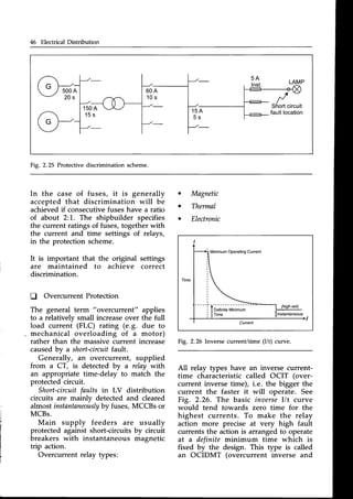
This chapter provides an overview of a ship's electrical system and distribution network. It outlines important safety considerations when working with electricity, such as preventing electric shock. The chapter describes various testing methods for circuits, such as insulation, continuity and diode testing. These tests are used to identify faults and ensure the safe operation of electrical equipment. General electrical maintenance and fault finding techniques are also covered to help crew properly service and repair shipboard electrical systems.


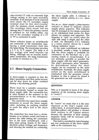
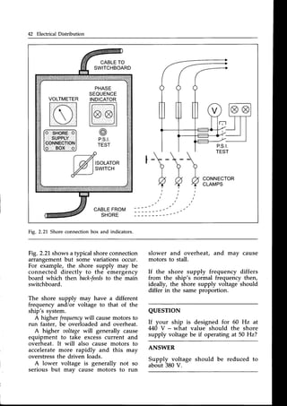
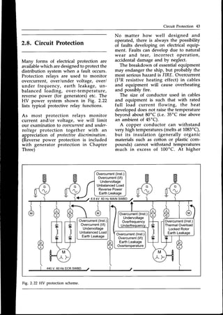
![Circuit Calculations 3
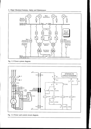
Large passenger ships usually have
four large generatorsrated at L0 MW or
more to supply the electric propulsion
motors and the extensive hotel services
on board. A cargo ship may have two
main generatorstypically rated from 350
to 1000kW which are sufficient to supply
the engine room auxiliaries while at sea
and the winches or cranes for handling
cargo while in port. The limited load
required during an emergency requires
that an emergency generator may be
rated from about 10 kW for a small
coaster to about 300 kW or more for
a cargo liner. The shipbuilder must
estimate the number and power rating
of the required generatorsby assessing
the power demand of the load for all
situations whether at seaor in port.
Electrical power on board ship is
commonly generated at 440 V, 60 Hz
(sometimes380 V, 50 Hz). Ships with a
very large electricalpower demand will
require generators that operate at a
high aoltage
(3.3kV, 6.6 kV or 11 kV) to
limit the size of normal load current and
the prospectivefault current.
The British Standard (BS) and Inter-
national ElectrotechnicalCommission
[EC) definition of.Iow aoltage
is 50 V a.c.
to 1000V a.c. (the IEC give this definition
to harmonise British and European
standards).
Lighting and other low power ancillary
services usually operate at 110 V or
220 V, single-phase a.c. Transformers
are used to reduce the 440 V svstem
voltage to these lower voltage leveis.
Where portable equipment is to be
used in dangerous, hot and damp
locations, it is advisable to operate at
55 V or even 24 V supplied again by a
step-down transformer. Occasionally,
transformers are also used to step-up
voltages, e.g. supplying a large 3.3 kV
bow thruster motor from a 440 V
switchboard supply.
Batteriesfor various essentialservices
operate at 1.2 V or 24 V d.c. but
sometimes higher voltages are used
if such loads require a large power
supply.
L.2. Circuit Calculations
The following gives
d.c. and a.c. circuits
a brief revision of
and calculations.
d.c. circuit
Rr = Rr + R2+ Re* . .., (in series)
1 1
* _ * - +. .. (in parallel)
R2 R3
Y: /.R (Ohms
Law)
Zemfs: Zpd's(Kirchhffi
Xlnv: Elour Kirchhffi
P : V . l : 1 2 . R
l = 1 , + 1 ,
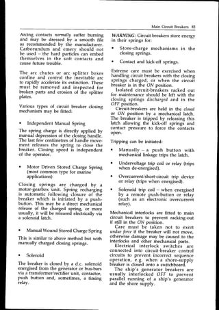
Example:
Using the above circuit with a 110 V d.c.
supply and R1 : 6 Q, Rz : 5 O, R3 : 5.5 O:
Calculate all currents, supply power and
p.d. acrossthe 6 O resistor.
Determineas.
11: 11.0/(6
+ 5) : 70A andlz : 110/5.5
: 20A
sosupplycurrenti, f- SOA,.
Supply
poweris P : V.I : 1"L0
. 30 : 3.3kW
fcheckutithP:Z(I'R)]
p.d. across6 Cl resistoris 11.6:1-0 . 6 : 60 V](https://image.slidesharecdn.com/practicalmarineelectricalknowledge2ed1999-211120130655/85/Practical-Marine-Electrical-Knowledge-2ed-1999-10-320.jpg)
![4 Ships' Electrical Systems, Safety and Maintenance
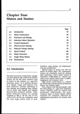
Example:
Using the above circuit with a
220 V, 60 Hz a.c. supply and R1 : 6 A,
Rz : 5 O, L : 0.1 H, C : 100lF:
Calculate all currents, supply power, overall
power factor and p.d. acrossthe 6 O resistor.
Determineas,
Xy:2.n.f.L= 37.7Q and X6= 7/2.n.f.C:26.5A
Then 21 : 38.2 Q at 81" Aagging)
and 22: 27 A at 79.3" (leading)
So, 11 : 220/38.2 : 5.76 A lagging V by 81"
and l, = 220/27: 8.1,5A leadingV by 79.3"
The total suryIy current is the phasorsum of
11and 12
which must be resoktedinto
"in-phase"
(hoizontal) and
"quadrature" (aertical)
components
beforeadding,
the result (for you to check)is l: 3.34 A
at 43.8" leading
Supply
PowerisP : 220.3.34.cos43.8"
: 531W
lcheckwith P: Z(l2R)]
OaeraIIpowerfactor is cos43.8": 0.72 leading
p.d. across6O : Ir . 6 : 5J6 . 6 -- 34.56V
three phase a.c. circuit
V7 : .l3.Vpp and ly : lpu 0n ST14R)
Vt: Vpu and Iy: '/3.1p11
Gn DELTA)
Ppu = Vp11.Ip11.cosS
: lr&.R
Balanced
3-phase:
P :'/ 3.VL.ly.cosg
Example:
Using the above circuit with a
M0 V, 3-phase, 60 Hz a.c. supply
and Za1: 10 O at p.f. = 0.8 lagging
(balanced load)
Calculate phase and line currents and supply
power when connected as:
(a) STAR and (b) DELTA
Determineas,
(a) in Star, Vpu : 440/J3 : 254 V
so Ippl'J
: 254/1-0: 25.4 A
and ly: lpu : 25.4A also
P : J3 .440
.2s.4
.0.8:1s.49
kw
(b) in Delta, Vpn: VL: 440 V
so lpp: 440/10 : 44 A
and l7: '/S.lE: 76.2A
P : "/3 . 440. 7G.2. 0.8 : 46.46 kw
(noticethis power is three times the
aalue in star)
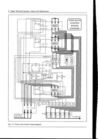
L.3 Electrical Diagrams
of diagram
an electrical
Singlephase a.c. circuit
I = l, ! l, (phasoraddition)
Xy: 2nfL @) X6: 1/2nfC@)
z : J R 4 x J o r z : J N + x j
l = V / Z
powerfactor
: cosQ: R/Z : PlS (lag or lead)
P : V.l.cos6or P : l2R (W)
Q: V.l.sinfor Q: l2x UAr)
S : V . l o r S : l 2 Z U A )
I
yr,l
V I
' t
v,l
I
There are various types
which attempt to show how](https://image.slidesharecdn.com/practicalmarineelectricalknowledge2ed1999-211120130655/85/Practical-Marine-Electrical-Knowledge-2ed-1999-11-320.jpg)


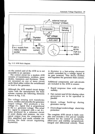
![Significance of Earth Faults 33
The generatorfull load current is:
t _
I L _
2,000,000 : 4 3 7 A
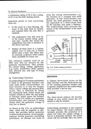
EXAI,IPLEINDICATION
o o o
EARTH FAULTON LINE 3
F t t r 5 l
L-
-]
lwtrcH
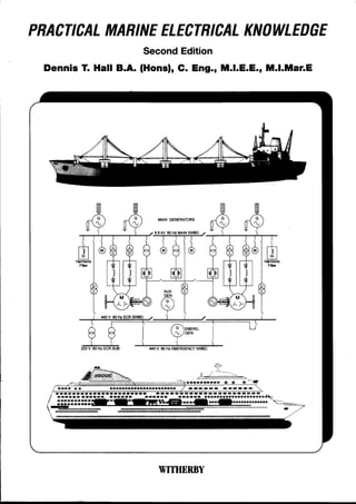
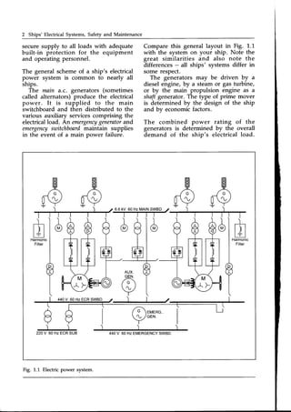
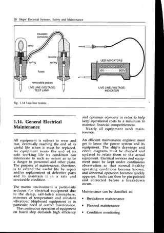
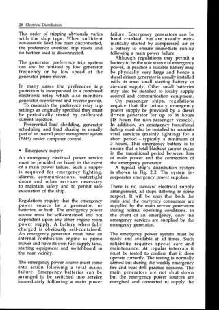
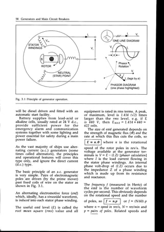
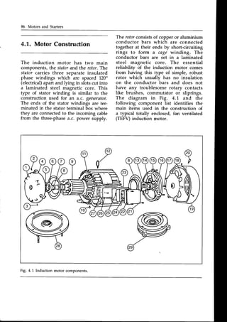
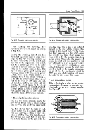
Fig.2.7 Earth fault monitoring with lamps.
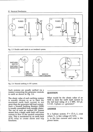
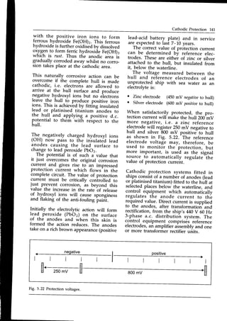
Earth indication lamps in a 3-phasea.c.
systemare arrangedasshown inFig. 2.7.
When the system is healthy (no earth
faults) then the lamps glow with equal
half brilliance. If an earth fault occurs
on one line, the lamp connected to that
line goes dim or extinguished. The other
lamps experience an increased voltage
so will glow brighter than before. Earth
indication lamps have been the most
common method used for many years,
being an inexpensive installation which
is easy to understand. Their major
disadvantage is that they are not very
sensitive and will fail to indicate the
presence of a high impedance earth
fault. This has led to the development
of instrument type earth fault indicators
which are being increasinglyused.
One common type of earth fault
instrument-type monitor connectsa small
d.c. aoltageto the distribution system.
Any resulting d.c. currentis a measureof
the insulation resistanceof the system.
The injection-type instrument limits the
maximum earth fault monitoring current
to only 1 mA (compared with about
60 mA for earth lamps), and the meter
indicates insulation resistance directly
in kO or MO. The monitor triggers an
alarm when its set value is reached.
This type of arrangement has been
developed to meet regulations which
demand that on tankers, for circuits in or
passing through hazardous zones, there
must be continuous monitoring of the
system insulation resistance.Visual and
v3. 3,300
. 0.8
Under EiF conditions a phase voltage of:
VpH:
=q
: 1905Vdrives the fault current
V 3
through the NER. So its ohmic value
has to b"r
1905
v : 4.4Q
437A
Certainessentialloads(e.g. steeringgear)
can be supplied via a transformer with
its secondary unearthed to maintain
security of supply in the event of a
sinele-earth fault.
Regulations insist that tankers have
ly insulated distribution syslems. This
intended to reduce danger from earth
ult currents circulating in the hull
ithin hazardous zones which may
use an explosion of the flammable
stem does not extend
gine room bulkhead
area.
ical supplies forward of the engine
bulkhead are usually 3-phaseM0 V
'r.oomDulKneaqare usuaily J-pnase++u v
insulatedand obtained from a 3-phase
3.3 kVlM0 V transformer.
Regulations require that an earth fault
monitor is fitted to the main switchboard
to indicate the presenceof an earth fault
on each isolatedsection of a distribution
system, e.g. on the 440 V and 220 Y
sections. An earth fault monitor can be
either a set of indicator lamps or an
instrument (calibrated in kf) or MO) to
show the system IR value to earth.
forward of the
and into the](https://image.slidesharecdn.com/practicalmarineelectricalknowledge2ed1999-211120130655/85/Practical-Marine-Electrical-Knowledge-2ed-1999-39-320.jpg)
![Significance of Earth Faults 35
I
]
I
t
An apparently simple method would
be to open the circuit-breakersfeeding
loads A, B, C, etc. one at a time and by
watching the earth fault monitor while
observing which circuit-breaker, when
tripped, clears the earth fault. The earth
fault must then be on that particular
circuit.
In practice, circuits cannot be dis-
connectedat random in this way. Some
vital service may be interrupted causing
the main enginesto stop ... perhapsin
dangerousnarrow waters.
Tracing the earth fault must be
co-ordinated with the operational
quirements of the ship's electrical
rvices. The method of earth fault
rancewill be described fullv for a
ting distribution circuit shown in
2.12.
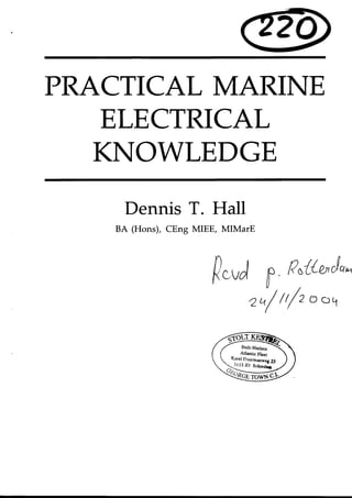
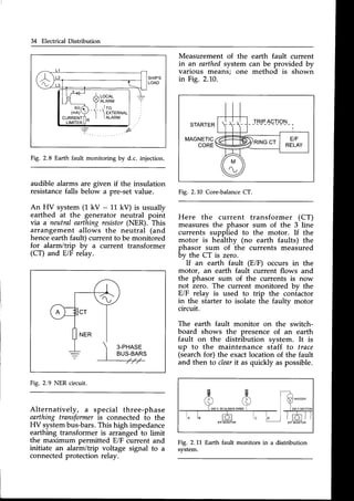
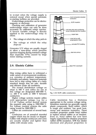
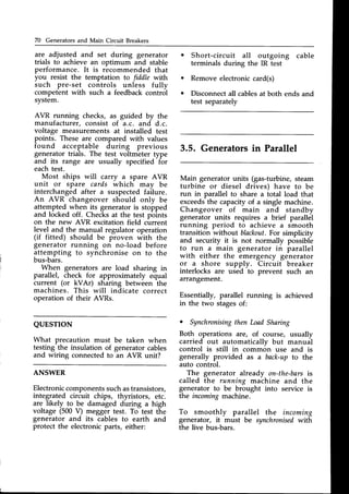
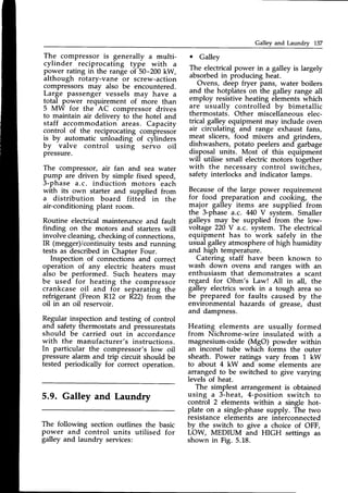
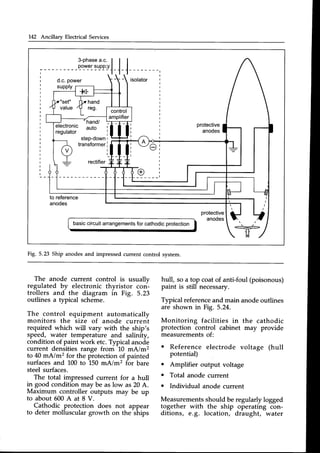
2.12 Threephaseto singlephasedistribution.
the earth fault monitor on the
lighting distribution board (d.b.)
the presenceof an earth fault.
witches A, B, C, are sequentially
pened and closed in turn until the earth
t monitor indicates the earth faulted
circuit. Supposethis is switch B.
Circuit B supplies a distribution fuse-
board (d.f.b.) located near its lighting
circuits. Here there is no earth fault
monitor so an IR (megger) tester must
be used.
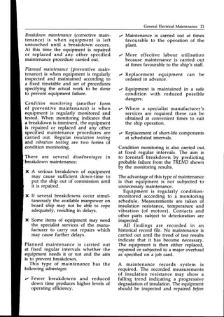
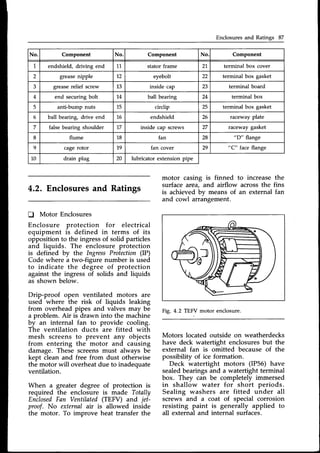
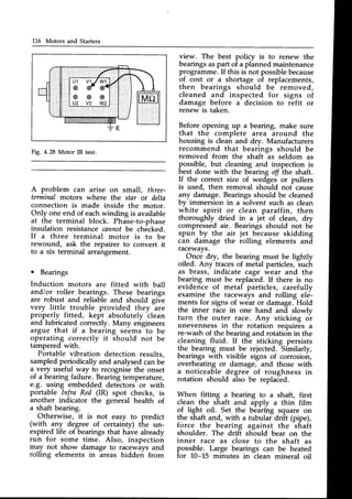
Fig. 2.13 TR testing at distribution fuse board.
At this d.f.b. fuse-pairNo. L is removed
to isolatethe supply to the load. (Fig.2.13)
The IR tester (megger) is now
connected with one lead to earth (hull)
and the other lead to "b" (the outgoing
terminal as shown), and a test applied.
If healthy (IR> 1 MO), connect the test
lead to
" a" arrd repeat the test. If both
" a" arrd "b" are healthy, circuit 1 is
healthy and fuse-pair 1 can be replaced.
Fuse-pair2 is now removed and tested
at " a" and "b" . If an earth fault is
indicated (IR : low) then the faulted
circuit has been located
All fuse-pairs are checked in turn to
confirm whether healthy or faulted.
At the faulted circuit, the fuses should
be removed, all switches should be
opened, and all lamps taken out as
shown in Fig. 2.14.
ccr 2 FUSESREMOVED SWITCH '
EFcleaLcdr
Fig. 2.14 IR test on a lighting circuit.
This breaks the circuit into several
isolated conductor sections.](https://image.slidesharecdn.com/practicalmarineelectricalknowledge2ed1999-211120130655/85/Practical-Marine-Electrical-Knowledge-2ed-1999-41-320.jpg)
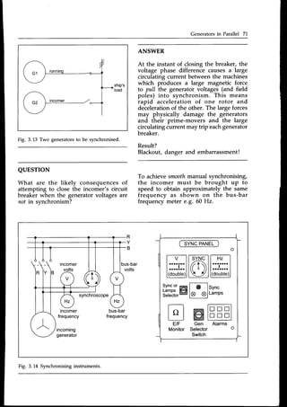
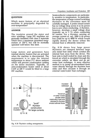
![lnstrument Transformers 39
3-PH220V
-
-
'--
iltflt ilrflr tll||l
ul ul |]i rlr rlr rlr
t t t t t l
i t t i i i
----1'NGL;;F.AS,
u."l-
LIGHTING
AND
LOWPOWERSUPPLIES
3 x 1-PHASE
TRANSFORMERS
CONNECTEDAS:
A-A
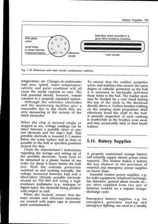
R 3-PH440V MAINSWITCHBOARD
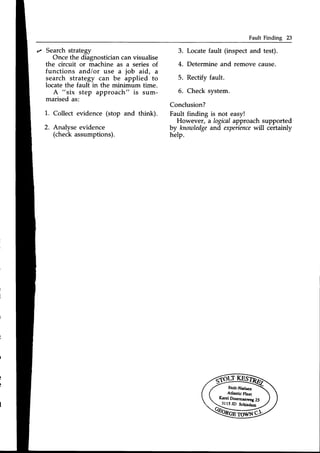
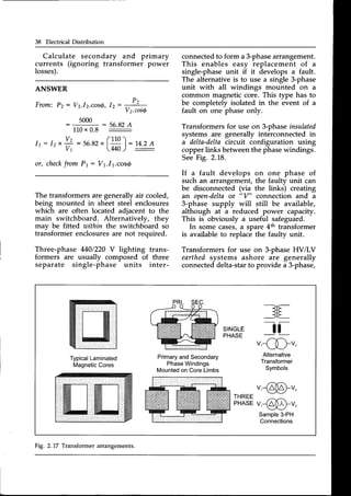
Fig. 2.18 Delta-deltatransformerconnection.
4-wire LV supply, e.g. a 6600/400V
ratio gives a secondary line voltage of
400V plus a line-neutral phase
voltage of
400/V3:230 V. An earth fault occurring
on a such neutral-earthed system will
immediately operate the prot-ective fuse
or circuit-breaker. This interruption of
supply leads to rapid identification of
the faulty circuit.
Transformers are static items of equip-
ment which are usually very reliable and
trouble-free. However, like all electrical
equipment, transformers must be sub-
jected to the usual maintenancechecks.
At regular specified intervals, trans-
formers must be disconnected, covers
removed and all accumulated dust and
deposits removed by " vacuum cleaner
and suitable brushes. Windings must
be inspected for any signs of damage
or over-heating. Winding continuity
resistancevalues are measured,recorded
and compared with each other for
balance. Anv differences in continuitv
readings will-indicate winding faults such
as short-circuited turns. The insulation
resistance of all windings must be
measured both with respect to earth and
to the other phase windings. The cause
of any low insulation resistance reading
must be investigated and rectified.
Cable connections must be checked for
tightness. Covers must be securely
replaced and the transformers re-
commissioned.
All testresultsand observationsshould
then be recorded for future reference.
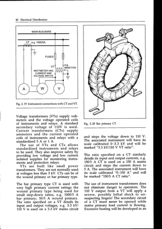
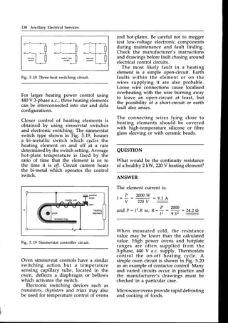
2.6. Instrument Transformers
Transformers are used to supply
instruments and protection relays with
proportionally smallcurrents and voltages
derived from the large currents and
voltages in a high power network. See
Fig.2.19.](https://image.slidesharecdn.com/practicalmarineelectricalknowledge2ed1999-211120130655/85/Practical-Marine-Electrical-Knowledge-2ed-1999-45-320.jpg)


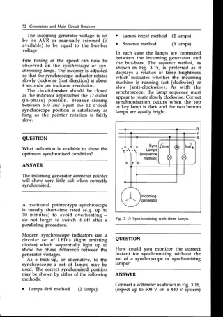
![AC GeneratorOperation Sg
pole-pairs
(p)
for 60 Hz
rea/min(N)
for 50 Hz
rea/min(N)
1 3600 3000
2 1800 1500
J 1200 1000
4 900 750
frequencieswith
F,"."yqber of pole_pairs
are given in the table below:
r The ratedvalues of a machine always
refer to line conditions 1us stuted or,
rating plate).
_.Angle @ is the phase angle between
Vpp and lpa which'is deternii""J Uy tnu
!yp"r_of electricalload on the generator
(e.g. lighting, motors, galley efrurpment
etc.).
,
C.ordi-slhe poToer
factorof the electrical
rolg.and is typically about 0.g laeeine
whrch means that the current *urrif6rrfi
lags about 37. behind the voltage.
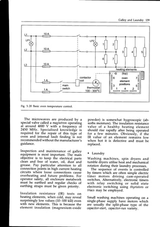
QUESTION
Il^" t9*"r,fu.l9r.metershownin Fig.3.2
nas rts scale divided into /or.rrsegments
- each calibrated0-1.0.'What'i, th"
significance of each segment?
ANSWER
An indication in the top half of the scale
shows that the .ma;h.ihe is _gin;rating.
The bottom half of the scale indicat8s
11"j
.*, generator is motoring.noth top
and bottom halves are fu-rther split
1119.
tug8ing and leading po*", factor
sections.
These two basic relationships for emf
a,nd frequency dictate how'to control
tne voltage and frequency output of a
generator. In practice ine speed is
maintained praciically constani bv the
generator's prime_mover whicn fixds ifre
.o;^?n^t,,11!uency.
The constant speed
rnen ailows the size of generated'emf
to,be directly controlled 6V tn" size of
pole ilux (excitation)
A- practical a.c. generator has three sets
of coils, called fhase windings, located
in slots in the stator surrou"nding the
rotating magneticpoles. The emf induced
rn each phase is 120" out of phase with
tne other two
.phas-es.Three_phase
windings
-are lab-elled as U_V_irywith
colour coding of red, yellow and blue
used on terminals and bus_bars.One
end of each of the three-phase*i"ai"g,
are joined together to form the neutral
potntor a starconnection.
The other ends of the phase windinss
are connected to outgoing conductois
called lines.
The three output line. voltages (repre_
sented by V.) and the 3 Sitput tine
currents (representedby l1) corirbine to
create the three_phaseelectrical power
output of:
P : J3.Vr.Ir.cos6watts
Fig. 3.2 Power factor meter.
Vy is m3deup from two p
In a star connection, arryline voltage
:]-:
-,1d" "gjlg- two pirase voltages,
voltage
whereVr: J3.Vpu.Th; Vs r;.?-i,
due to the 120. diiplacem"rrtb"t*""r,
phasevoltages.
e.g. if Vr:iiO-i, thrn
Vpu: 254V.](https://image.slidesharecdn.com/practicalmarineelectricalknowledge2ed1999-211120130655/85/Practical-Marine-Electrical-Knowledge-2ed-1999-64-320.jpg)

![Main Switchboard 79
thorough cleaning then dried out. If the
IR has recovered to a reasonablevalue
which has become steady during the
drying period, its windings should be
covered with high-quality air-drying
insulating varnish. Should the IR value
remain low during a dry-out, the machine
insulation needs to be completely re-
impregnated or rewound (generallyby a
specialistcontractor).
After maintenance, no-load running
checks should precede synchronising
and loading. On load, particularly check
for excesstemperature rise and load-
sharing stability when running in
parallel.
Finally, if a generator is to be left
idle or a long time, make sure that its
windings are suitably heated to prevent
internal condensation forming on its
insulation. As with all electrical equip-
ment - dirt, overheating and dampness
are the enemy!
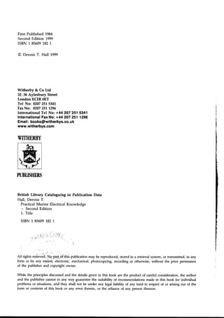
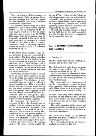
3.9. Main Switchboard
The central section of the main switch-
board is used for the control of the
main generators.The switchgearcubicles
on either side of the generator panels
are used for essential services and
flanking these are the grouped motor
starter panels.
Handles for opening the doors on
switchboard cubicles are usuallv linked
(or interlocked) to an isolating-switch.
This ensuresthat suppliesto components
in the cubicle are switched off before
the door can be opened.
Fused isolators are isolating switches
that incorporate fuses. The action of
opening the switch isolates the fuses
so that they can be replacedsafely.
Fused isolatorscan also be interlocked
with the cubicle door handle. Motor
starters frequently incorporate this
arrangement.
One type of interlocked fused isolator
can be completely withdrawn and
removed to ensurecompletesafetywhen
carrying out maintenanceon equipment.
Maintenanceon fused isolatorsconsists
of periodically checking the operating
mechanism. Contacts must be inspected
for damage and lightly greased with
an electrical lubricant. The interlock
mechanism (if fitted) should also be
examined for correct and safe operation.
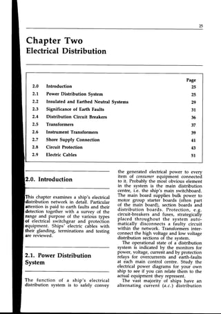
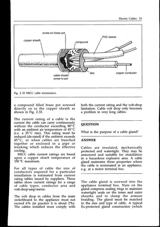
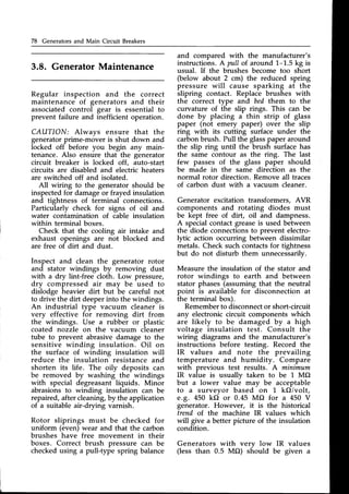
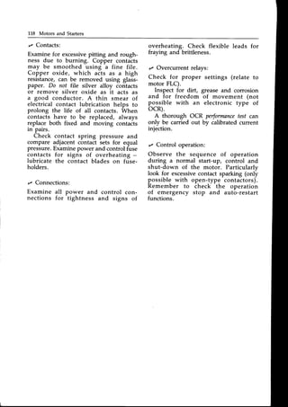
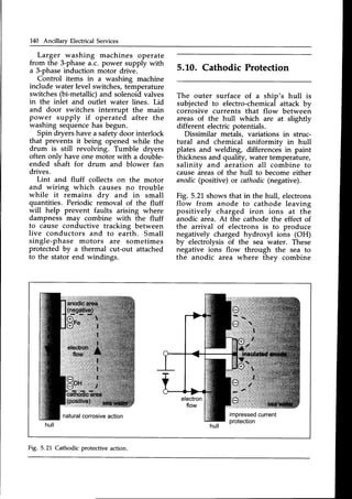
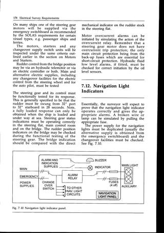
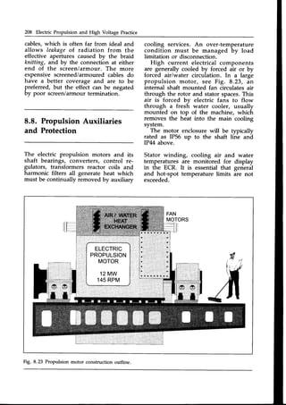
A typical layout of
switchboard is shown
a ship's main
in Fig. 3.19.
440V MainSwitchboard
Outline
nuutlo
Ut]U!
I
FF A-
- - - - l
l l
l l
l l
l -
- - - l
STARTERSSHORE TO
& FEEDERSSUPPY
EMERG
PORT SWBD
GEN1 BUS-TIEGEN2
(MAIN
BREAKERS
BEHIND)
TO SHORE
22OV SUPPY
SECT. STBD
STARTERS
& FEEDERS
220V
SECTION
FEEDERS
Fig. 3.19 Main switchboardlayout.](https://image.slidesharecdn.com/practicalmarineelectricalknowledge2ed1999-211120130655/85/Practical-Marine-Electrical-Knowledge-2ed-1999-84-320.jpg)


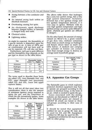
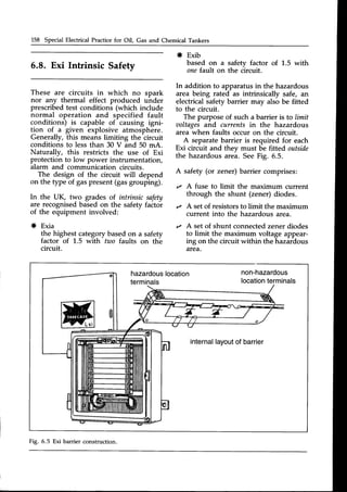
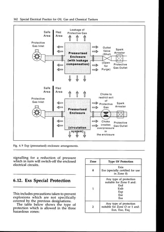
![164 special Electrical Practicefor oil, Gas and Chemical Tankers
QUESTTON
Explain the meaning of the Ex labellisted
above
ANSWER
Intrinsically safe (Exi) to the highest
safety factor (a) which is suitable for
installation in Zone 0. Apparatus group
(IIC) is suitable for hydrogen. Temp-
erature class (T4) allows a maximuh
surfacetemperature of 135'C.
The certifying authority is the UK test
house BASEEFA.
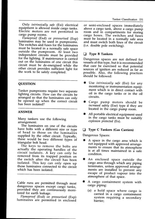
5.14. ElectricalTesting in
Hazardous Areas
All electrical apparatus and associated
circuits are required to be tested
periodically in accordancewith a definite
testing routine with recordedtest results.
Insulationresistance,
earthloop resistance
and earth continuity resistanie tests are
required to be made, the last two in
relation to the setting or rating of the
protective devices associated with the
apparatus and its circuitry.
It is important that insulation resistance
tests are NOT made in such a way that
the safety devices and insulation- used
in intrinsically safeapparatus and circuits
are damagedby excesstest voltages.
No apparatus should be opened in a
danger areauntil it has been made dead
and effective measures (e.g. locking-off
the isolating switch) have been tiken
to prevent- its being made live again
inadvertently.
Where, for the purpose of electrical
testing, it is necessary to restore the
power supply before the apparatus is
reassembled,testsshould be made using
a suitable gas detectorand continueii
during the operation to ensure that the
combustible does not approach the
explosive limit.
Unless the hazardous area can be
made gas-freeor otherwise safe, or the
electrical equipment is removed from the
area, then insulation resistance testing
should be carried out using a 500 V d.c]
t_esterof certified intrinsicilly safe (Exi)
design.
The.testing and maintenance of flameproof
or intinsically safeequipment shoulit be
entrusted only to competent persons
who have reieived ins^truction'in the
specialtechniquesinvolved.
The body material of instruments and
tools_qe_quired
for maintenancepurposes
should be designed so that they will not
make a hot spark when dropped.
The energyoutput of all intinsically safe
instruments should be so small that thdv
do not produce hot sparks.An insulation
tester has a droopingcharacteristic to
prevent -high currents and may be
intrinsically safe when applied to circuits
of small iriductance or ciairacitance
but a
risk may arise when suckienergy-storing
properties of a circuit have an aiirreciablE
value.
Where such instruments are used the
test leads should be firmly connected
throughout and on compl6tion of the
test they should not be detached until
the circuit has been discharged through
the testing instrument (leavi the testrer
for one minute after test is finished).
5.L5. Maintenance of
Ex-protectedApparatus
The previous sections covering zoning,
gas grouping, temperature classification
and the various types of protection
methodsshow that the designbf electrical](https://image.slidesharecdn.com/practicalmarineelectricalknowledge2ed1999-211120130655/85/Practical-Marine-Electrical-Knowledge-2ed-1999-168-320.jpg)

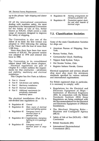
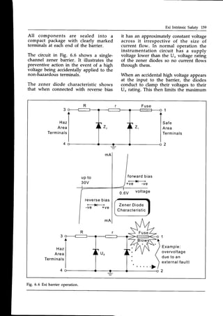
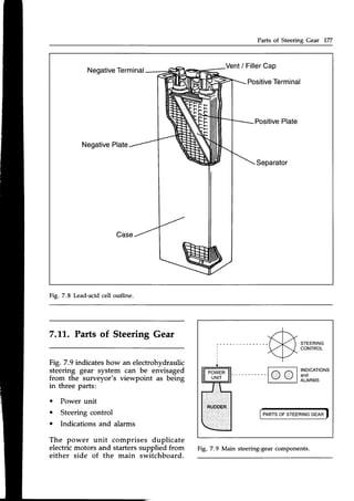
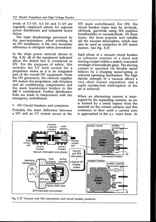
![172 Electrical Survey Requirements
moving the breaker from the service to
the isolated
position must be demonstrated
to be free moving and the fixed main
terminals must be seen to be shuttered
off when the breaker is withdrawn.
Emergency hand charging (if fitted) of
the closing spring will be tested. Correct
operation of the mechanical indicators
to show whether the breaker is open,
closed
or isolated,
is required.
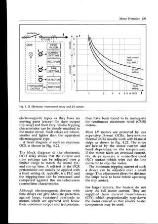
The underaoltage
release mechanism
and oaercurrenttrip settings for level and
time delay may have to be demonstrated
to the surveyor's satisfaction. An
overcurrent trip for a generator breaker
is typically set for 130% of full load
current (FLC) with a typical time delay
of 3 s, but this has to suit the thermal
capacity of the generator and be
co-ordinated with the overall protection
schemefor the power system.
Although the overcurrent and time delay
settings on the breaker can be seen to
be correctly adjusted to the desired
values, only a proper currentinjectiontest
will prove these settings against the
manufacturer's I/t characteristics.In this
test the circuit-breaker is isolated from
the bus-bar and a set of calibrated
currents from a current injection set
are fed directly through the closed
circuit-breaker (primary injection) or
(more usually) through the overcurrent
relay (secondary
injection).
This is generally
a specialisttask for an outside contractor.
Circuit-breaker time delav mechanisms
with oil dash pots must have the pots
filled to the correct level with clean
oil of a type recommended by the
manufacturer.
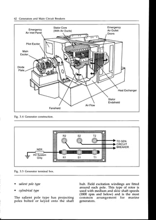
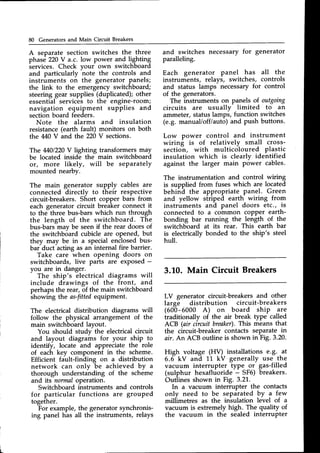
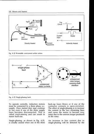
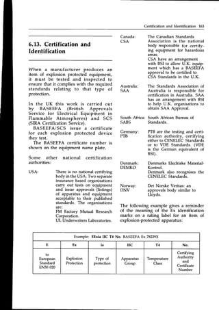
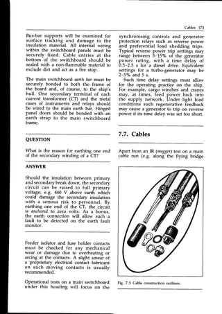
7.6. Switchboards and
Fittings
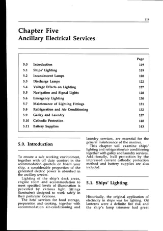
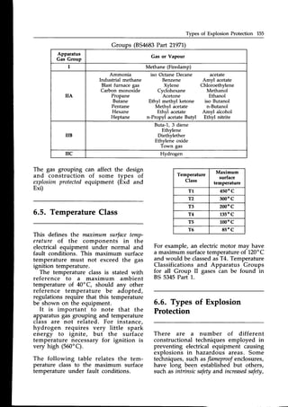
An obvious survey requirement for
any switchboard (as in Fig. 7.4), section
board or distribution board is that they
are clean. This includes all internal
surfaces as well as the external panel
surfaces, instrument faces and control
switches. A thorough cleaning job on
the inside of the main switchboard
can only be safely carried out when
the boird is completely dead (all
generators stopped and prime movers
locked-offl.
All the main bus-bar and auxiliarv
connections throughout the boardi
should be checked for tightness during
the deadperiod of a major internal clean
up. Overheating signs at a connection
junction are probably due to a loose
joint. Direct heat testing on load with an
infra-red thermal camera is now a very
useful technique for locating hot-spots.
440V MainSwitchboard
Outline
NUUU(]
"tr?!
E O =
I :,.:.,::i,:
l . l l . , ' . 1
" ' J
t,.
I .,....',
,:.,1
L : : : : , : , : : . . : : . . . 1
li ..: ii-4...1
N o
troo
N o
E o o
STARTERS SHORE TO
& FEEDERS SUPPYEMERG
PORT SWBD
GEN1 BUS-TIE GEN2
(MAIN
BREAKERS
BEHIND)
TO
220V
SECT.
SHORE
SUPPY
STBD
STARTERS
& FEEDERS
220V
SECTION
FEEDERS
Fig. 7.4 Main switchboard arrangement.](https://image.slidesharecdn.com/practicalmarineelectricalknowledge2ed1999-211120130655/85/Practical-Marine-Electrical-Knowledge-2ed-1999-176-320.jpg)

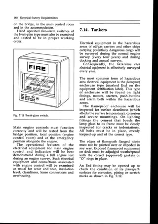
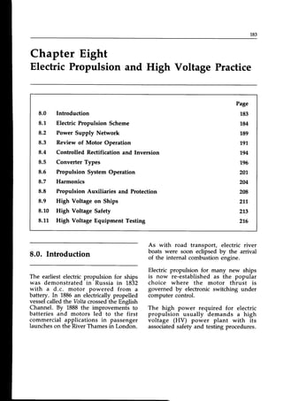
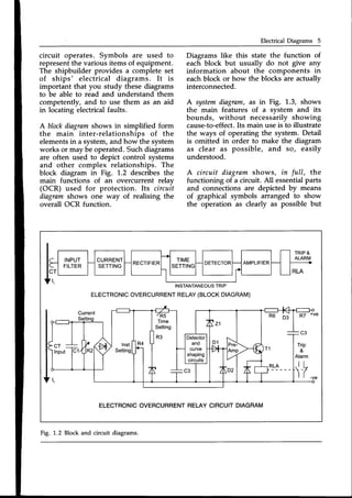
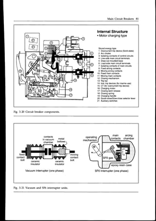
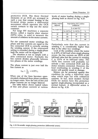
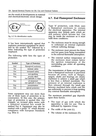
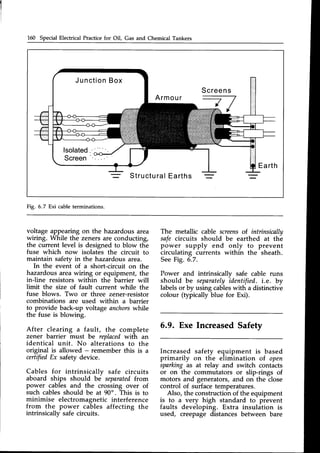
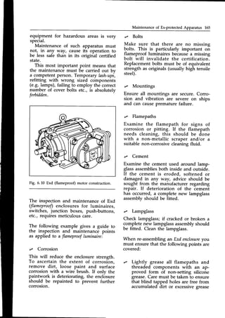
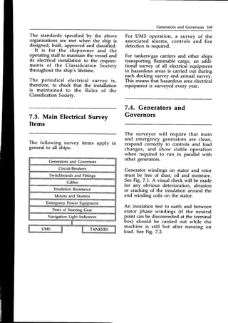
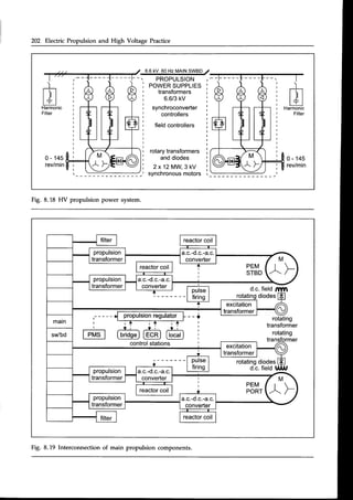
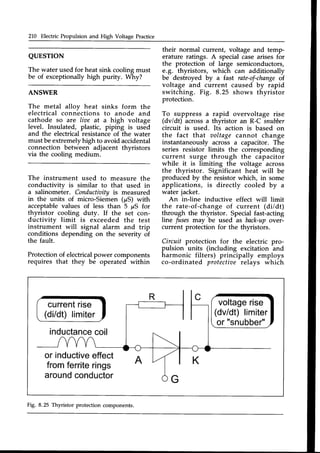
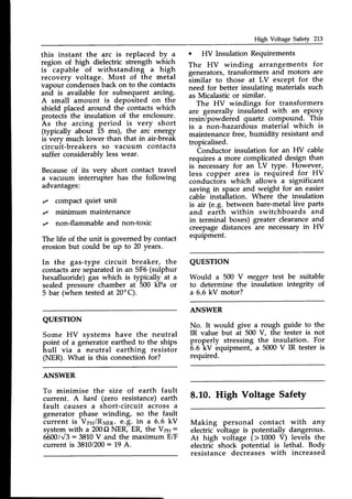
![Electric Propulsion Scheme L85
a
o
a
Economical part-load running
Easeof control
Low noiseand vibration characteristics
Flexibility of layout
The advantageof an electric transmission
is that the prime-movers, and their
generators, are not constrained to have
any particular relationship with the
load as a cable run is a very versatile
transmission medium. In a ship pro-
pulsion system it is possible to mount
the diesel engines, gas turbines etc.,
in locations best suited for them and
their associatedservices,so they can be
ECR
HVmimic
-l
I tr r:-r n l
engineconsole
propulsion
computer
localcontrol
position
propulsion
computer
PEMl
6.6kV (HV)
switchboard
440V
engineroom
switchboard
DECK4
DECK3
DECK2
Engine
Control
Room
- - t
converterl I
transformer
@
"onu"rt"r[l]l
"onu"rt"'.lLlltj
transformer
Cf)
o.c.
O
coilsO
propulsion
electric
motors
transformer
converter d'.,O a7r|
6qilsrl )L/
transformer
diesel- gensets
Fig. 8.2 Propulsion plant layout.](https://image.slidesharecdn.com/practicalmarineelectricalknowledge2ed1999-211120130655/85/Practical-Marine-Electrical-Knowledge-2ed-1999-188-320.jpg)
![Converter Types 199
I
I
I
I
I
I
I
I
I
'DC
- +
rc
rr,/$1ffi----@ffi1
w
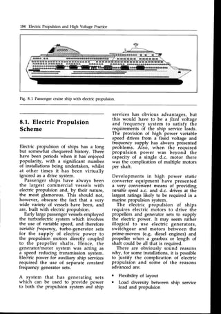
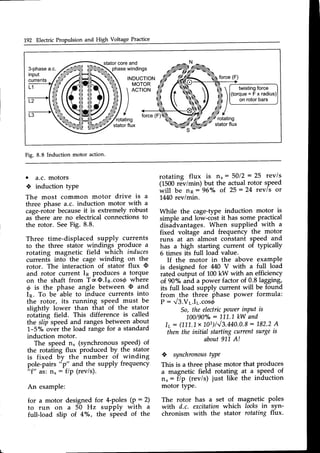
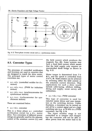
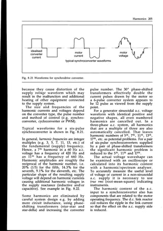
Fig. 8.L6 Inverter current switching sequence.
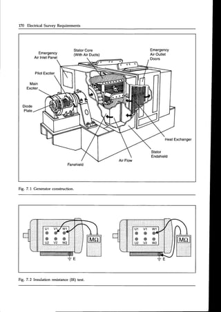
This view considers the rectifier stage
as a controlled d.c. supply and the
inverterisvnchronous motor combination
as a d.c. motor. The switching inverter
acting as a static commutator.
The combination of controlled rectifier
and d.c. link is considered to be a
currentsourcefor the inverter whose task
is then to sequentially direct blocksof
the current into the motor windings
as shown in Fig. 8.16.
T]l.e size of the d.c. current is set bv
the controlled switching of the rectifier
thyristors. Motor supply frequency(and
hence its speed) is set by the rate of
inverter switching. The six inverter
thyristors provide six current pulses
per cycle (known as a six-pulse
converter).
A simplified understanding of syn-
chroconverter control is that the current
source (controlled rectification stage)
provides the required motor torque and
the inverter stage controls the required
speed.To provide the motor e.m.f. which
is necessary for natural commutation
of the inverter thyristors, the synchronous
motor must have rotation and magnetic
flux in its rotor poles. During normal
running, the synchronous motor is
operated with a power factor of about
0.9 leading (by field excitation control)
to assist the line commutation of the](https://image.slidesharecdn.com/practicalmarineelectricalknowledge2ed1999-211120130655/85/Practical-Marine-Electrical-Knowledge-2ed-1999-202-320.jpg)
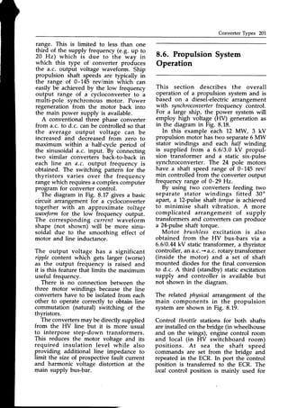
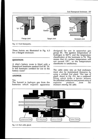
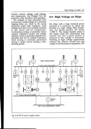
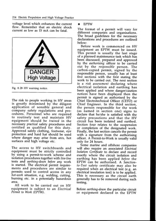
![Propulsion System Operation 203
COMPUTER
CONTROL
REGULATOR
P M S
SHAFTPOSITION
SPEED
INPUT
SHAFTSPEED:
i
3-pha.c.
3kV 60Hz
3-pha.c.0-3kV
0-29
0-145
RPM
PROPULSION
MOTOR
NETWORK
BRIDGE
CONTROL,LED
RECTIFIER
MACHINE
BR.]DGE.
CONTROLLED
INVERTER
SYNCHRODRIVE
CONVERTER
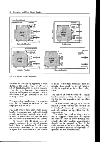
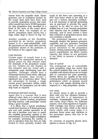
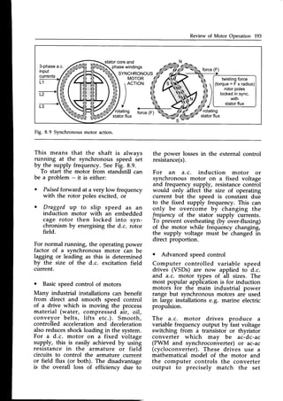
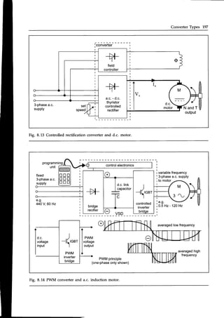
Fig. 8.20 Propulsion motor control scheme.
testing and maintenanceduties but also
acts as an emergency control station.
Selection of the command position is
determinedby a switch on the propulsion
consolein the ECR.
An emergency push-button telegraph
giving sef speed commands (dead-slow,
half-ahead etc.) is available at each
control station. The ship propulsion
regulator and side-thrusterregulatorscan
be combined into a master iou-stick
controller to give overall direitional
control for accurate manoeuvring in
port.
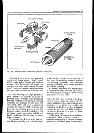
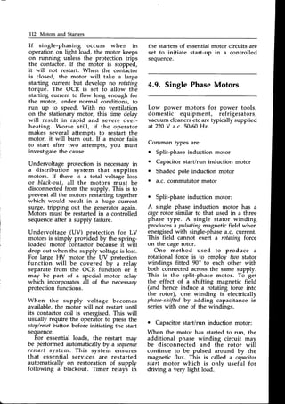
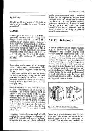
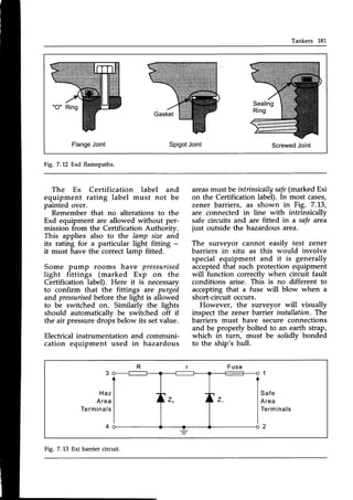
In a synchrodrive system as shown
in Fig. 8.20, the computer receivesa
command (set speed) input and many
feedbacksignals(voltage,current, power,
frequencyetc.)but the obviousregulating
item is the actual shaft speed feedback
forming a closedcontrol loop. The prin-
cipal parameters to be controlled are
the size of motor stator current (to set
motor torque) and the motor frequency
to set the shaft speed. In addition,
the d.c. motor field current has to be
continually controlled from the pro-
pulsion regulator via the excitation
converter.
In normal running and full-away with
both propulsion motor speeds within
5o/oof each other, the bridge can select
a shaftsynchro-phasing
mode which applies
momentary acceleration/decelerationto
bring the propeller blades into an align-
ment which minimises shaft vibration
into the hull.
Speed and position are derived from
detectors on the non-drive end of the
motor shaft.
At speedsof lessthan 10%, the motor
does not generate sufficient backe.rn.f.
to cause automatic thvristor switch-off
(line commutation) Remember that a
thvristor can only switch off when its
current becomes zero. This problem is
overcome by pulse-mode
operation where
the current is momentarilv forced to zero
by the thyristors in ine controlled
rectifier stage. This allows the inverter](https://image.slidesharecdn.com/practicalmarineelectricalknowledge2ed1999-211120130655/85/Practical-Marine-Electrical-Knowledge-2ed-1999-206-320.jpg)


![222 Index
| (contd.)
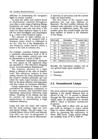
IncandescentLamps 120
IncreasedSafety Exe 150
Induction Motor Operation 90
Infra Red Image Testing 116, 172, 217
Ingress Protection (IP Code) 88
Instrument Transformers 39
Insulated Neutral System 29
Insulation Class 12
Insulation Resistance(IR) Survey 174
Insulation ResistanceLL
Insulation Testing 13
Interference (Noise) 207
Intrinsic Safety Exi 158, 181
Inversion 195
L
Lamp Types 120
Laundry Equipment 139
Lead-acidBattery 145
Live-Line Testers 19. 215
Load Sharing between Generators 74
Low Location Lighting (LLL) 131
M
Main Circuit Breakers 80, 17L
Main Supply 26
Main Switchboard 79, 172
Maintenance of Ex Apparatus 164
Maintenance of Generators 78
Maintenance of Lighting Fittings 131
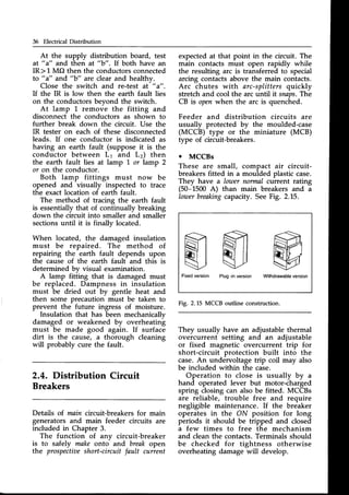
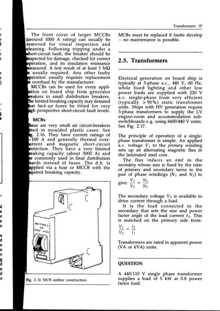
MCCBs and MCBs 36
Micro-ohmmeter 217
Motor and Starter Maintenance 114
Motor Braking 204
Motor Construction 86
Motor Enclosuresand Ratings 87
Motor Operation 90, 19L
Motor Protection 105, 210
Motor Speed Control 100, 193
Motor Starting 92, 793
Motors and Starters Survey 175
Multimeters 16
N
Navigation and Signal Lights 128
Navigation Lights Survey 178
Non-Sparking Exn 161
o
Overcurrent Protection (OCR) 45, 707,270
P
P.I. (PolarisationIndex) 217
Parallel Operation of Generators 70
Permit to Work 214
Planned Maintenance 20
Power Distribution System 25
Power Factor 59
Power Management System (PMS) 204
Power Supply for Electric Propulsion 189
PreferenceTripping 28
PressurisedEnclosure Exp 761, 787
Propulsion Motor Types and Operation 191
Protection of Motors 105. 210
Protection of Generators 75
Protective Discrimination 45
Pulse-mode Operation 204
PWM Converter 198
R
Rectification 194
Reduced Voltage Starting 95
Refrigeration Equipment 132
RegenerativeBraking 204
ReversePower Protection Z
s
Safety 9, 213
Shaded-poleMotor 113
Shaft Generator Operation 60
Ship Electric Propulsion Scheme 184
Ships Electrical System 1
Ships Lighting 119
Shore Supply Connection 41
Simmerstat Control 138
Single PhaseMotor Types 112
Single-phasing Protection 1L0
Smoke and Fire Detection 179
Sodium Vapour Lamps 126
Soft Starting of Motors 99
SOLAS Regulations 167
Special Protection Exs 162
Split-phase Motor 112
Star-Delta Starter 95
Steering Gear Survey 177
Superconductivity 189
Survey (Electrical)Items 169
Switchboards Suwey 172
Synchroconverter 198
Synchronising of Generators 70
Synchronous Motor Operation 192, 201
T
Tanker Classification 150
Tanker Suwey (Electrical) 180
Temperature Sensors 109
Testing in Hazardous Areas 164
THD 206
Three-heat Switching 137
Thyristor Cooling and Protection 209
Thyristor 704,795
Transformers 37
Transistor ].04' 198
U
LIMS Operation Survey 179
Undervoltage Protection 50
UPS Systems 737, 747
v
Vacuum and SF6Intemrpters 80,272](https://image.slidesharecdn.com/practicalmarineelectricalknowledge2ed1999-211120130655/85/Practical-Marine-Electrical-Knowledge-2ed-1999-224-320.jpg)


![[5] ptk 2014 2015 ship main particulars](https://cdn.slidesharecdn.com/ss_thumbnails/yeag3dqqteyakhmw8drg-signature-e54dc48fc8dff231a3667ed370712382aa80c6605f7be8d156fba02fb451e6f5-poli-141027141818-conversion-gate02-thumbnail.jpg?width=640&height=640&fit=bounds)


