Downloaded 199 times

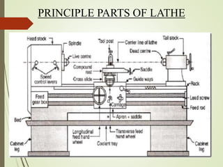
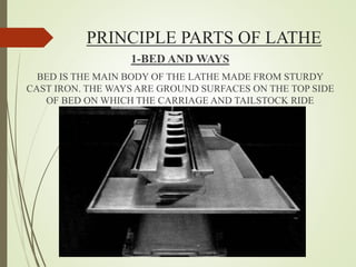
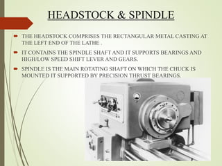
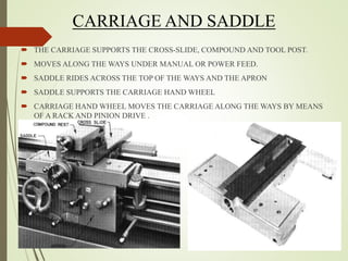

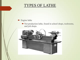
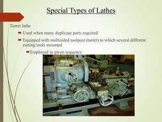
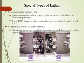
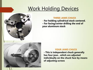
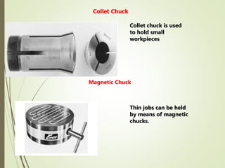
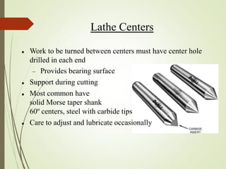
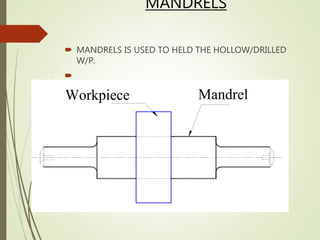
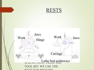
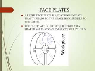
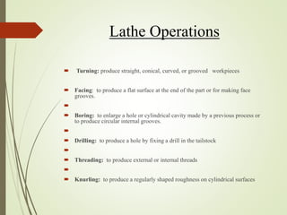
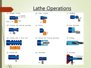
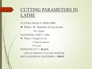

The document discusses the principle parts and operations of a lathe machine tool. It describes the main components of a lathe including the bed, headstock, spindle, carriage, saddle, cross-slide, compound, toolpost, and tailstock. It explains different types of lathes and work holding devices. Finally, it outlines common lathe operations such as turning, facing, boring, drilling, threading, and knurling as well as cutting parameters for machining on a lathe.


