The document discusses the requirements and components of a clutch mechanism. It provides details on:
1. The key requirements of a clutch include transmitting maximum engine torque without slippage, dissipating large amounts of heat generated, engaging gradually without jerks, being dynamically balanced, damping vibrations, having minimum inertia when disengaged, and requiring minimal force to disengage.
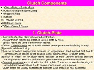
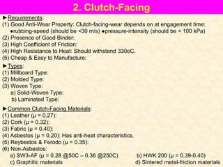
2. The main components of a clutch are the clutch plate, friction facings, pressure plate, springs, throwout bearing, and release levers. The clutch plate transfers torque via friction facings attached to its steel plate. The pressure plate applies pressure to the clutch plate via springs.
3. Different types of clutches include single