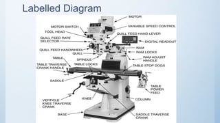
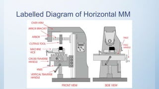
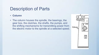
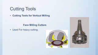
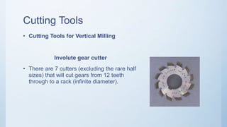
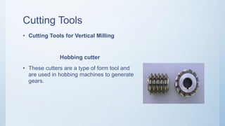
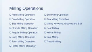
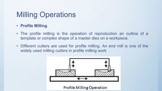
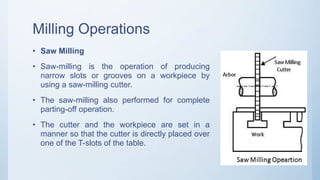
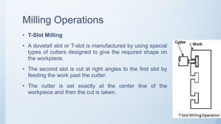
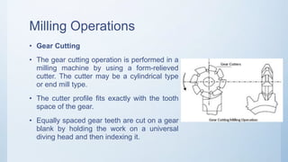
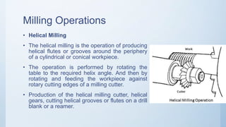
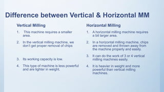
3. Milling Process
• Milling Process
• Milling is the process of machining using rotary cutters to remove
material by advancing a cutter into a work piece.
• This may be done varying direction on one or several axes, cutter
head speed, and pressure.
4. Milling Machine
• Milling Machine
• A device that rotates a circular tool that has a number of cutting
edges symmetrically arranged about its axis.
• The workpiece is commonly held in a vise or similar device clamped to
a table that can move in three perpendicular directions.
8. Horizontal Milling Machine
• Milling head can be adjusted manually by 45 degree
• The spindle sleeve can be manually micro-injected
• Workable X,Y,Z three way monetarized speed
• The rectangular guide rail has good strength and stability
• Has less accuracy
10. Parts of Horizontal Milling Machine
1. Column
2. Knee
3. Saddle
4. Table
5. Arbor
6. Base
7. Spindle
8. Spindle Reverse Lever
9. Spindle Speed Selection Lever
10. Spindle Clutch Lever
11. Feed Rate Selection Lever
12. Motor Start and Stop Buttons
11. Description of Parts
• Column
• The column houses the spindle, the bearings, the
gear box, the clutches, the shafts, the pumps, and
the shifting mechanisms for transmitting power from
the electric motor to the spindle at a selected speed.
12. Description of Parts
• Knee
• Knee is the first moving part of milling
machine. If is mounted on the column and
moves along the slideways situated over the
column. It is made by cast iron and moves
vertically on slideways It moves up and down
on sideways which change the distance
between tool and workpiece It is driven by
mechanically or hydraulically.
13. Description of Parts
• Saddle
• The saddle consists of two slideways, one on
the top and one at the bottom located at 90º to
each other, for providing motions in the X or Y
axes by means of lead screws.
• The main function of it is to provide motion in
horizontal direction to work piece
14. Description of Parts
• Table
• The table is mounted on top of the saddle and can be moved
along the X axis. On top of the table are some T-slots for the
mounting of workpiece or clamping fixtures.
• It can provide three degree of freedom to work piece.
It provides vertical motion by moving the knee up and down.
It provides horizontal motion by the feed screw.
It provides horizontal (transverse) motion by moving the saddle.
15. Description of Parts
• Arbor
• It is a mechanical part on which is used as
extension part of the spindle in horizontal milling
machine. It is fitted on the spindle whenever
required. It holds the tool and moves it in correct
direction.
16. Description of Parts
• Arbor Support
• This are used to support arbor at right place. One end of this support is
jointed at the overhanging arm and another is jointed with arbor.
17. Description of Parts
• Spindle
• The spindle holds the tool and provides the actual tool rotation.
• It is motor driven and drives the tool. It has a slot on the front end of it.
The cutting tool fix in that slot.
18. Description of Parts
• Spindle Reverse Lever
• The position of this lever determines the spindle direction. The three
positions of the handle are,
– In
– Middle
– Out
• The middle position is the neutral position. Never move the spindle
reverse lever when the spindle is turning.
19. Description of Parts
• Overhanging arm
• It is situated over the column on horizontal milling machine. It is
overhang over the column surface and other end supports the arbor. It
is made by cast iron.
20. Description of Parts
• Spindle Speed Selection Lever
• The spindle speed selection lever is used to change the spindle R.P.M.
setting. This type of machine has a geared head so the spindle speed
can only be changed when the spindle is stopped.
21. Description of Parts
Spindle Clutch Lever
• The spindle clutch lever engages the spindle clutch to the motor. By
manipulating the spindle clutch lever the operator can start and stop
the spindle.
22. Description of Parts
• Feed Rate Selection Lever
• The feed rate selection lever is used to change the feed rate setting.
The feed rate settings are expressed in inches per minute.
23. Description of Parts
• Motor Start and Stop Buttons
• The motor start and stop buttons control the power to the main motor
for the machine
24. Vertical Milling Machine
• The vertical milling machine is a precision tool used for shaping and
fabrication by the removal of stock typically from metallic work pieces.
• Workable X,Y,Z three way monetarized speed
• The rectangular guide rail has good strength and stability
• Has more accuracy
26. Parts of Vertical Milling Machine
• vertical milling machine which is of similar construction to a horizontal
milling machine except that the spindle is mounted in the vertical
position
• It’s additional features are:
Milling Head
Ram
27. Description of Parts
• Milling Head
• The milling head consisting the spindle, the motor, and the feed control
unit is mounted on a swivel base such that it can be set at any angle to
the table.
28. Description of Parts
• Ram
• The ram on which the milling head is attached can be positioned
forward and backward along the slideway on the top of the column.
29. Cutting Tools
• Cutting Tools for Horizontal Milling
Slab Mills
• For heavy cutting of large and flat
surfaces.
30. Cutting Tools
• Cutting Tools for Horizontal Milling
Side and Face Cutters
• This type of cutters has cutting edges on
the periphery and sides of the teeth for
cutting shoulders and slots
31. Cutting Tools
• Cutting Tools for Horizontal Milling
Slitting Saws
• For cutting deep slots or for parting off.
32. Cutting Tools
• Cutting Tools for Vertical Milling
End Mills
• Commonly used for facing, slotting and
profile milling.
33. Cutting Tools
• Cutting Tools for Vertical Milling
Rough Cut End Mills
• For rapid metal removal.
34. Cutting Tools
• Cutting Tools for Vertical Milling
Slot Drills
• For producing pockets without drilling a
hole before hand.
35. Cutting Tools
• Cutting Tools for Vertical Milling
Face Milling Cutters
• Used For heavy cutting.
36. Cutting Tools
• Cutting Tools for Vertical Milling
Involute gear cutter
• There are 7 cutters (excluding the rare half
sizes) that will cut gears from 12 teeth
through to a rack (infinite diameter).
37. Cutting Tools
• Cutting Tools for Vertical Milling
Hobbing cutter
• These cutters are a type of form tool and
are used in hobbing machines to generate
gears.
39. Milling Operations
• Plain Milling
• Plain milling is the milling of a flat surface with the axis of the cutter
parallel to the machining surface. It can be carried out either on a
horizontal machine or a vertical machine.
40. Milling Operations
• Face Milling
• The face milling is the simplest milling machine
operations.
• This operation is performed by a face milling cutter
rotated about an axis perpendicular to the work
surface.
• The operation is carried in plain milling, and the
cutter is mounted on a stub arbor to design a flat
surface.
• The depth of cut is adjusted by rotating the
crossfeed screw of the table.
41. Milling Operations
• Side Milling
• The side milling is the operation of producing a flat vertical surface on
the side of a workpiece by using a side milling cutter.
• The depth of cut is set by rotating the vertical feed screw of the table.
42. Milling Operations
• End Milling
• End Milling is the milling of a flat surface with the axis of the cutter
perpendicular to the machining
43. Milling Operations
• Gang Milling
• Gang milling is a horizontal milling operation that utilizes three or
more milling cutters grouped together for the milling of a complex
surface in one pass. As illustrated in figure 18, different type and size
of cutters should be selected for achieving the desire profile on the
workpiece.
44. Milling Operations
• Straddle Milling
• In straddle milling, a group of spacers is mounted in between two
side and face milling cutters on the spindle arbor as shown in figure
19. for the milling of two surfaces parallel to each other at a given
distance.
45. Milling Operations
• Angular Milling
• The angular milling is the operation of producing
an angular surface on a workpiece other than at
right angles of the axis of the milling machine
spindle.
• The angular groove may be single or double angle
and may be of varying included angle according to
the type and contour of the angular cutter used.
• One simple example of angular milling is the
production of V-blocks.
46. Milling Operations
• Form Milling
• The form milling is the operation of producing the
irregular contour by using form cutters.
• The irregular shape may be convex, concave, or of
any other shape. After machining, the formed
surface is inspected by a template gauge.
• Cutting rate for form milling is 20% to 30% less than
that of the plain milling
47. Milling Operations
• Profile Milling
• The profile milling is the operation of reproduction an outline of a
template or complex shape of a master dies on a workpiece.
• Different cutters are used for profile milling. An end mill is one of the
widely used milling cutters in profile milling work
48. Milling Operations
• Saw Milling
• Saw-milling is the operation of producing
narrow slots or grooves on a workpiece by
using a saw-milling cutter.
• The saw-milling also performed for complete
parting-off operation.
• The cutter and the workpiece are set in a
manner so that the cutter is directly placed over
one of the T-slots of the table.
49. Milling Operations
• T-Slot Milling
• A dovetail slot or T-slot is manufactured by using special
types of cutters designed to give the required shape on
the workpiece.
• The second slot is cut at right angles to the first slot by
feeding the work past the cutter.
• The cutter is set exactly at the center line of the
workpiece and then the cut is taken.
50. Milling Operations
• Gear Cutting
• The gear cutting operation is performed in a
milling machine by using a form-relieved
cutter. The cutter may be a cylindrical type
or end mill type.
• The cutter profile fits exactly with the tooth
space of the gear.
• Equally spaced gear teeth are cut on a gear
blank by holding the work on a universal
diving head and then indexing it.
51. Milling Operations
• Helical Milling
• The helical milling is the operation of producing
helical flutes or grooves around the periphery
of a cylindrical or conical workpiece.
• The operation is performed by rotating the
table to the required helix angle. And then by
rotating and feeding the workpiece against
rotary cutting edges of a milling cutter.
• Production of the helical milling cutter, helical
gears, cutting helical grooves or flutes on a drill
blank or a reamer.
52. Milling Operations
• Cam Milling
• The cam milling is the operation of producing cams in a milling machine
by the use of universal dividing head and a vertical milling attachment.
The cam blank is mounted at the end of the dividing head spindle and an
end mill is held in the vertical milling attachment.
• The axis of the cam blank and the end mill spindle should always remain
parallel to each other when setting for cam milling. The dividing head is
geared to the table feed screw so that the cam is rotated about its axis
while it is fed against the end mill. The axis of the cam can be set from 0
to 90° in reference to the surface of the table for obtaining a different rise
of the cam.
53. Milling Operations
Thread Milling
• The thread milling machine operations are used to produce threads by
using a single or multiple thread milling cutter. Thread milling operation
is performed in special thread milling machines to produce accurate
threads in small or large quantities.
• The operation requires three driving motions in the machine. One for the
cutter, one for the work and the third for the longitudinal movement of the
cutter
54. Difference between Vertical & Horizontal MM
Vertical Milling
1. In a vertical milling machine, a
spindle axis is aligned vertically
2. It is cheaper in price.
3. We get a poorer surface finish.
4. Vertical milling machine reduces the
tool life
Horizontal Milling
1. Here, a spindle axis is placed in a
horizontal direction.
2. A horizontal milling machine is a little
bit costly.
3. By using a horizontal milling machine,
you will get the best surface finishing.
4. Horizontal Milling Machines help to
increase the tool life.
55. Difference between Vertical & Horizontal MM
Vertical Milling
1. This machine requires a smaller
area.
2. In the vertical milling machine, we
don’t get proper removal of chips
3. Its working capacity is low.
4. This type of machine is less powerful
and are lighter in weight.
Horizontal Milling
1. A horizontal milling machine requires
a bit larger area.
2. In a horizontal milling machine, chips
are removed and thrown away from
the machine properly and easily.
3. It can do the work of 3 or 4 vertical
milling machines easily.
4. It is heavier in weight and more
powerful than vertical milling
machines.
56. Which is Better?
• In short,
• vertical milling machines are versatile and mostly used
• Horizontal milling machine is perfect for high-cheap removal work,
high-horsepower and a heavy-duty.