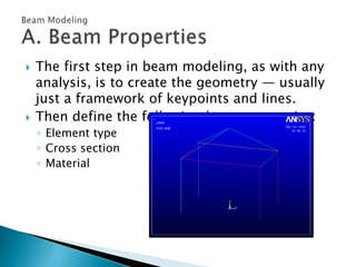
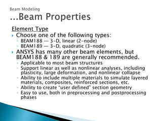
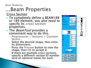
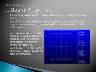
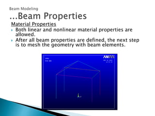
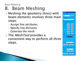
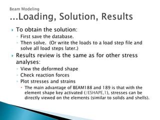
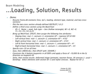
 Beam elements are line elements used to
create a one-dimensional idealization of a 3-
D structure.
 They are computationally more efficient than
solids and shells and are heavily used in
several industries:
◦ Building construction
◦ Bridges and roadways
◦ People movers (trams,
railcars, buses)
◦ Etc.
 A brief introduction to beam modeling via the
following topics:
A. Beam Properties
B. Beam Meshing
C. Loading, Solution, Results
 The first step in beam modeling, as with any
analysis, is to create the geometry — usually
just a framework of keypoints and lines.
 Then define the following beam properties:
◦ Element type
◦ Cross section
◦ Material
Element Type
 Choose one of the following types:
◦ BEAM188 — 3-D, linear (2-node)
◦ BEAM189 — 3-D, quadratic (3-node)
 ANSYS has many other beam elements, but
BEAM188 & 189 are generally recommended.
◦ Applicable to most beam structures
◦ Support linear as well as nonlinear analyses, including
plasticity, large deformation, and nonlinear collapse
◦ Ability to include multiple materials to simulate layered
materials, composites, reinforced sections, etc.
◦ Ability to create “user defined” section geometry
◦ Easy to use, both in preprocessing and postprocessing
phases
Cross Section
 To completely define a BEAM188
or 189 element, you also need to
specify its cross section
properties.
 The BeamTool provides a
convenient way to do this.
◦ Preprocessor > Sections > Common
Sectns...
◦ Select the desired shape, then enter
its dimensions.
◦ Press the Preview button to view the
shape, then OK to accept it.
◦ If there are multiple cross sections,
specify a different section ID number
(and an optional name) for each.
 A sample preview (SECPLOT) of an I-beam cross section is shown
below.
 In addition to the predefined cross-section shapes, ANSYS allows
you to create your own, “user-defined” shape by building a 2-D
solid model.
 You can save user-defined
sections as well as standard
sections with the desired
dimensions in a section
library for later use.
 See Chapter 15 of the ANSYS
Structural Analysis Guide for
more information.
Material Properties
 Both linear and nonlinear material properties are
allowed.
 After all beam properties are defined, the next step
is to mesh the geometry with beam elements.
 Meshing the geometry (lines) with
beam elements involves three main
steps:
◦ Assign line attributes
◦ Specify line divisions
◦ Generate the mesh
 The MeshTool provides a
convenient way to perform all three
steps.
Step 1: Line Attributes
 Line attributes for beam meshing consist of:
◦ Material number
◦ Section ID
◦ Orientation keypoint
 Determines how the cross section is oriented with
respect to the beam axis.
 Must be specified for all cross-section types.
 A single keypoint can be assigned to multiple lines (i.e,
no need to specify a separate keypoint for each line).
 Each end of a line can have its own orientation
keypoint, allowing the cross section to be “twisted”
about the beam axis.
 Examples of using orientation keypoints:
 To assign line attributes, use the “Element
Attributes” section of the MeshTool (or select
desired lines and use the LATT command).
Pick lines
Additional
attributes for
BEAM188 & 189
Step 2: Line Divisions
 For BEAM188 and 189 elements, a single
element spanning the entire beam length is
not recommended.
 Use the “Size Controls” section of the
MeshTool (or the LESIZE command) to specify
the desired number of line divisions.
Step 3: Generate the Mesh
 First save the database (Toolbar > SAVE_DB or
SAVE command).
 Then press the Mesh button in the MeshTool (or
issue LMESH,ALL) to generate the mesh.
Pick lines
 To see the cross-section shape in the element
display, activate the element shape key:
◦ Utility Menu > PlotCtrls > Style > Size and Shape…
◦ Or /ESHAPE,1
 After beam meshing is completed, the next
step is to apply loads and solve.
 Typical loading for beam models consists of:
◦ Displacement constraints
 applied at keypoints or nodes
◦ Forces
 applied at keypoints or nodes
◦ Pressures
 load per unit length
 applied on element faces
 Solution > Apply > Pressures > On Beams
 Or SFBEAM command
◦ Gravity or rotational velocity
 acts on entire structure
 To obtain the solution:
◦ First save the database.
◦ Then solve. (Or write the loads to a load step file and
solve all load steps later.)
 Results review is the same as for other stress
analyses:
◦ View the deformed shape
◦ Check reaction forces
◦ Plot stresses and strains
 The main advantage of BEAM188 and 189 is that with the
element shape key activated (/ESHAPE,1), stresses can be
directly viewed on the elements (similar to solids and shells).
 Demo:
◦ Resume frame.db (contains lines, kp’s, loading, element type, material, and two cross
sections)
◦ Plot the two cross section already defined (SECPLOT,1 & 2)
◦ Define a third cross section using the BeamTool:
 ID=3: Name = peak, Sub-type = box (hollow rectangle), W1=6, W2=6;
T1=T2=T3=T4=0.25
◦ Bring up MeshTool, GPLOT, then assign the following line attributes:
 Sloping lines: mat=1, secnum=3, orientation KP = topmost KP (#100)
 Left vertical lines: mat=1, secnum=2, orientation KP = #102
 Right vertical lines: mat=1, secnum=2, orientation KP = #101
 Left & front horizontal lines: mat=1, secnum=1, orientation KP = #1
 Right & back horizontal lines: mat=1, secnum=1, orientation KP = #3
◦ Specify size=20 on all lines
◦ Save, then LMESH,ALL; then EPLOT with /ESHAPE,1
◦ Constrain the 4 bottom keypoints in all DOFs and apply a force of -10,000 lb in the fy
direction on keypoint #9
◦ Solve, then review results: deformed shape (animate), reaction forces, SX stresses (= axial +
bending). Select elements with section ID=3 and replot stresses. Repeat for ID=2.
October 30, 2001
Inventory #001571
5-19
 This workshop consists of the following
problem:
W4. Building Frame
Please refer to your Workshop Supplement for
instructions.
October 30, 2001
Inventory #001571
5-20

Ansys beam problem

  • 2.
     Beam elementsare line elements used to create a one-dimensional idealization of a 3- D structure.  They are computationally more efficient than solids and shells and are heavily used in several industries: ◦ Building construction ◦ Bridges and roadways ◦ People movers (trams, railcars, buses) ◦ Etc.
  • 3.
     A briefintroduction to beam modeling via the following topics: A. Beam Properties B. Beam Meshing C. Loading, Solution, Results
  • 4.
     The firststep in beam modeling, as with any analysis, is to create the geometry — usually just a framework of keypoints and lines.  Then define the following beam properties: ◦ Element type ◦ Cross section ◦ Material
  • 5.
    Element Type  Chooseone of the following types: ◦ BEAM188 — 3-D, linear (2-node) ◦ BEAM189 — 3-D, quadratic (3-node)  ANSYS has many other beam elements, but BEAM188 & 189 are generally recommended. ◦ Applicable to most beam structures ◦ Support linear as well as nonlinear analyses, including plasticity, large deformation, and nonlinear collapse ◦ Ability to include multiple materials to simulate layered materials, composites, reinforced sections, etc. ◦ Ability to create “user defined” section geometry ◦ Easy to use, both in preprocessing and postprocessing phases
  • 6.
    Cross Section  Tocompletely define a BEAM188 or 189 element, you also need to specify its cross section properties.  The BeamTool provides a convenient way to do this. ◦ Preprocessor > Sections > Common Sectns... ◦ Select the desired shape, then enter its dimensions. ◦ Press the Preview button to view the shape, then OK to accept it. ◦ If there are multiple cross sections, specify a different section ID number (and an optional name) for each.
  • 7.
     A samplepreview (SECPLOT) of an I-beam cross section is shown below.  In addition to the predefined cross-section shapes, ANSYS allows you to create your own, “user-defined” shape by building a 2-D solid model.  You can save user-defined sections as well as standard sections with the desired dimensions in a section library for later use.  See Chapter 15 of the ANSYS Structural Analysis Guide for more information.
  • 8.
    Material Properties  Bothlinear and nonlinear material properties are allowed.  After all beam properties are defined, the next step is to mesh the geometry with beam elements.
  • 9.
     Meshing thegeometry (lines) with beam elements involves three main steps: ◦ Assign line attributes ◦ Specify line divisions ◦ Generate the mesh  The MeshTool provides a convenient way to perform all three steps.
  • 10.
    Step 1: LineAttributes  Line attributes for beam meshing consist of: ◦ Material number ◦ Section ID ◦ Orientation keypoint  Determines how the cross section is oriented with respect to the beam axis.  Must be specified for all cross-section types.  A single keypoint can be assigned to multiple lines (i.e, no need to specify a separate keypoint for each line).  Each end of a line can have its own orientation keypoint, allowing the cross section to be “twisted” about the beam axis.
  • 11.
     Examples ofusing orientation keypoints:
  • 12.
     To assignline attributes, use the “Element Attributes” section of the MeshTool (or select desired lines and use the LATT command). Pick lines Additional attributes for BEAM188 & 189
  • 13.
    Step 2: LineDivisions  For BEAM188 and 189 elements, a single element spanning the entire beam length is not recommended.  Use the “Size Controls” section of the MeshTool (or the LESIZE command) to specify the desired number of line divisions.
  • 14.
    Step 3: Generatethe Mesh  First save the database (Toolbar > SAVE_DB or SAVE command).  Then press the Mesh button in the MeshTool (or issue LMESH,ALL) to generate the mesh. Pick lines
  • 15.
     To seethe cross-section shape in the element display, activate the element shape key: ◦ Utility Menu > PlotCtrls > Style > Size and Shape… ◦ Or /ESHAPE,1
  • 16.
     After beammeshing is completed, the next step is to apply loads and solve.
  • 17.
     Typical loadingfor beam models consists of: ◦ Displacement constraints  applied at keypoints or nodes ◦ Forces  applied at keypoints or nodes ◦ Pressures  load per unit length  applied on element faces  Solution > Apply > Pressures > On Beams  Or SFBEAM command ◦ Gravity or rotational velocity  acts on entire structure
  • 18.
     To obtainthe solution: ◦ First save the database. ◦ Then solve. (Or write the loads to a load step file and solve all load steps later.)  Results review is the same as for other stress analyses: ◦ View the deformed shape ◦ Check reaction forces ◦ Plot stresses and strains  The main advantage of BEAM188 and 189 is that with the element shape key activated (/ESHAPE,1), stresses can be directly viewed on the elements (similar to solids and shells).
  • 19.
     Demo: ◦ Resumeframe.db (contains lines, kp’s, loading, element type, material, and two cross sections) ◦ Plot the two cross section already defined (SECPLOT,1 & 2) ◦ Define a third cross section using the BeamTool:  ID=3: Name = peak, Sub-type = box (hollow rectangle), W1=6, W2=6; T1=T2=T3=T4=0.25 ◦ Bring up MeshTool, GPLOT, then assign the following line attributes:  Sloping lines: mat=1, secnum=3, orientation KP = topmost KP (#100)  Left vertical lines: mat=1, secnum=2, orientation KP = #102  Right vertical lines: mat=1, secnum=2, orientation KP = #101  Left & front horizontal lines: mat=1, secnum=1, orientation KP = #1  Right & back horizontal lines: mat=1, secnum=1, orientation KP = #3 ◦ Specify size=20 on all lines ◦ Save, then LMESH,ALL; then EPLOT with /ESHAPE,1 ◦ Constrain the 4 bottom keypoints in all DOFs and apply a force of -10,000 lb in the fy direction on keypoint #9 ◦ Solve, then review results: deformed shape (animate), reaction forces, SX stresses (= axial + bending). Select elements with section ID=3 and replot stresses. Repeat for ID=2. October 30, 2001 Inventory #001571 5-19
  • 20.
     This workshopconsists of the following problem: W4. Building Frame Please refer to your Workshop Supplement for instructions. October 30, 2001 Inventory #001571 5-20